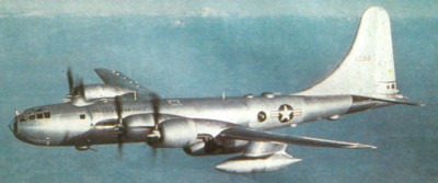
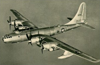
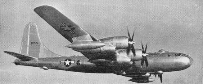
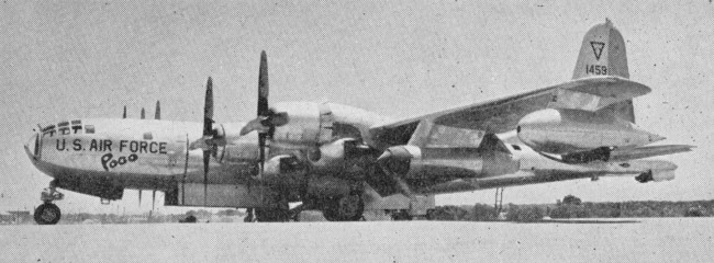
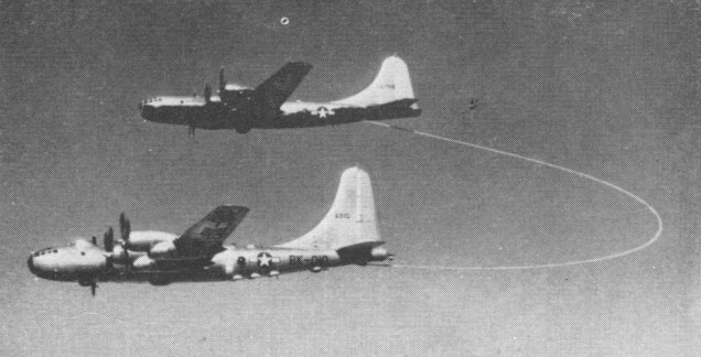
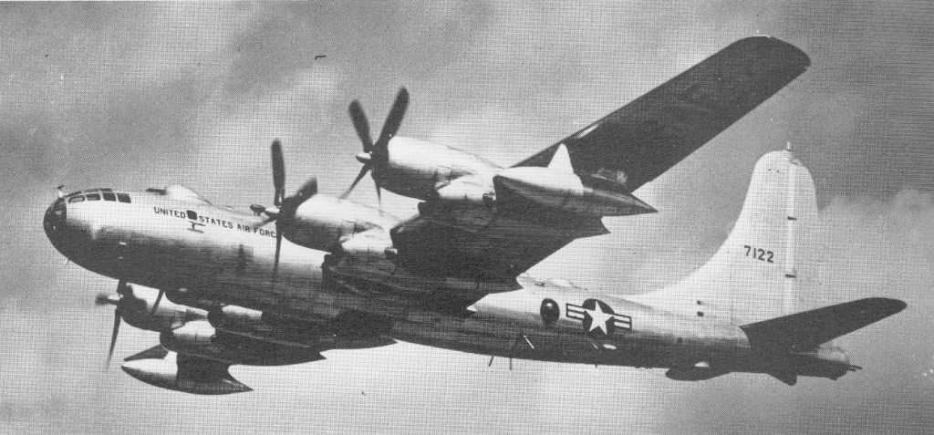
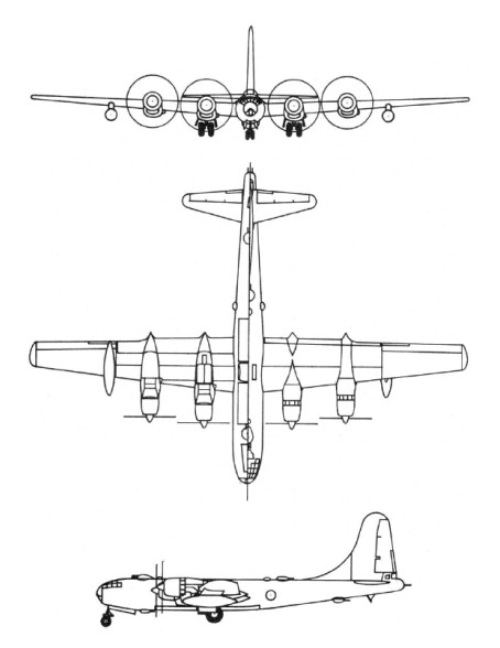
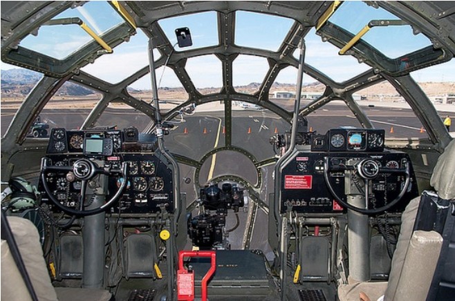
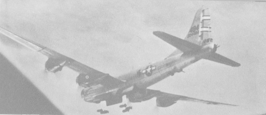
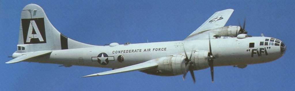
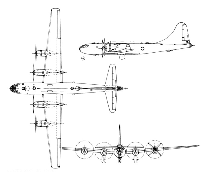
The B-50’s development was approved in 1944, when the aircraft was known as the B-29D. The Army Air Forces (AAF) wanted a significantly improved B-29 that could carry heavy loads of conventional weapons faster and farther. As World War II ended, the production of thousands of B-29s was cancelled. The B-29D survived, redesignated B-50 in December 1945, the improved bomber was now for the atomic role. The decision was pending availability of the intercontinental B-36 or of another bomber suitable for the delivery of atomic weaponry.
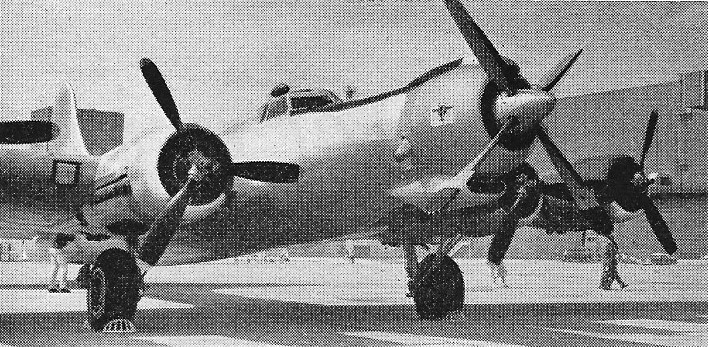
First flying on 25 June 1947 and looking identical to the B-29 Superfortress, the B-50 retained just 25 percent of the B-29’s original components. Changes distinguishing the B-50 from its predecessor included an all new aluminum wing design that made the aircraft more resilient and efficient. Vertical tail surfaces were now designed to fold down, allowing the massive bomber the capability to be housed in air force hangars.
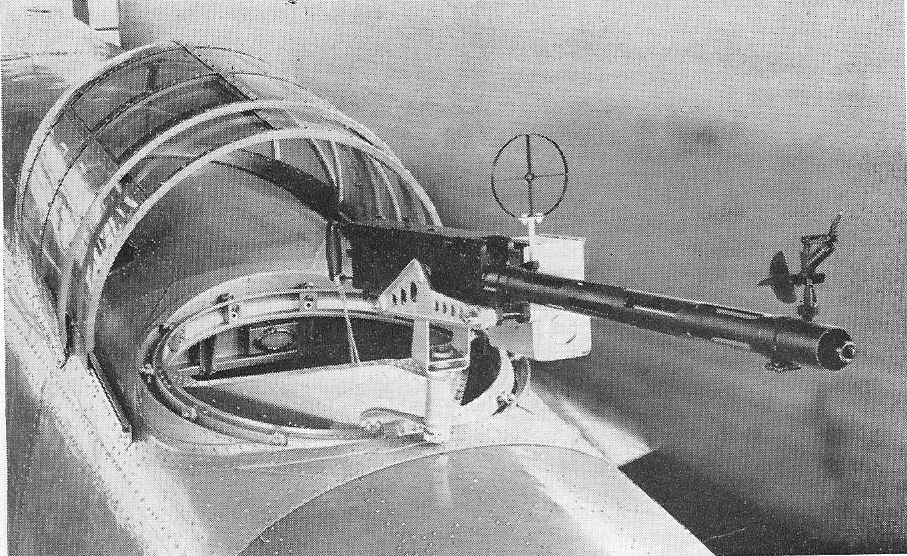
A four-engine heavy bomber powered by the Pratt & Whitney 3,500 horsepower R-4360-35 Wasp Major radial engine produced in about 750 examples from November 1949 up until February 1953. Accommodations for crewmen included a total of ten personnel with access to 12 x .50 caliber machine guns in remotely-controlled barbettes and a 20mm cannon. Up to 20,000lbs of internal ordnance could be carried.
Initial production models were the B-50A and B-50B.
Photo-reconnaissance versions included the RB-50E, F and G, and the TB-50D and TB-50H were navigation trainers.
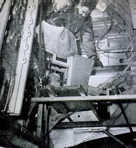
While the short-range B-50 was immediately recognized as a stopgap measure, the magnitude of the aircraft’s development problems proved unexpected. The B-50’s first difficulties stemmed from its bomb bay which, like that of the B-29, was too small to house the new bomb and its required components. The fast development of special weapons created more complications, since the individual components of every single type of bomb had to be relocated within the bomb bay’s narrow confines.
The B-50 soon exhibited engine malfunctions. Then, cracking of the metal skin on the trailing edge of the wings and flaps dictated extensive modifications. While these problems were being resolved, new requirements were levied on the aircraft. In 1949, as the proposed RB-36 remained a long way off, and because of the older RB-29’s deficiencies in speed, range, and altitude, some B-50s had to be fitted for the reconnaissance role. Fuel tank overflows, leaking fuel check valves, failures of the engine turbo-chargers, generator defects, and the like continued to plague every B-50 version.
Contrary to plans, most B-50s came off the production lines without the receiver end of the new air-to-air refueling system being developed by Boeing. Additional, and successful, modifications ensued. Nevertheless, the Strategic Air Command (SAC) had no illusions. The B-50, along with the B-36 (first delivered in June 1948), would be obsolete in 1951. That the B-50 did not start leaving the SAC inventory before 1953 was due to the production problems and many modifications of its replacement: the subsonic B-47.
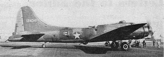
Boeing B-50D
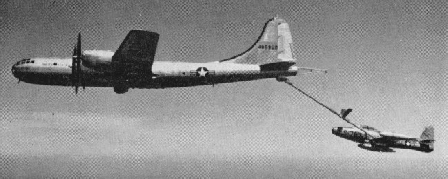
B-50’s would eventually be replaced by the jet-powered B-47 Stratojet by 1954, though many would go on to be modified as TB-50H crew and pilot trainers, the KB-50 aerial refueling aircraft and the RB-50 photographic reconnaissance platform.
Boeing KB-50K
The KB-50 refuelling tankers had two J47 turbojets added in underwing pods, and were redesignated KB-50K.
B-50 ‘Luckey Lady II’ encircled the world non-stop in 1949, refuelled four times
RB-50 ELINT
Still operational in 1955, the B-50D usually carries two 700-gal. fuel tanks or 4,000 lb. bombs under outer wings. All B-50’s would be retired from service by 1965.
B-50A Engines: 4 x Pratt & Whitney R-4360-35 Wasp Major, 2610kW Take-off weight: 76389 kg / 168410 lb Empty weight: 36764 kg / 81051 lb Wingspan: 43.05 m / 141 ft 3 in Length: 30.18 m / 99 ft 0 in Height: 9.96 m / 32 ft 8 in Wing area: 161.55 sq.m / 1738.91 sq ft Max. speed: 620 km/h / 385 mph Cruise speed: 378 km/h / 235 mph Ceiling: 11280 m / 37000 ft Range: 7483 km / 4650 miles Armament: 12 x 12.7mm machine-guns, 1 x 20mm cannon, 9000kg of bombs Crew: 11
B-50D Engines: 4 x Pratt & Whitney R-4360-35 Wasp Major, 3500hp Wingspan: 141 ft. 3 in (43.10m) Wing area: 1768 sq.ft Length: 100.00ft (30.48m) Height: 34.58ft (10.54m) Empty Weight: 80,601lbs (36,560kg) Maximum Take-Off Weight: 173,001lbs (78,472kg) Maximum Speed: 380mph (611kmh; 330kts) Cruise speed: 330 mph Maximum Range: 4,896 miles (7,880km) Service Ceiling: 36,713ft (11,190m) Armament: 12 x 12.7mm machine guns, 1 x 20mm cannon Internal bombload: 20,000lb Accommodation: 10
In March 1936, a team lead by Lysle Wood began work on an updated XB-15, the Model 316. This plane featured the all-glass nose that would make the B-29 distinctive. Designated the Y1B-20, it was 17 percent heavier than the eventual B-29. The Army was not interested. Boeing continued heavy bomber development in 1938 and 1939 with Models 330, 333, 333A, 333B, 334, and 334A. In August 1939 they began work on the Model 341, featuring a much improved wing: the Boeing Model 115 airfoil. Around 1938, General Henry H. ‘Hap’ Arnold, the head of the Army Air Corps, was growing alarmed at the possibility of war in Europe and in the Pacific. To prepare the Air Corps, Arnold created a special committee chaired by Brigadier General W. G. Kilner; one of its members was Charles Lindbergh. After a tour of Luftwaffe bases, Lindbergh became convinced that Nazi Germany was far ahead of other European nations. In a 1939 report, the committee made a number of recommendations, including development of new long-range heavy bombers. When war broke out in Europe, Arnold requested design studies from several companies on a Very Long-Range bomber capable of travelling 5,000 miles (8,000 km). Part of Arnold’s motivation for these studies was the fear that Britain might fall to the Nazis. In that event, it would be imperative that the Army Air Force have a bomber capable of flying round-trip from the U.S. East Coast to Europe to strike targets on the European mainland. Approval was granted on December 2. This request, R-40B, fitted perfectly with the research Boeing was doing at the time. On 29 January 1940, the Air Corps issued a request for proposals for a much larger bomber, which was to have the range for operation over the Pacific; this bomber would serve in the inevitable war with Japan. Four firms submitted design studies: the Boeing XB-29, Lockheed XB-30, Douglas XB-31, and Consolidated XB-32. Douglas and Lockheed soon withdrew, in part because Boeing was well ahead of them in the design process. On 6 September 1940 contracts were awarded to Boeing and Consolidated (later Convair) for the construction and development of two (later three) prototypes of their respective designs. Convair’s XB-32 Dominator was the first to fly, on 7 September 1942, but extensive development delayed its entry into service.
In early 1940, the Army Air Corps analysed the performance of bombers used in Europe against the Luftwaffe, and requested that the B-29 have self-sealing fuel tanks, more machine guns, and higher-caliber guns. Boeing incorporated these into a redesign of the Model 341, and resubmitted it to the Army Air Corps as Model 345, which would become the XB-29. Impressed by the mock-up completed in the spring 1941, the Army Air Corps had placed a massive order for 1,500 B-29s, a year before the prototype would fly for the first time on September 21, 1942. A long-range bomber was urgently needed, so service testing proceeded largely in tandem with production. The first B-29 rolled off the assembly line two months after the first service test flight. In under a year, the B-29 was in full-scale production. The USAAC’s specification had called for a speed of 644km/h, so the XB-29 had a high aspect ratio cantilever monoplane wing mid-set on the circular-section fuselage. Because such a wing would entail a high landing speed, the wide-span trailing-edge flaps were of the Fowler type which effectively increased wing area by almost 20%, thus allowing a landing to be made at lower speed. Electrically retractable tricycle landing gear was provided and, as originally proposed by Boeing, pressurised accommodation was included for the flight crew. In addition, a second pressurised compartment just aft of the wing gave accommodation to crew members who, in the third XB-29 and production aircraft, sighted defensive gun turrets from adjacent blister windows. The crew and aft compartments were connected by a crawl-tunnel which passed over the fore and aft bomb bays. The tail gunner was accommodated in a third pressurised compartment, but this was isolated from the other crew positions. Rather than the traditional bulky manned gun turrets, Boeing used small, remote-control units ‘networked’ together with an analog computer that compensated for factors such as air temperature and bullet drop. This system was very difficult to develop, but it proved effective. Each gun was served by a 1,000 round bullet belt.
The powerplant consisted of four Wright R-3350 Cyclone twin-row radial engines, each with two General Electric turbochargers mounted one in each side of the engine nacelle.
Prototype production was followed by 14 YB-29 service test aircraft, the first of these flying on 26 June 1943. Deliveries of YB-29s began almost immediately to the 58th Very Heavy Bombardment Wing (VHBW), a unit which had been established on 1 June in advance of the first flight. B-29 production was the most diverse aircraft manufacturing project undertaken in the USA during World War II, with literally thousands of sub-contractors supplying components or assemblies to the four main production plants: Boeing at Renton and Wichita; Bell at Marietta, Georgia; and Martin at Omaha, Nebraska.
Because of its highly advanced design, challenging requirements, and immense pressure for production, development was deeply troubled. The first prototype crashed during testing, killing the entire crew and several ground personnel. Changes to the production craft came so often and so fast that in early 1944, B-29s would leave the production lines and fly directly to modification depots for extensive rebuilds to incorporate the latest changes. This ‘battle of Kansas’ nearly sank the program, which was only saved by General Hap Arnold’s direct intervention. It would still be nearly a year before the aircraft was operated with any sort of reliability.
The most common cause of maintenance headaches and catastrophic failures, even more so than the advanced gunnery system, was the engine. Though the Wright R-3350 would later become a trustworthy workhorse in large piston-engined aircraft, early models were beset with dangerous reliability problems. It had an impressive power-to-weight ratio, but this came at a heavy cost to durability. Worse, the cowling Boeing designed for the engine was too close (out of a desire for improved aerodynamics), and the early cowl flaps caused problematic flutter and vibration when open in most of the flight envelope.
These weaknesses combined to make an engine that would overheat regularly when carrying combat loads; it frequently swallowed its own valves. The resulting engine fires were exacerbated by a crankcase designed mostly of magnesium alloy. The heat was often so intense the main spar burned through in seconds, resulting in catastrophic failure of the wing. This problem would not be fully cured until the aircraft was re-engined with the more powerful Pratt & Whitney R-4360 ‘Wasp Major’ in the B-29D/B-50 program, which arrived too late for World War II. Pilots, including the present-day pilots of the Commemorative Air Force’s Fifi, describe flight after takeoff as being an urgent struggle for airspeed. Radial engines need that airflow to keep cool, and failure to get up to speed as soon as possible could result in an engine failure and risk of fire.
The initial plan was to use B-29s to attack Japan from airfields in southern China, with the main base in India, and to attack other targets in the region from China and India as needed. This was an extremely costly scheme, as there was no overland connection available between India and China, and all the supplies had to be flown over the Himalayas. The first B-29s started to arrive in India in early April, 1944. The first B-29 flight to airfields in China (over the Himalayas, or “The Hump”) took place on 24 April 1944. The first B-29 combat mission was flown on 5 June 1944, with 77 out of 98 planes launched from India bombing the railroad shops in Bangkok (5 B-29s were lost to non-battle causes).
B-29 bomb aimer
On June 15, 1944, 47 B-29s launched from Chengtu in China bombed the Imperial Iron and Steel Works at Yawata, Japan. This was the first attack on Japanese islands since the Doolittle raid in April, 1942. The first B-29 combat loss occurred during this raid, with 1 B-29 destroyed on the ground by Japanese fighters after an emergency landing. Because of the extreme cost of operations, the raids against Japan from Chinese airfields continued at relatively low intensity. Japan was bombed on: 7 July 1944 (14 B-29s), 29 July (70+), 10 August (24), 20 August (61), 8 September (90), 26 September (83), 25 October (59), 12 November (29), 21 November (61), 19 December (36) and for the last time on 6 January 1945 (49). B-29s were withdrawn from airfields in China by the end of January, 1945. Throughout this period B-29 raids were also launched from China and India against many other targets throughout South-East Asia. However, the entire B-29 effort was gradually shifted to the new bases in the Marianas, with the last B-29 combat mission from India flown on March 29, 1945.
The need to use inconvenient bases in China for attacks against Japan ceased after the capture of the Marianas islands in 1944. On the islands of Tinian, Saipan and Guam a series of airfields were built, which became the main bases for the large B-29 raids against Japan in the final year of the war. The islands could be easily supplied by ship. The first B-29 arrived on Saipan on 12 October 1944, and the first combat mission was launched from there on 28 October 1944, with 14 B-29s attacking the Truk atoll. The first mission against Japan from bases in the Marianas was flown on 24 November 1944, with 111 B-29s sent to attack Tokyo. From that point ever more intense raids were launched regularly until the end of the war. These attacks succeeded in devastating all large Japanese cities and gravely damaged Japan’s war industries.
Perhaps the most recognized B-29 is the Enola Gay, which dropped the atomic bomb ‘Little Boy’ on Hiroshima on 1945 August 6. The Bockscar, also a B-29, dropped ‘Fat Man’ on Nagasaki three days later.
On Sunday 2 April 1944, the first B-29 Superfortress landed in Calcutta, India. It belonged to 58 Wing, 20th Bomber Command of the USAAF and had flown almost around the world, from the Boeing aircraft plant Wichita, Kansas to England, and then onto North Africa and the Orient. The plan was for B-29s to begin the strategic war against Japan.
On 16 June 1944 the US War Department announced the first wings of new US B-29 Superfortress bombers had taken off from bases in India, Burma and China, and have flown a massive raid on an “important target in Japan” from an altitude of 20,000 ft.
The B-29 was used in World War II only in the Pacific Theatre. It was later used in the Korean War, over the course of which they flew 20,000 sorties and dropped 200,000 tons (180,000 tonnes) of bombs. 3970 of the aircraft were built before they were retired in 1960. The B-29 was soon made obsolete by the development of the jet engine. With the arrival of the mammoth B-36, the B-29 suffered its first ignominy by being classified a medium bomber with the new Air Force. However, the later B-29D/B-50 variant was good enough to handle auxiliary roles such as air-sea rescue, electronic intelligence gathering, and even air-to-air refuelling. It was replaced in its primary role during the early 1950s by the Boeing B-47 Stratojet, which in turn was replaced by the Boeing B-52 Stratofortress. The final active duty variants were phased out in the mid 1960s. B-29 production totalled 1,644 from Boeing’s Wichita plant, with 668 built by Bell and 536 by Martin. The Renton plant produced only the B-29A variant, with a 12in wider span, later marks of the 2,200hp Wright R 3350 engines, changes in fuel capacity, and the addition of a four gun forward dorsal turret and armament: production continued until May 1946 and totalled 1,122 aircraft. The designation B-29B related to 311 of the aircraft built by Bell. These were reduced in weight by removal of all defensive armament except for the tail guns, which were then unmanned, being aimed and fired automatically by an AN/APG-15B radar fire-control system. The production total of 3970 B-29s of all versions saw a wide variety of employment in the post-war years, operating under several designations. A number of B-29s were used operationally during the Korean War.
B 29s were followed by several hundred of many versions of the B 50, with more powerful engines and other changes. These saw action only as tankers in the Vietnam War, but B 29s operated throughout the Korean War, the 22nd and 92nd Bomb Groups opening strategic missions as early as 13 July 1950. Though never more than 99 B 29s were on strength, the two groups flew 21,000 sorties and dropped 167,100 tons, more than the tonnage dropped by B 29s in World War II.
The US Operations Crossroads, with a budget of $1.3 billion, was to determine atomic bomb effectiveness using three tests. The first, Able, was air dropped, Baker detonated under water. Charlie, the third was later cancelled. For the first test site the Navy chose Bikini atoll. On 1 July 1946, the Able bomb was loaded into a B-29 Superfortress named ‘Dave’s Dream’. Just before 9am the bomb was released, exploding 518 ft above Bikini lagoon. The 23 kiloton test was a success, generating a 100,000 degree Fahrenheit fireball with the mushroom cloud reaching 40,000 ft.
B 29s force landed in Soviet territory were dissected in minute detail, and the Tupolev design bureau built first a simple transport, the Tu 70, followed in July 1947 by the first Tu 4 bomber. This was a B 29 except in having 23 mm cannon in its five twin turrets. About 400 were built, but they did not see action; their main importance was that they were the starting point for all today’s Tupolev strategic turboprop and jet bombers. Some of these remained in service into the 1960s in the Soviet Union. All but one of the Tu-4s were scrapped in the 1960s. The lone example of a Tu-4 known to exist today is located at the Yuri Gagarin Air Force Academy near Moscow, as a static display. This particular airplane was tasked with bombing the Budapest headquarters of the Hungarian rebel movement during the 1956 rebellion; but although the mission was rehearsed it was never put into play.
The last RB-29 was shot down by two MiG-15s above the east coast of Hokkaido, Japan, on 4 September 1954. The aircraft allegedly flew over Soviet territory on the Pacific coast, according to the Soviet. Ten or eleven of the crew survived.
The KB-29 was the tanker version of the B-29, the SB-29 the search & rescue version, carrying a lifeboat; the DB-29 was a drone controller, the TB-29 a trainer, the RB-29 a reconnaissance aircraft. Some B-29s were also used as launch aircraft for research aircraft like the X-1 and X-2.
Boeing eventually converted about 100 to KB-29 tankers.
The KB-29P flying boom flight refuelling tanker version and the SB-29 search and rescue aircraft were still in service in 1955. The SB-29 equipped to carry an A.3 remote control lifeboat under its fuselage.
Boeing KB-29P
Eventually 4221 B-29 were built.
Events:
1 June 1943 The USAAF’s 58th Heavy Bombardment Wing was established. This wing was equipped with Boeing B-29 superfortresses for strategic attack on Japan.
15 June 1944 47 B-29s bombed the imperial iron and steel works at Yawata Japan.
20 November 1945 A new non-stop distance record of 7,916 miles was set by B-29 bomber “Pacusan Dreamboat” after flying from the island of Guam to Washington DC.
1 November 1954 The last B-29 in front-line service, based at Kadena, was retired. The B-29s were replaced by the B-47.
B-29 Engines: Four Wright R-3350-21 or -23 “Cyclone” radials each equipped with two type B-11 turbo superchargers; later B-29 models fitted with -23A, -41 or -57 Cyclone radials Engine gear ratio: 20:7 (.35) Take-off power: 2,200 hp at 2,600 rpm w/ manifold pressure of 47.5 in. Military power: 2,200 hp at 2,600 rpm w/ manifold pressure of 47.5 in at 25,000 ft. Normal rated power: 2,000 hp at 2,400 rpm at sea level Idling speed: 600 +/- 50 rpm (propeller at increase rpm) Propellers: Manufacturer: Hamilton Standard Propeller division of United Aircraft Corp. Type: 4-blade, full feathering Diameter: 16 ft. 7 in. Span: 141 ft. 2.76 in. Length: 99 ft. 0 in. Height: 27 ft. 9 in. (at rest) 27 ft. 6.7 in. (taxi position) Maximum fuselage diameter: 9 ft. 6 in. Height to centerline of propeller hub (taxi position) Inboard engines: 9 ft. 5.6 in. Outboard engines: 10 ft. 8 in. Ground clearance of inboard propeller tips (taxi position): 14.1 in. Airfoil section: Boeing 117 Root: 22% Tip: 7% Chord root: 17 ft. Chord tip (70 feet 10 inches from centerline of fuselage): 7 ft. 5 in. Incidence: 4 degrees Dihedral: 4 degrees 29 minutes 23 seconds Sweepback: 7 degrees 1 minute 26 seconds Stabiliser: Span: 43 ft. Maximum chord: 11 ft. 2.4 in. Areas: Wing (less ailerons): 1609.68 sq. ft. Wing (flaps extended, plus ailerons): 2070.88 sq. ft. Alierons (total, including tabs): 129.2 sq. ft. Flaps (total): 332 sq. ft. Stabilizer and elevators (including tabs): 333 sq. ft. Elevators (total including tabs): 115 sq. ft. Elevator trim tabs (total): 10.12 sq. ft. Vertical fin: 131.9 sq. ft. Dorsal fin: 40.6 sq. ft. Rudder (including tab): 65.5 sq. ft. Rudder trim tab: 5.79 sq. ft. Weight: 133,500 lbs. (maximum overload) 105,000 lbs. gross Armament: 10 or 12 .50-cal. machine guns and one 20mm cannon plus 20,000 lbs. of bombs. Fuel Tank Capacities: Regular wing (22 cells): 5608 US gals. (4669 Imp.) Auxiliary center wing (four cells): 1333 US gals. (1110 Imp.) Auxiliary bomb bay (four cells): 2560 US gals. (2133 Imp.) Net Total capacity: 9501 US gals. (7912 Imp.) Crew: Normal crew of 10 consists of Pilot, Co-Pilot, Flight Engineer, Bombardier, Navigator, Radio Operator, (2) Side Gunners, Top Gunner, and Tail Gunner Maximum speed: 357 mph at 25,000 ft. Cruising speed: 220 mph Range: 5,600 miles maximum ferry range and 3,250 miles with 20,000 lbs. of bombs Service ceiling: 33,600 ft.
B-29 Crew: 10 Engines: 4 x Wright R-3350-23-23A/-41 Cyclone 18, 1641kW Take-off weight: 56245 kg / 124000 lb Empty weight: 31815 kg / 70140 lb Wingspan: 43.05 m / 141 ft 3 in Length: 30.18 m / 99 ft 0 in Height: 9.02 m / 29 ft 7 in Wing area: 161.27 sq.m / 1735.89 sq ft Max. speed: 576 km/h / 358 mph Cruise speed: 370 km/h / 230 mph Ceiling: 9710 m / 31850 ft Range w/max.fuel: 5230 km / 3250 miles Range w/max.payload: 2880 km / 1790 miles Armament: 11 x 12.7mm machine-guns, 9000kg of bombs
B-29A Engines: 4 x Wrigth R-3350-23 (supercharged radial engines), 1600kW/ 2,200 hp Wing Span: 142.26ft (43.36m) Length: 99.02ft (30.18m) Height: 29.56ft (9.01m) Wing Area: 161.27 sq.m Empty Weight: 71,361lbs (32,369kg) Max.Weight: 141,102lbs (64,003kg) Maximum Speed: 358mph (576kmh; 311kts) Service Ceiling: 31,808ft (9,695m) Maximum Range: 4,100miles (6,598km) Rate-of-Climb: 526ft/min (160m/min) Wing loading: 337 kg/sq.m Armament: 1 x 20mm, 12 x mg 12.7mm, Bombload: 20,000lbs / 9072 kg Crew: 10 (pilot, co-pilot, flight engineer, bombardier, navigator, radio operator, side gunners (two), top gunner, and tail gunner)
B 29A Engines: 4 x four 2,200 hp (1641 kW) Wright R 3350 57 (or related) Duplex Cyclone 18 cylinder radials. Wing span: 43.05 m (141 ft 3 in). Length: 30.18 m (99 ft 0 in). Height: 9.02 m (29 ft 7 in). Wing area: 161.28 sq.m (1,736.0 sq ft). Weight empty: 31816 kg (70,140 lb). MTOW: 64002 kg (141,100 lb). Maximum speed: 576 km/h (358 mph) at high altitudes. Service ceiling: 9750 m (32,000 ft). Range with maximum bombload: 5230 km (3,250 miles). Armament: bombload of 9072 kg (20, 000 lb), plus 10 12.7 mm (0,5 in) machine guns and one 20 mm cannon in five turrets. Crew: 10.
B 29B Engines: 4 x four 2,200 hp (1641 kW) Wright R 3350 57 (or related) Duplex Cyclone 18 cylinder radials. Wing span: 43.05 m (141 ft 3 in). Length: 30.18 m (99 ft 0 in). Height: 9.02 m (29 ft 7 in). Wing area: 161.28 sq.m (1,736.0 sq ft). Maximum speed: 576 km/h (358 mph) at high altitudes. Service ceiling: 9750 m (32,000 ft). Range with maximum bombload: 5230 km (3,250 miles). Weight empty: 31816 kg (70,140 lb). MTOW: 64002 kg (141,100 lb). Armament: bombload of 9072 kg (20, 000 lb), plus 10 12.7 mm (0, 5 in) machine guns and one 20 mm cannon in five turrets. Crew: 10.
KB-29P Flight refuelling tanker. Engines: 4x 2,200 h.p. Wright R3350-57 or -83 Wingspan: 141 ft. 3 in Length: 99 ft. Max speed: 351 m.p.h. Ceiling: over 35,000 ft. Range: 4,600 miles
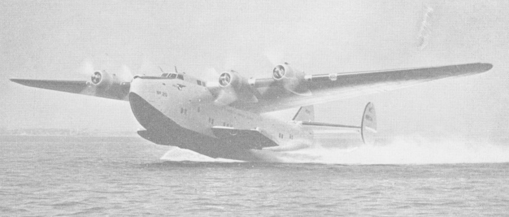
As early as January 1935, Pan American Airways had signified to the US Bureau of Air Commerce its wish to establish a transatlantic service and, the airline wanted a new aircraft for the route.
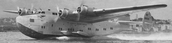
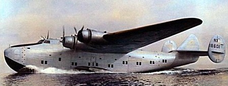
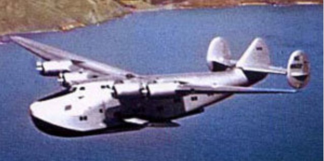
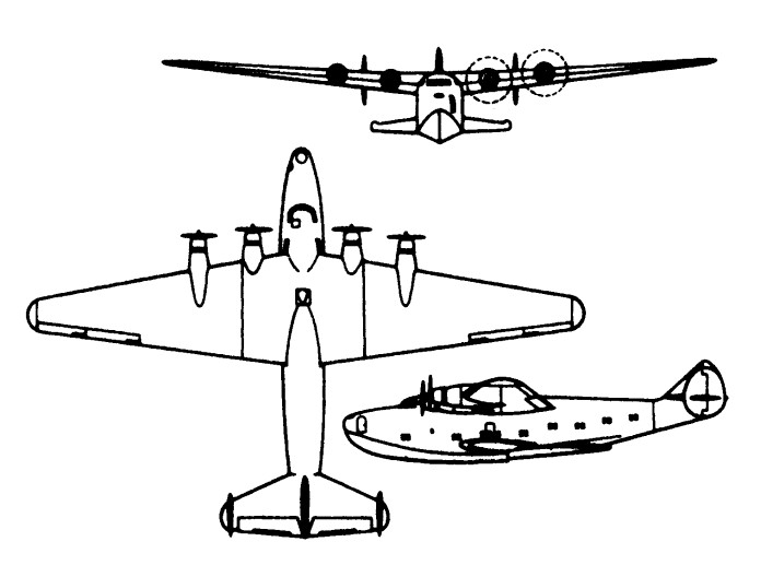
Boeing submitted a successful tender to the Pan American specification and a contract for six Boeing Model 314 flying-boats was signed on 21 July 1936. They used features of the XB-15 heavy bomber, adapting the wing and horizontal tail surfaces for its 37421kg gross weight flying-boat, which could accommodate a crew of 8 and up to 74 passengers in four separate cabins. The engines 1119kW Wright GR-2600 Double Cyclones which gave the machine a maximum speed of 311km/h. The fuel capacity of 15898 litres giving a maximum range of 5633km. Some of the fuel was stored in the stabilising sponsons, which also served as loading platforms. The first Boeing 314 made its maiden flight on 7 June 1939, this original version having a single fin and rudder, later replaced by twin tail surfaces to improve directional stability. These proved to be inadequate, and the original centreline fin was restored, without a movable rudder.
The aircraft was awarded Approved Type Certificate No. 704 and entered transatlantic airmail service on 20 May 1939. PAA Boeing 314 ‘Yankee Clipper’ flew by way of the Azores to Spain and then on to Southampton. On June 17 ‘Atlantic Clipper’ made first passenger crossing, carrying reporters and airline officials. Regular passenger service commenced on 28 June 1939, when ‘Dixie Clipper’ carried twenty-two paying passengers. One passenger having booked his seat in 1931. At that time the Model 314 was the largest production airliner in regular passenger service.
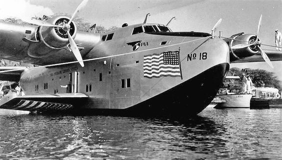
Known as “California Clippers” they operated over the South Pacific Ocean routes for Pan American Airlines. One such “California Clipper” flew from Los Angeles Harbor to Auckland, New Zealand, an 8,000-mile, 50-hour route with night layovers at Honolulu, Canton Island, and Noumea, New Caledonia. On two decks—an upper or control deck and a passenger deck—there were accommodations for a crew of 11 and 68 passengers or 36 sleeping passengers. The passenger deck was divided into nine sections, including a lounge, six separate passenger compartments, a specially furnished deluxe compartment, a galley and restrooms.
Clippers were in service with distinguishable names from 1939 through 1951 and were represented as the Honolulu Clipper, Cape Town Clipper, Anzac Clipper, Pacific Clipper, American Clipper, Yankee Clipper, California Clipper and the Atlantic Clipper – all operated by Pan Am.
Pan American ordered another six aircraft which were designated Model 314A, improved by the installation of 1193kW Double Cyclones with larger-diameter propellers, and additional 4542 litres of fuel capacity, and a revised interior. The first Model 314A flew on 20 March 1941 and delivery was complete by 20 January 1942. Five of the original order were retrospectively converted to Model 314A standard in 1942. Three of the repeat order were sold, before delivery, to BOAC for transatlantic service and operation on the Foynes-Lagos sector of the wartime ‘Horseshoe Route’. The three Boeing 314As, G AGBZ Bristol, G AGCA Berwick, and G AGCB Bangor, with fuel capacity of 5,448 US gallons giving a range of over 3,600 miles, were acquired by the British Government and delivered new from Boeing’s Seattle factory specifically to provide the UK West Africa ‘lifeline’. The three Boeings commenced operation UK West Africa in May 1941. It transpired that a valuable, albeit irregular, trans Atlantic service was an incidental development due to the necessity for them to return to their Baltimore base for certain overhauls after every 120 hours flying, and Atlantic flights were therefore interpolated into the schedules to permit this to happen. BOAC operated its last B.314A on January 17, 1948.
Of Pan American’s nine Model 314/ 314As, four were requisitioned by Army Transport Command and given the military designation C-98. They were little used, however, and in November 1942 one was returned to the airline. The other three were transferred to the US Navy to join two acquired direct from Pan American; the airline provided crews for the US Navy’s B-314 operations and the aircraft were partially camouflaged but operated with civil registrations.
BOAC and Pan American terminated Boeing Model 314 services in 1946 and the surviving aircraft were sold to American charter airlines
Boeing 314 Clipper Engines: 4 x Wright R-2600 Double Cyclone, 1,500 hp
Boeing 314A Clipper (C-98) Engines: 4 x Wright R-2600 Cyclone 14, 1193kW, 1600 hp Props: full-feathering constant-speed Length: 32.31 m / 106 ft 0 in Height: 8.41 m / 27 ft 7 in Wingspan: 46.33 m / 152 ft 0 in Wing area: 266.34 sq.m / 2866.86 sq ft Maximum Take-Off Weight: 83,776lbs (38,000kg) Empty Weight: 48,281lbs (21,900kg) Fuel capacity: 5408 USG Max. speed: 311 km/h / 193 mph Cruise speed: 295 km/h / 183 mph Maximum Range: 3,664miles (5,896km) Ceiling: 4085 m / 13400 ft Passengers: 74
In early 1934 Boeing began design studies for a multi-engine bomber and a basically similar civil transport. When, in June 1934, the USAAC invited proposals for a new bomber, Boeing’s Model 299 was revamped to meet the Army specification and duly became built by the thousands as the B-17 Flying Fortress.
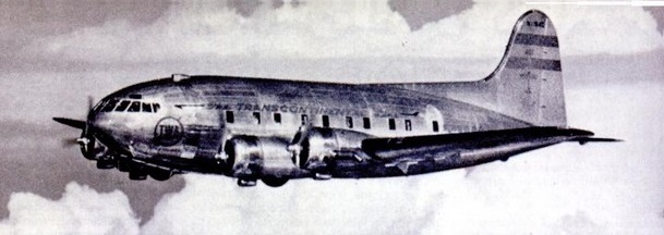
The Model 300 was also changed as ideas were developed and in its Model 307 form was similar to the B-17C, except for a very different fuselage. This was of circular cross-section with pressurisation for the crew of five and 33 passengers. The Model 307 introduced an extra crew member – known as the flight engineer – to relieve the captain of certain duties such as power plant, fuel and pressurisation management and monitoring.
The prototype Model 307 (named Stratoliner because of its high cruising ceiling) flew for the first time on 31 December 1938.
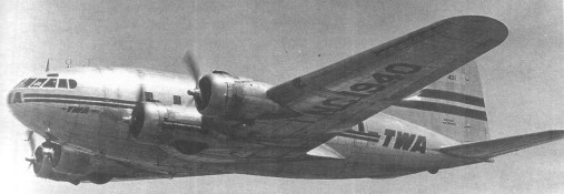
A total of ten were built: the prototype; five SA-307B for Transcontinental & Western Air; three S-307 for Pan American; and a single SB-307B for the late Howard Hughes.
First delivered to PanAm in 1940, the Boeing 307 went into service in 194, carrying passengers on long haul American routes. The night plane version had berths for 16 passengers and reclining chairs for a further 9.
The 307B differed from the 307 in having 1100 Wright Cyclone GR-1820-G105A engines instead of G-102s, and slotted flaps in place of split trailing edge flaps.
TWA’s SA-307B were impressed for service with the Army’s Air Transport Command during World War II, being used as C-75 for VIP transport over the North and South Atlantic.
307B
The TWA 307Bs were extensively modified after wartime USAF service; the cabin pressurisation equipment was removed, and B-17 wings and 1200 hp Wright R-1820 engines were fitted. These were eventually sold to France.
A special model SB-307B for Howard Hughes was built with more powerful engines and extra fuel tanks for an around-the-world flight that was cancelled due to the start of World War II. The flight was never made. It was the first Stratoliner delivered to a customer; its initial flight (with experimental license NX19904) occurred on July 13, 1939. Postwar it was fitted with a luxury interior, including a bedroom, and named The Flying Penthouse.
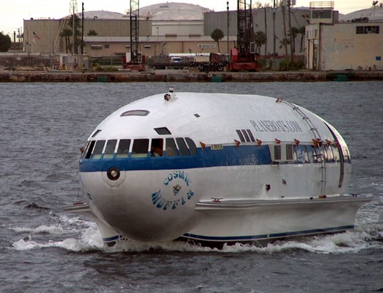
A 1964 hurricane severely damaged it and rendered it unflyable. In 1969 it was purchased as scrap for $61.99 — the fuselage was salvaged (the aft rounded pressure bulkhead formed the cabin after end), then mounted on a boat hull and converted into a luxury yacht named The Londonaire. It was rebuilt beginning in 1994, and is a Florida based, operating yacht named Cosmic Muffin, with N19904 painted on its sides.
S-307 Engines: 4 x Wright GR-1820 Cyclone, 671kW Take-off weight: 19050 kg / 41998 lb Empty weight: 13608 kg / 30001 lb Wingspan: 32.61 m / 106 ft 12 in Length: 22.66 m / 74 ft 4 in Height: 6.34 m / 20 ft 10 in Wing area: 138.05 sq.m / 1485.96 sq ft Max. speed: 396 km/h / 246 mph Cruise speed: 354 km/h / 220 mph Ceiling: 7985 m / 26200 ft Range 50 % pwr: 1,635 miles / 2,616 km Crew: 4 Pax cap: 33
The L-15 Scout was a light and small observation liaison aircraft produced in limited numbers by the Boeing Aircraft Company following World War 2 – only twelve of the type were produced with the United States Army becoming its top operator. The YL-15 requirements included an aircraft that could be quickly dismantled and loaded on a standard 2.5 ton truck.
First flight was achieved on July 13th in 1947 and production spanned from 1947 into 1949.
The all-metal construction L-15 was designed for operations from short runways (STOL) and specifically intended for the light scout observation role. The L-15 was designed at Boeing’s Wichita, Kansas facility.
The aircraft featured a high mounted monoplane wing assembly to which were affixed “flaperons”, wing devices that could double as ailerons and flaps. The two-person crew, made up of the pilot and the observer, sat in a glassed-in nacelle-type fuselage under the main span of the wings. The engine was mounted at the extreme front of the fuselage with the empennage extended out over the rear portion of the aircraft. The tail section had twin vertical tail fins. The undercarriage was a conventional “tail-dragger”, with two main landing gears and a tail wheel. All were fixed and the tail wheel was positioned under the rearward portion of the fuselage nacelle. The aircrafts size made it suitable for transport in a C-97 aircraft, that is once broken down for the journey. Should the mission call for it, the L-15 could also be fitted with twin floats for water landings.
The Scout could be towed as a glider at speeds up to 165 mph without having its airscrew removed.
No firm L-15 Scout contracts were secured. The remaining seven were later employed by the Federal Fish and Wildlife Service.
Boeing L-15 Scout Engines: 1 x Lycoming O-290-7, 125hp. Length: 25.00ft (7.62m) Wingspan: 39.99ft (12.19m) Height: 8.69ft (2.65m) Empty Weight: 1,512lbs (686kg) Maximum Take-Off Weight: 2,055lbs (932kg) Maximum Speed: 112mph (180kmh; 97kts) Rate-of-Climb: 628ft/min (191m/min) Service Ceiling: 16,398ft (4,998m) Accommodation: 2
Designed to a US requirement for a four-engine bomber capable of long distance travel with a full 2,000lb bombload and reach speeds between 200 and 250 miles per hour. The result was the Boeing Model 229 which first flew in 1934, though was later lost to pilot error. Nevertheless, the US Army Air Corps pursued the design with an order for further developmental models fitted with differing powerplants. Early B-17 models were mostly developmental production variants that included the additions of seal-sealing fuel tanks, better armor protection and a redesigned tail.
America’s USAAC had been a little ahead of Britain in specifying their need for a four engined bomber, and the prototype Boeing Model 299 / XB 17 designed to meet this requirement flew for the first time on 28 July 1935. Powered by four 750 hp Pratt & Whitney Hornet engines, the prototype crashed three months later at Wright Field when the control locks were inadvertently left engaged before takeoff.
A pre production batch of 13 Y1B 17s was bought for evaluation.
It was not until 1938 that the USAAC was able to place an order for 39 production B-17B, the last of this batch entering service in March 1940. These were the first B-17 production aircraft to be equipped with turbocharged Wright Cyclone engines, providing a higher maximum speed and much increased service ceiling.
Of the B-17C which followed, a batch of 20 were supplied to the RAF (designated Fortress I) and used operationally in Europe for evaluation, leading to improved B-17D and B-17E aircraft with self-sealing fuel tanks and revised armour and armament.
The Royal Air Force used them to bomb the German naval base at Wilhelmshaven on July 8th, 1941, marking the B 17’s first hostile action.
In late Summer of 1941, Great Britain bought 20 of the B-17C bombers recently produced by the USA, but the RAF had nothing but bad experiences with them. The B-17C’s first war deployment was on Monday 8 September 1941, when they attacked several targets along the Norwegian coast from from close to 20,000ft / 9000m. But the Germans received radar warning of their presence and sent out Me 109s from 77 Sqn, 13th Fighter Wing (based on Stavanger), which shot down 2 Fortress Is and seriously damaged three. After other fiascos with the B-17C, British Bomber Command concluded that they were completely unsafe, ineffective and unsuitable for use in any serious missions.
Following an extensive redesign, to increase armour and armament, new versions were introduced and were widely used by the Americans, both in Europe and the Pacific.
Y1B-17
The initial definitive Flying Fortress model would arrive with 512 examples of the B-17E model which were the first to incorporated the twin .50 caliber tail armament for defense.
Many changes were made as a result of combat experience first by the RAF and then by the USAAF in Europe. Even the B 17E , armed with one 7.62mm and 12 12.7mm machine-guns for defence and able to carry a maximum 7,983kg of bombs, was given a mauling by the Luftwaffe when it first ventured over Europe in daylight: but the Americans stood by their beliefs in the effectiveness of day bombing added still more guns, learned new tactics and eventually made possible the crushing round the clock bomber offensive. This model was followed by the similar B-17F models of which 3,405 were produced.
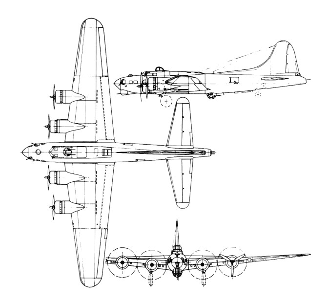
A further modification programme, this time to improve the bomber’s ability to repel air attacks from the front, produced the B17G with its twin-gun ‘chin’ turret which you can see clearly on this example.
Most extensively built variant was the B-17G (8,680), built by Douglas (2,395) and Lockheed Vega (2,250) as well as at the Boeing plant, Seattle (4,035). The B 17G model, the seventh variation of the original design, was equipped Pratt & Whitney R-1820-97 radial engines with super-chargers that allowed the airplane to cruise at 35,000 feet at a maximum speed of 285 miles per hour. It also carried up to thirteen .50 caliber machine guns and 6,000 pounds of bombs. The addition of a chin turret below the nose (containing two 12.7mm machine-guns) provided better defence against the head-on attacks. U.S.forces used it primarily for high level daylight bombing over Europe. The formidable machine gun placement enabled B 17s to develop a highly effective defensive tactical formation. Production of the B-17G started in July 1943.
B-17G manufactured after January 1944 were no longer given a camouflage coating because they were lighter and faster without it
The bombardier sat on a type of swiveling stool with a Norden Bombsight before him. The navigator sat off-set to his rear at a small map-filled desk. Both were supplied with defensive .50 caliber machine guns with the Bendix chin turret under the bombardiers control in the G model and onwards. Access to the nose was accomplished through a smallish passage way underneath the main flight deck.
The pilot and co-pilot sat on the flight deck above and behind the navigator’s position with the pilot to the left and his copilot to the right with both offered equal control access and views of all four of the engines. To their rear was the top gunners position with a catwalk crossing between the payload in the bomb bay. Once past the bomb bay, the radio operators station and his equipment was apparent. The radio operator was also afforded a table and seating along with his communications equipment. Access to the belly turret was available following this area, which further opened up to the staggered waist gunner positions which might or might not have been covered by plexiglass depending on the model.
On 1 July 1942 the first heavy bomber of the American 8th Army Air Force laned in Britain by the North Atlantic route. B-17E “Jarring Jenny” landed at Prestwick airfield, Scotland,
The B-17 flew the 8th Air Force’s first combat mission out of England in August 1942. At 3:20pm on Monday 17 August 1942, 12 B-17E of the 97th Bomber Group (US 8th Air Force) took off on their first mission over Europe, flying with four RAF Spitfire squadrons to provide them cover. US Brigadier General Ira Eaker flew with them, in the plane of the Group Commander, known as ‘Yankee Doodle’. The bombers target was Sotteville-les-Rouen on the left bank of the Seine, site of a railway switch yard crucial to the supplying of Le Harve. The Flying Fortresses released their 166 ton bombload from an altitude of over 22,000 ft. all the bombers returned to base.
The British were skeptical about daylight bombing, but the American strategy was made possible by the ruggedness built into high-flying bombers like the B-17 and by the deadly accuracy of the Norden bombsight. Used as the spearhead of the U.S. Army Air Force’s attacks in Europe, the aircraft also saw combat duty in all theaters of war. Three days after Pearl Harbor, the Japanese convoys en route to Luzon in the Philippines were met by Flying Fortresses.
They flew high in huge formations, protecting each other with cross fire, and dropped 640,036 tons of bombs in Europe for a loss of 4,750 aircraft.
Special variants included the B-40 with up to 30 machine-guns/cannons, which was intended as a B-17 escort, but proved to be an operational failure; BQ-7 pilotless aircraft packed with explosives to be deployed against German targets by radio control, which failed due to unreliable control equipment; CB-17 and C-108 transports; and F-9 long-range B-17 equipped to serve as an air-sea rescue aircraft and able to deploy a lifeboat carried beneath the fuselage.
The YB-40 escort fighter variant airframe and engines were typical B-17 but the armament was 31 guns. The largest was a 40mm faired into the radio hatch. In each waist position was a 20mm cannon plus two 0.5in machine guns. A four-gun turret was in the nose and another in the tail. The upper turret had four more 0.5in, the ball turret two. There were 10 more 0.5in machine guns in various locations.
At the height of production Boeing’s Seattle plant alone produced a completed aircraft every ninety minutes. A total of 12,731 built by Boeing, Douglas, and Lockheed Vega of which just over two-hundred were supplied to the RAF.
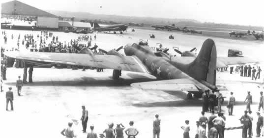
B-17 “Memphis Belle” would be stored at Altus AAF after public relations tour
RAF forces took several B-17 models with their applied “Fortress 1”, “Fortress 2” and “Fortress 3” designations, utilizing some in the electronic countermeasures role. Reconnaissance variants appeared with the US Army Air Corps, US Navy and US Coast Guard as well, each with differing designations shown below.
The B-17 Flying Fortress accounted for over 290,000 sorties with 640,000 tons of ordnance dropped during World War Two.
The German 200th Bomber Wing, KG200, carried out special transport missions using captured US B-24 Liberator and B-17 Flying Fortress which the Germans called by the code name Dornier Do 200.
Versions of the wartime Flying Fortress were still in service in 1955 include lhe U.S.A.F.’s QB-17G drone, SB-17 with an airborne lifeboat and CB-17G V.I.P. transport; and the U.S. Navy’s PB-1G air-sea rescue and PB-1W radar early-warning aircraft. All have four Wright R-1820-97 piston engines.
Boeing QB-17G Fortress
QB-17 testing guided missiles
US Navy and Coast Guard rescue version are similar to the SB-17G is designated PB-1G.
SB-17G
In New Mexico in 1950, Project Cirrus involved seeding rain clouds with dry ice from a B-17.
Project Cirrus
Project Cirrus
Project Cirrus
USAF Research & Development Command B-17G testbed with 3500hp Wright R-3350
XB-17 Engines: 4 x P&W Hornet, 750 hp Wingspan: 103 ft 9 in Length: 68 ft 9 in Take-off weight: 43,000 lb Bombload: 2570 lb Loaded range: 2000 mi at 204 mph
STANDARD DATA: Gross weight: 49,650 lb Empty weight: 30,620 lb Fuel capacity: 1,700 Usgals Engines: four 1,200 hp Wright Cyclone radials. Top speed: 323 mph Cruise speed: 250 mph Climb to 25,000 ft.: 41 min Range: 3,400 nm Ceiling: 37,000 ft.
B-17 Engines: 4 x Wright R 1820-97, 1,200 hp, 885kW Length 73.9 ft. (22.5 m) Height: 5.8 m / 19 ft 0 in Wing span: 103 ft 8 in (31.6 m) Wing area: 141.9 sq.m / 1527.40 sq ft Weight empty 32,250 lb. (14,630 kg) Max. bomb load: 9,600 lb (4,350 kg) Max. Speed 317 mph (510 kph) Cruise speed: 250 km/h / 155 mph Range 2,000 miles (3,220 km) with 4,000 lb. of bombs Ceiling: 10700 m / 35100 ft Crew: 10 Armament: Up to thirteen 0.30 and 0.50 in. machine guns
B-17E Engine: 4 x Wright R-1850-65 Cyclone, 1200 hp Wing span: 103 ft 9 in (31.62 m) Length: 73 ft 10 in (22.5 m) Height: 19 ft 2 in (5.84 m) Engines: 4 x Wright, 1200 hp Max TO wt: 53,000 lb (24,040 kg) Max level speed: 275 kts / 317 mph / 510 kph Service ceiling: 36581 ft / 11150 m Range: 2592 nm / 4800 km Crew: 9 Armament: 13x MG 12,7mm, 7985 kg Bomb
B 17G Engines: 4 x Wright Cyclone R-1820-97, 1,200 hp Wing span: 103 ft. 9.5 in / 31.62m Length: 74 ft. 9 in / 22.78m Height: 19 ft. 1 in / 5.82m Wing area: 1,420.0 sq ft / 131.92 sq.m Loaded weight: 66,000 lb Empty Weight: 36,136lbs (16,391kg) Maximum Take-Off Weight: 72,003lbs (32,660kg) Maximum Speed: 287mph / 462kmh; 249kts at 25,000 ft / 7,620 m Cruise speed: 182 mph Rate-of-Climb: 541ft/min (165m/min) Climb to 20,000 ft / 6,095 m: 37 min 0 sec Service Ceiling: 35,597ft (10,850m) Armament: 13 x 0.5in Browning mg Bombload: 8000 lb / 17,600 lb Crew: 10 Range: 3,400 miles / 5,470 km Range with 500lb load: 2100 miles / 3,220km
CB-17G
QB-17G Fortress Engines: four Wright R-1820-97 Span: 103 ft. 9 in Weight: 49,500 lb Max Speed: 295 m.p.h.
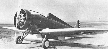
The P-29 or company Model 264 was a Boeing effort to improve on the P-26 ‘Peashooter’. It dispensed with the drag-inducing fixed gear, struts and bracing wires. A low-set cantilever wing monoplane pursuit ship with retractable landing gear, one of the three machines built attained a speed of 376km/h at 2286m with its 410kW Pratt & Whitney R-1340-35 engine. Initially flown on 20 January 1934, the first of the three airframes was originally designated XP-940 and was built with an enclosed, flush canopy. Boeing pilot Billy Acker asserted that the canopy ‘rattled like a bird cage’. After brief flight tests in which Army pilots also judged the canopy impracticable, this first airframe was returned to the manufacturer, rebuilt with the more traditional open cockpit, and redesignated YP-29A The second airframe, designated YP-29, added landing flaps to the basic design while the third, the YP-29B, added greater dihedral to the wings. But flight tests confirmed that the P-29, which was heavier than the P-26, offered at best only a very marginal improvement in performance. Though the three airframes were exhaustively tested well into the mid-1930s and contributed to institutional knowledge about fighter design, they were eventually deleted from inventory and scrapped.
Engine: 410kW Pratt & Whitney R-1340-35 Take-off weight: 1620 kg / 3572 lb Empty weight: 1167 kg / 2573 lb Wingspan: 8.95 m / 29 ft 4 in Length: 7.62 m / 25 ft 0 in Height: 2.34 m / 7 ft 8 in Wing area: 16.44 sq.m / 176.96 sq ft Max. speed: 376 km/h / 234 mph Cruise speed: 321 km/h / 199 mph Ceiling: 7430 m / 24400 ft Range: 830 km / 516 miles
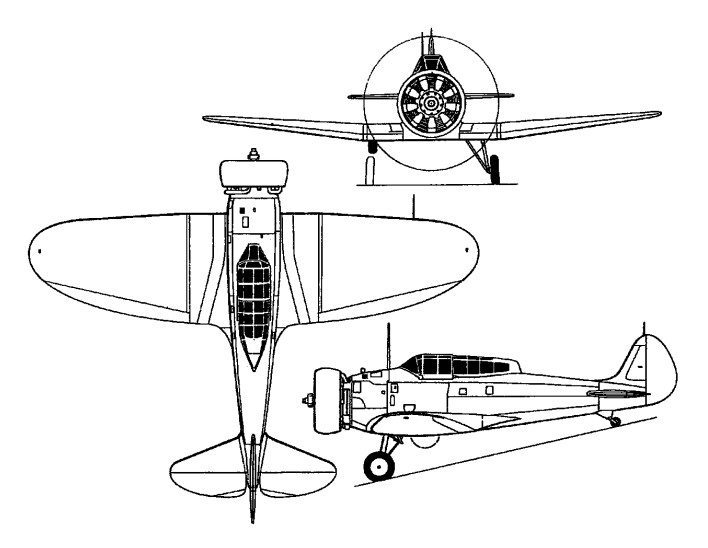
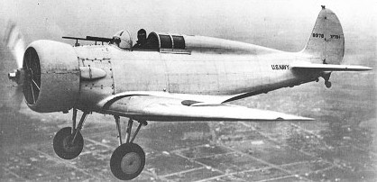
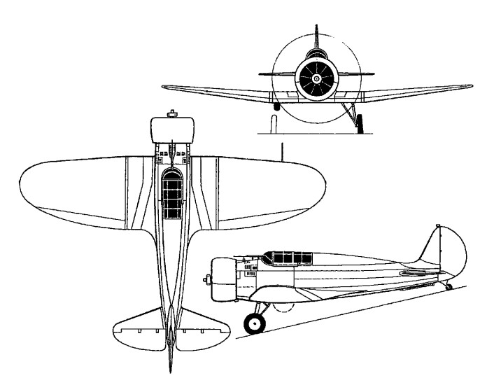
Designed to meet the requirements of a US Navy specification issued on 6 December 1932, the XF7B-1 (Model 273) was the first all-metal cantilever low-wing monoplane single-seat fighter with a retractable undercarriage, and powered by a Pratt & Whitney SR-1340-30 engine rated at 550hp at 3050m. The XF7B-1 featured a fully-enclosed cockpit and was flown for the first time on 14 September 1933. Armament comprised two 7.62mm machine guns. After initial evaluation, the XF7B-1 was returned to its manufacturer to have split flaps and a longer-chord engine cowling fitted. Subsequently the enclosed cockpit gave place to an open cockpit. The US Navy considered that the XF7B-1 offered inadequate view and too high a landing speed for shipboard operation, and the sole prototype was scrapped after, in March 1935, the fighter was inadvertently stressed to 12.1g (although the designed load factor was only 9.0) when the pilot pulled out of a 668km/h dive too abruptly following collapse of the windscreen.
Engine: Pratt & Whitney SR-1340-30, 550hp at 3050m Take-off weight: 1656 kg / 3651 lb Empty weight: 1262 kg / 2782 lb Wingspan: 9.73 m / 31 ft 11 in Length: 8.41 m / 27 ft 7 in Height: 2.26 m / 7 ft 5 in Wing area: 19.79 sq.m / 213.02 sq ft Max. speed: 375 km/h / 233 mph Range: 1207 km / 750 miles
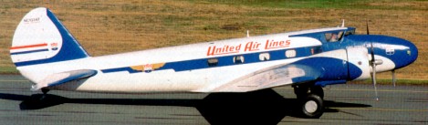
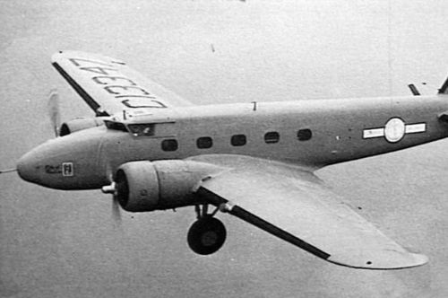
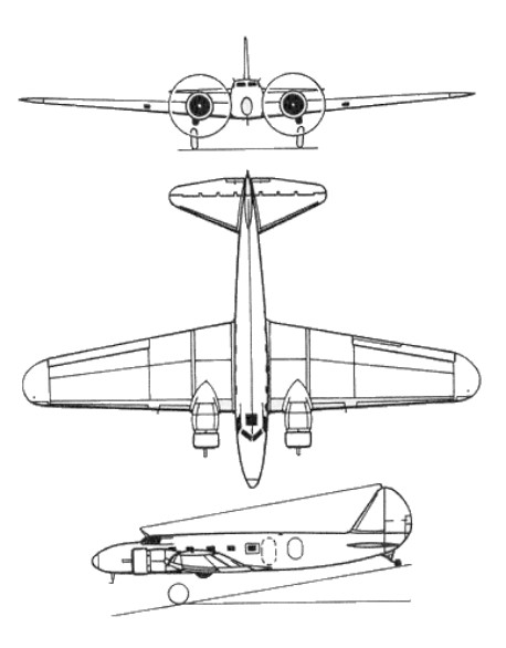
Derived via the design of the Model 200 Monomail and Model 215 bomber, each of which had a cantilever monoplane wing, Boeing flew the prototype of a new civil airliner which was identified by the company as the Boeing Model 247 on 8 February 1933. A streamlined low wing monoplane, powered by two 550 hp Pratt & Whitney radial engines, it had retractable landing gear and was the first transport aircraft to have a de icing system for wings and tail unit. Variable pitch propellers gave maximum efficiency for take off and cruising flight, and control surface trim tabs enabled the pilot to ‘balance’ the aircraft so that an automatic pilot could control the machine for long periods. It was also the first twin-engined monoplane airliner able to climb with a full load on the power of only one engine. With accommodation for a pilot, copilot, stewardess and 10 passengers, sixty examples of the Model 247 were ordered ‘off the drawing board’ to re-equip the Boeing Air Transport System, shortly to become a major limb of United Air Lines, and another 15 were ordered subsequently for companies or individuals.
The Boeing 247 entered service with United Air Lines in March 1933, with a trans-continental flight time of under 20 hrs. The Boeing 247 entered service with National Air Transport (one of the companies under the United Air Lines umbrella) on June 12, 1933. United took delivery of 59 of the 61 247s built, plus 10 of the 13 improved 247-Ds; earlier 247s were modified to this standard. The sole 247-A was used by the United Aircraft Corp as an executive aircraft.
United bought the 60 Boeing 247’s for $4,500,000.
One built for Roscoe Turner and Clyde Pangborn (to compete in the England-Australia ‘MacRobertson’ air race of 1934) was provided with fuselage fuel tanks instead of the standard airline cabin equipment, and introduced NACA engine cowlings (to reduce drag) and controllable-pitch propellers with optimum settings for take-off and cruising performance. These improvements were incorporated retrospectively on most airline Model 247s, thus elevating them to Model 247D standard.
In the 1936 a Chinese Purchasing Commission approached Boeing for a variant of the Boeing 247D to be built. Designated Model 247Y, the militarised variant had an upper rear gunner position, forward-firing guns in the nose, plus under wing bomb carriers. Kept highly secret, only the one is believed built.
Boeing 247-Y 12 Feb 1937 at Boeing Seattle
When the USA became involved in World War II in late 1941, these Model 247Ds remained in airline use, and 27 of them were impressed for service with the USAAF under the designation C-73. It had been anticipated that they could be used for the carriage of cargo and troops, but it was discovered that the cabin doors were too small for this purpose. Instead, they were deployed to ferry aircrew and, later in the war, were used for training. In service they were provided with 447kW Pratt & Whitney R-1340-AN-1 Wasp radials. When no longer required in late 1944, they were returned to civil airline service.
NC13347 Boeing 247D, serial n°1729 of United Air Lines
247 Engines: 2 x 550 hp Pratt & Whitney Wasp Length: 51.3 ft / 16.25 m Wing span: 74 ft / 22.6 m Weight empty: 8,340 lb / 3,780 kg Crew: 2 Pax cap: 10 Max cruise: 171 mph / 275 kph Ceiling fully loaded: 18,500 ft / 5,650 km
247D Engines: 2 x Pratt & Whitney R-1340 Wasp S1H1-G, 550 hp, 410kW Props: Hamilton Standard hydromatic Wing span: 74 ft 0 in / 22.56 m Wing area: 77.6 sq.m / 835.28 sq ft Length: 51 ft 4 in / 16.25 m Height: 12 ft 1.75 in / 3.7 m) Empty weight: 4148 kg / 9145 lb Max TO wt: 13,650 lb / 6197 kg Max level speed: 202 mph / 324 kph Cruise speed: 304 km/h / 189 mph Ceiling: 7740 m / 25400 ft Range: 1199 km / 745 miles Crew: 3 Pax cap: 10
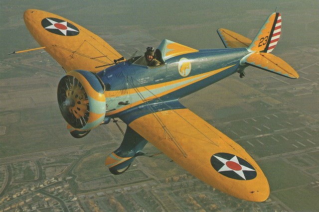
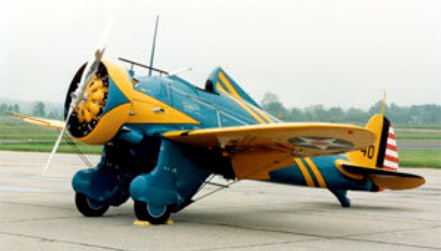
The Model 248 would form the basis for the P-26, and Boeing created a combat aircraft. A low-wing monoplane with the wing centre section built into the fuselage and also mounting the fixed undercarriage. The wing was fabric-covered and wire-braced and armament would consist of two machine-guns.
After examination, USAAC officials decided that the Model 248 incorporated what they wanted, but there was no budget for a new aircraft. In order to create flying prototypes, the Air Corps and Boeing devised that Boeing would build the airframes at company expense while the Air Corps would supply Boeing with such items as engines, propellers, armament, instruments and other equipment. In a normal military aircraft contract, these items would be supplied to the manufacturer as government furnished equipment (GFE).
This arrangement was mutually advantageous – Boeing could build a new design without going bankrupt while the Air Corps would get a new fighter to test virtually free.
Boeing Project Engineer Robert Minshall started work on the Model 248 during September 1931. The aircraft was given the military designation XP-936. Assigned by Wright Field, this designation meant that the Model 248 was the 936th experimental design (military or civil) to be evaluated by Wright Field. A contract for the first three XP-936 aircraft was signed on December 5, 1931.
Since the aircraft was not being developed to strict military guidelines, Boeing was given a free hand, which meant that the aircraft could be designed and built in a much shorter time period. Construction began in January 1932 and Boeing designers moved into the production areas where drawings could be quickly converted to hardware.
The first XP-936 was completed in little more than 70 days. In order to save more time, the aircraft was not fitted with armament, and test pilot Les Tower took the new aircraft into the air on March 10, 1932.
Flight testing also proceeded at a rapid pace (all structural stress testing was still on paper) and the aircraft showed better performance that the P-12F biplane. After limited flight testing, the aircraft was accepted by the USAAC on April 25 at Wright Field, where more advanced testing by a number of Air Corps pilots would take place.
The three XP-936s should have carried civil registrations. However, they were delivered in the military style paint of the day with XP-936 painted on the airframes, apparently in an effort to make the civil aviation authorities think they were in fact military aircraft.
The second XP-936 had been selected for structural testing. These test aircraft were usually non-flying examples, but this example flew from the outset and was delivered by air to Wright Field. Departing Boeing Field on April 22, the aircraft was flown by Lt. L.H. Dawson – another odd procedure since the aircraft was still Boeing property and probably should have been flown by a company test pilot. Once at Wright, the airframe was statically tested (probably to destruction) and it is very unlikely that the second XP-936 ever flew again.
For the third XP-936, the Air Corps determined that this example would be service-tested by USAAC pilots. Accordingly, the machine went to Selfridge Field in Michigan, departing Boeing on May 6. Once again, the aircraft was flown by a USAAC pilot – Maj. G. Brower and it went to the Ist Pursuit Group where pilots from the group’s three squadrons put the XP-936 through a rigorous flight schedule.
On June 15, 1932, the three prototypes were officially taken over by the Air Corps with the signing of a purchase contract. Army officials noted that the aircraft was an improvement over previous pursuits, but noted their opinion in cautious language since funding was in such short supply.
The three aircraft were given the military designation of XP-26. While test flying the aircraft, 1st PG pilots noted some negative aspects that would have to be corrected, including slow throttle response, long take-off and landing roll, and high take-off and landing speeds. Boeing felt it could make changes in a timely manner and the Air Corps managed to get funding for the new P-26 added to the 1932 Fiscal Year Budget.
The three XP-936 prototypes were essentially handbuilt, so a more economical way of building the fighter was required. Because the P-26 had few straight lines its fuselage had to be covered using long horizontal aluminium strips, beginning at the bottom of the fuselage, each strip overlapping slightly and thus producing a “shiplap” effect.
Stress analysis being a new art, most builders incorporated excessive strength. The P-936’s wing was good for +12g and -4g. When the wing was loaded while inverted it withstood 5g without failure. The flying wires reached +14.25g before failing. The Boeing 109 aerofoil was used.
The wing comprised a centre section integral with the fuselage and carrying the undercarriage and a bomb rack, and two removable outer panels based on two spars of builtup flat sheet aluminium. A generous number of ribs of built-up rolled hatsections and short aluminium tubes contributed to the wing’s strength. A thin sheet-aluminium skin was riveted to the wing structure. The XP-936s had brazier-head (flattishdomed) rivets, but production aircraft had flush riveting to reduce drag. Most of the skinning was anodised to protect against corrosion.
The XP-936’s tailplane began to fail at 90 per cent of its design load (which was 2531b/sq.in), and had to be greatly reinforced. The fin was tested to 130 per cent of its design load (189.61b/sq.ft), Unlike the wing, the tail was of unbraced cantilever design, the all-metal units being built in the spar-and-rib style. Aluminium channel was built into a hinge-line spar, and there was also a diagonal spar. There was no solid leading edge; the upper and lower skins were joined by flush riveting. The ribs did not act as compression members, but were essentially spacers for the aluminium skins.
The control surface hinge lines were channel spars, and pressed aluminium diagonal ribs carried the top and bottom aluminium skins, which were riveted together at the trailing edge. The elevators incorporated the first use in the USA of trim tabs to adjust longitudinal trim in flight. Each aileron had a groundadjustable aluminium trim tab.
The removable welded -steel -tube engine mounting was fixed to the first fuselage bulkhead. Hydropress dies were used to form the smoother panels ahead of the firewall.
The welded steel-tube undercarriage incorporated a rigid ‘V’ structure attached to the wing root spars that also provided an anchor for the flying wires. Boeing-built oleopneumatic shock struts were used. Each leg held just the inboard axle end, allowing easy removal of the wheel and tyre, The undercarriage was faired with aluminium, and the wheel spats were press-formed from aluminium sheet and attached to the shock strut so that the spat moved with the strut. The undercarriage could become unstable with the flying wires loosened or removed, so a spreader bar was added between the undercarriage legs.
Fuel was carried in a main tank in the fighter’s belly, holding 55 US gal, plus removable 26 US gal tanks in each wing root. There was an 8 US gal oil tank in front of the first bulkhead. The cylinders were encircled by a Townend ring to reduce drag.
The two 0.30in-calibre Browning machine-guns could be changed for a 0.30in gun on the port cockpit floor and a 0.50in gun to starboard. The smaller-calibre weapons had 500 rounds each, but only 200 rounds were provided for the 0.50in gun. A Type A-3 underfuselage munitions rack carried a range of light ordnance.
Once contracts were in place and construction on the P-26A had started, few problems were encountered and production gathered pace. By June 1934 all 111 production examples had been delivered.
The first production run averaged out at $9,999 for each aircraft, but this did not include the government furnished equipment (GIFIE) such as engines, radios and armament. The rapid delivery also meant that problems inherent with the design had not really been rectified.
While squadrons were getting used to the type, the global financial and political situation was changing. American expenditure on military aircraft had risen from $25m for the fiscal year 1925 to $69m for FY 1931, and increasing political tensions around the world had led to an arms race. During 1935, the Italian leader Benito Mussolini had given orders to attack Ethiopia while Hitler made his new Luftwaffe public.
XP-936
In the USA the new Roosevelt administration was backing drastic social reforms to ease the nation out of the grips of the Great Depression, and also allocating unprecedented funds for military aviation. The Baker Board recommended that the Air Corps increase its inventory to 2,320 aircraft while a General Headquarters Air Force (GHOAF) was established for operations not dependent on ground forces. Officially begun in March 1935, the GHOAF had been structured so that its aircraft could be concentrated for a military attack in any direction.
The GHOAF comprised all the attack, bomber and fighter units in the USA, but excluded observation units and five PGs deployed overseas. Between June 1932 and January 1940, total Air Corps strength consisted of 15 Groups. The general staff in charge of operations saw little use for additional aircraft and rarely expended all the funds assigned. Into all this planning came the force of Peashooters.
The aircraft went to the l st, 17th, and 20th PGs. For the pilots, their only training came in the form of reading extremely condensed pilot’s notes. Tactics related mainly back to lessons learned during World War One.
One major design problem became apparent on February 22, 1934, when Lt Frederick Patrick was killed when his P-26A, serial 33-46, tipped over during a forced landing. The aircraft received little damage but the headrest broke off and Patrick’s neck was broken. The fleet was grounded while Wright Field and Boeing worked on a fix. A new headrest, some 8 in higher, that could resist a 27,6001b vertical load, was developed and installed on 33-56, which had yet to be delivered. All aircraft at the factory were thus modified and deliveries resumed on March 27. All other aircraft were modified in the field, work being completed by May 21.
The aircraft’s tailplane was easily damaged by rocks and gravel when operating from rough fields, so sheet rubber was added to the lower leading edge of the unit, leading to speculation that the P-26 was fitted with de-icers. It wasn’t.
Pilots converting from biplane fighters found the Peashooter’s landing speed – 82 mph. – to be disconcertingly high. The National Advisory Committee for Aeronautics (NACA), Boeing and the Air Crops worked on the problem and developed four different types of flaps which were tested in the wind tunnel at Langley Field, Virginia, using 33-56 as a guinea pig. It appears that the least effective unit was chosen by Wright Field, installed on 33-28 which, when flight tested, crashed because the flaps blanked out the tail surfaces during approach (which NACA had predicted).
Boeing developed a flap system that was complex and expensive to produce. These were tested on the first of the export variant, the Model 281, which was sent to Wright Field for testing. These flaps brought the landing speed down to 73 mph and the Air Corps accepted the design. In May 1935, Boeing began to receive the P-26 fleet for flap fitting. The first unit to arrive was the 17th PG from March Field, California. This unit had been redesignated as an attack group and would soon give up the Peashooters for more effective equipment. All the P-26s had been fitted with flaps by November 1935.
Pilots who undertook high-g manoeuvres found that certain aircraft were developing skin wrinkles between the tail and cockpit. Boeing recommended a strengthening of the fuselage. Part of the skin was removed so that structural modifications could be made. Also, a new tailwheel assembly was added to improve ground handling.
Although the P-26 was used mainly for daylight operations, pilots complained about exhaust glare in flight during night or twilight conditions. Accordingly, the exhaust system was modified to prevent this problem. Also, pilots found that the pitot tube on the starboard wing would vibrate heavily in flight. Boeing reduced the size of the tube, but this gave inaccurate airspeed readings and a final fix was accommodated by adding a more rigid pitot tube.
Once in service, the P-26 demonstrated a problem that could not be fixed, however. The narrow undercarriage, high centre of gravity and spongy shock absorbers resulted in many nose-overs. The remedy was to issue bulletins to pilots on how to avoid this occurrence.
With the aircraft distributed to the three Groups, the usual flying took place with units practicing tactics, formation flying, cross-country flights and participating in war games. The P-26 was quickly eclipsed by the Seversky P-35 and Curtiss P-36 and Peashooters began to go to second and third-line units.
During 1938, the 18th PG received at least 42 P-26s for the defence of Hawaii. Although these machines were theoretically phased out by the time of the Japanese attack on Hawaii on December 7, 1941, at least a dozen were present at Wheeler Field. One account states that none of these aircraft received damage; another proclaims that several were destroyed or damaged.
The Peashooter apparently did not take any part in the defence of Pearl Harbor, and those remaining may have been retained as hacks or advanced trainers. Thus, the service life of the Peashooter was brief and while the aircraft introduced new features it was also a design that was obsolete from the start. It was also the last production fighter design built by Boeing.
Boeing decided to create an export variant of the P-26A as the Boeing Model 281. This was essentially a standard P-26A airframe with equipment added per the customer’s order. Reasoning that these aircraft would be operated off fields more primitive than the American military, Boeing made a study on how to reduce the aircraft’s comparatively high landing speed. The first Model 281 (c/n 1959, carrying American civil registration X12771), made its first flight on August 2, 1934. The aircraft was painted in standard Air Corps colours of Olive Drab and Chrome Yellow. After several flights, Boeing installed split trailing-edge flaps which reduced the landing speed. The Air Corps took note and accordingly had their P-26As retrofitted.
At this time, there was a great deal of upheaval in China as various factions fought for control – all the while being watched by Japan. Using company money, Boeing sought out further interest from the Chiang Kaishek government. Meanwhile, the Model 281 was tested with revised wheel fairings more suited to primitive environments and the aircraft was tested with Goodyear Airwheels for use on undeveloped fields.
An order for ten Model 281s for China was finally received, and much of the purchase money was raised by the Chinese community in America. Deliveries of the Model 281 were made between December 2, 1935, and January 5, 1936.
The Chinese 281s were dismantled after test flights and then sent by ship to China where they were reassembled and test-flown. The aircraft were based at Chuying airfield, near Nanking. By this time, invading Japanese forces had begun to overwhelm Chinese forces, and Nanking was an inviting target for “Nell” bombers operating from Taipei on Formosa (now Taiwan).
It is not known if the Japanese were aware of the ten Model 281s based at Nanking, or whether some of them were being flown by mercenary pilots. On August 20, 1937, a force of “Nell” bombers set forth to attack Nanking, all with inadequate defensive armament and without fighter escort (the fighters simply did not have the range). As the bombers arrived over Nanking, they were met by the 281s. Six of the Mitsubishis were destroyed and one of the 281s received light damage. The Japanese seemed to be willing to accept the losses and kept sending the bombers to attack Chinese targets. After securing bases on the mainland, the bombers were able to conduct raids deep into China.
Although records are incomplete, it appears that the Boeings continued to score successes. However, lack of spare parts and the introduction of Japanese fighters into combat meant that when Nanking fell on December 13, 1937, none of the Boeings was airworthy.
During this troubled period, Spain also took interest in the Model 281 and X12275 (c/n 1962) was shipped across the Atlantic and reassembled for test flying at Barajas airfield near Madrid on March 10, 1935. A contract had originally been signed by the Direccion General de Aeronjutica on January 16, 1935, with Boeing and an individual named Alfonso Albeniz. The fighter was demonstrated to the Spanish by company test pilot Les Tower with Boeing vice-president Erik Nelson in attendance.
The Spanish liked the Model 281, but they did not like the price. Accordingly, during June 1935, the Spaniards contracted with Hawker Aircraft in the UK for 50 Fury biplane fighters to be built under licence by Hispano-Suiza.
The Model 281 did not return to Seattle but remained at Barajas. When the Spanish Civil War started on July 17, 1936, the 281 was flown to Cuatro Ventos airfield near Madrid. The aircraft had arrived in Spain with no armament and no synchroniser gear so the Spaniards modified the aircraft to mount two British Vickers machine-guns in pods under the wings, after which the Republican Boeing began flying combat missions.
American mercenary pilot Eugene Finnick described the Boeing as “an old rattletrap”. However, the Boeing kept operating and by mid-October 1936 it was one of only three operational fighters left at Getafe. On October 21, it was shot down in a battle with three Fiat CR.32s over the airfield. Pilot Ramon Puparelli escaped by parachute, but the combat career of the sole Spanish 281 was most definitely over.
Sometime later, the Spanish embassy in Paris paid Wilbur Johnson (a Boeing representative) $20,000 for the aircraft.
In addition Panama and Guatemala received ex-USAAC P-26. The ones left by the US army to the Guatemalan Air Force were sold for $1 each as PT-26; that is, trainers, to allay political misgivings. They were very manoeuvrable, and were named “mosquitos” locally, because the peculiar sound made by their motors. They were still in service by 1954.
In total, only 136 P-26s were built.
The Model 224 would later be refined into the Model 264 and the Air Corps would eventually acquire three as the P-29.
Replica: WAR aircraft P26 Peashooter Mayocraft Inc P26 Peashooter
Variants: P-936 USAAC experimental designation for first three Model 248 aircraft. Two flown, one used for static testing
P-26 Designation applied to P-936 on June 15, 1932. USAAC serials 32-412-414
YIP-26 Service test designation for P-936
XY1P-26 Applied in August 1932 as an apparent paperwork combination of the above designations
Y.26 Standard designation applied to the first aircraft
P-26A First production order for 111 examples. USAAC serials 33-28-138
P-26B Two of the 25 aircraft added to the above order fitted with fuel-injection engines and wing flaps. USAAC serials 33-179 and 33-180
P-26C 25 aircraft added to the P-26A order with minor differences. After about a year of service, all were modified to P-2B standard. USAAC serials 33-181, 33-183-203
Model 281 Export version of P-26A to China and Spain. Boeing c/ns 1959-1962,1965-1972
RP-26 Designation applied on October 22, 1942, to surviving USAAC P-26s to indicate they were obsolete and restricted from combat action
ZP-26 Order issued on December 11, 1942, regarding P-26As too old to fit into the RP designation
PT-26A Paperwork designation applied for political reasons to the examples supplied to Guatemala
Specifications:
XP-936 Engine: Pratt & Whitney R 1340-1, 525 hp Wingspan: 27 ft 5 in Length: 23 ft 9 in Height: 7 ft 6 in Wing area: 149.512 sq.ft Max take off weight: 2789 lb Weight empty: 2120 lb Fuel: 50-106 USG Max. speed: 227 mph at 6000 ft Cruising speed: 193 mph Landing speed: 73.5 mph Ceiling: 27800 ft Climb: 2230 fpm Crew: 1
Boeing P-26A Peashooter Engine: 1 x Pratt and Whitney R-1340-27, 600hp. Length: 23.82ft (7.26m) Wingspan: 27.95ft (8.52m) Height: 10.40ft (3.17m) Empty Weight: 2,273lbs (1,031kg) Maximum Take-Off Weight: 3,012lbs (1,366kg) Fuel: 52-107 USG Maximum Speed: 227mph (365kmh; 197kts) Cruise: 199 mph Landing speed: 82.5 mph Maximum Range: 360miles (579km) Rate-of-Climb: 2,360ft/min (719m/min) Service Ceiling: 27,395ft (8,350m) Armament: 2 x 7.62mm machine guns Accommodation: 1
Boeing 281 Engine: 1 x Pratt and Whitney R-1340-33, 600hp. Length: 23.82ft (7.26m) Wingspan: 27.95ft (8.52m) Height: 7 ft 10.5 in Empty Weight: 2,354lbs Gross weight: 3039 lb Maximum Take-Off Weight: 3,390 lb Fuel: 55-107 USG Maximum Speed: 235mph at 6000 ft / 215 mph at SL Cruise: 210 mph Landing speed: 68 mph Maximum Range: 360miles (579km) Rate-of-Climb: 2,360ft/min (719m/min) Service Ceiling: 28,200 ft Armament: 2 x 7.62mm machine guns Accommodation: 1