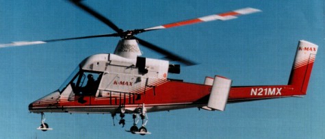
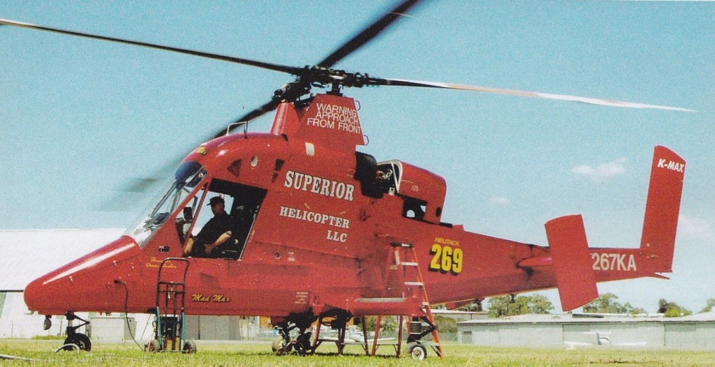
By July 1997, 23 K-Max had been built. Overall, the fleet had accumulated 26,000 hrs, with the highest time example reaching 4000 hr since delivery in October 1994. The production rate was six per year.
Kaman K-Max Engine: Textron Lycoming T 5317 A1, 1479 shp Instant pwr: 1118 kW. Length: 51.837 ft / 15.8 m Height: 13.583 ft / 4.14 m Rotor diameter: 48.228 ft / 14.7 m Max take off weight: 11501.3 lb / 5216.0 kg Weight empty: 4701.1 lb / 2132.0 kg Payload: 2722 kg Max. speed: 100 kts / 185 kph Max cruise: 100 kts Service ceiling: 25000 ft / 7620 m Crew: 1 Payload: max 2700kg ext.
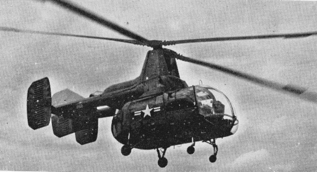
The basic Seasprite design won a US Navy design competition during 1956 for a high performance, all-weather, multi-role utility helicopter, then designated the HU2K-1. The prototype Seasprite first flew on July 2, 1959 and an initial contract was for four prototypes and twelve production Kaman helicopters, now known as the UH-2A and given the name Seasprite. The initial production UH-2A models were powered by one engine, however, they were equipped for IFR operations and a total of 88 were ultimately built. The UH-2B was VFR equipped and 102 in total were built with fully retractable forward mounted main landing gears.
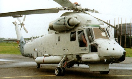
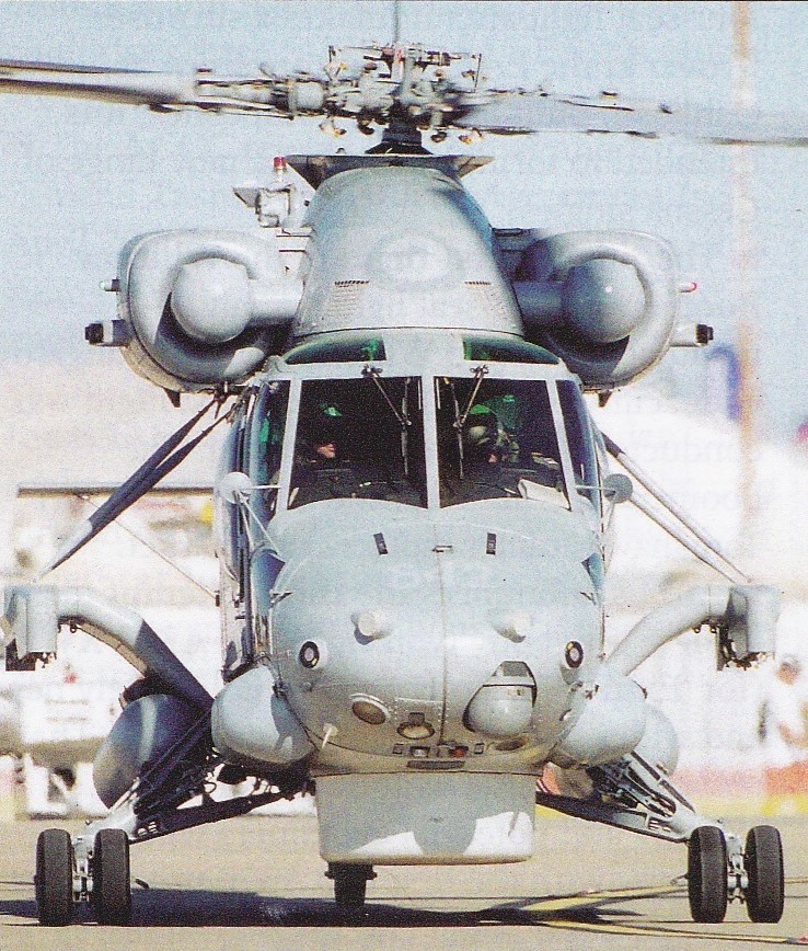
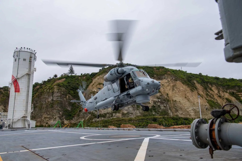
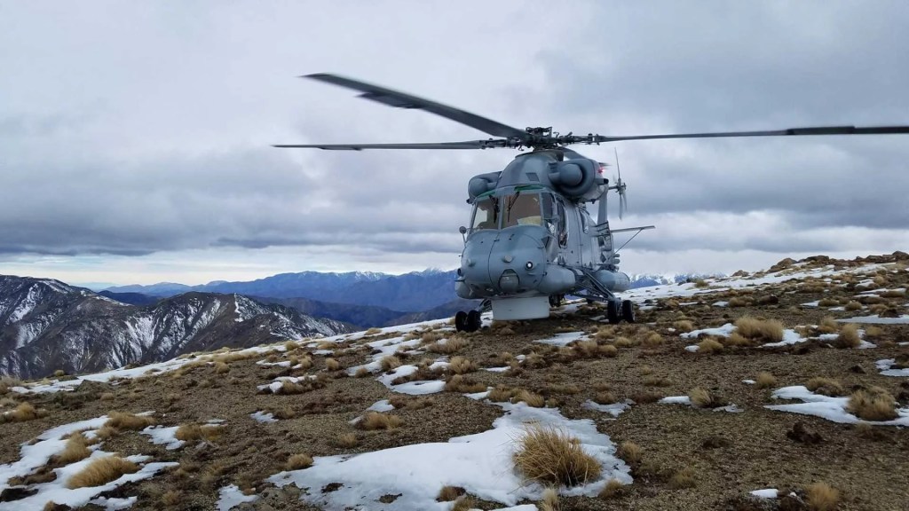
The UH-2A and UH-2B could each carry a 1814 kg (4,000 1b) slung load or 11 passengers, and work in planeguard, SAR, fleet reconnaissance, vertrep (vertical replenishment) and utility transport duties, operating from many surface warships as well as at shore bases. The UH-2C, a re-definition of the UH¬2 and UH-2B, was the first to be fitted with two engines. From 1967 Kaman converted of 88 earlier SH-2D Seasprites to the SH-2F version in May 1973. The SH¬2F “Super Seasprite” has “up-rated” engines and the LAMPS system (light airborne multi¬purpose system). Fifty-two new SH-2Fs were delivered from 1981. Deliveries of the SH-2F version began in May 1973 after completion of 190 early-model UH-2A/B SAR helicopters. Before manufacture was suspended 88 SH-2Fs were built. Deliveries from resumed production began in 1983, and Seasprites delivered after October 1985 have an increased gross weight of 6,124kg, compared with the 5,805kg of earlier SH-2Fs. With a crew comprising pilot, co pilot and sensor operator, the SH 2F can carry MASW gear including Canadian Marconi LN 66HP surveillance radar, towed ‘bird’ for the AN/ASQ 18 MAD, AN/ALR 64 passive detection receiver, Difar passive and Dicass active sonobuoys, and comprehensive nav/com and display systems. The 4,000 1b (1814 kg) cargo ability remains, and a 600 1b (272 kg) rescue hoist is standard. Production of the twin-turbine SH-2F Seasprite Mk.1 light airborne multipurpose system (Lamps I) restarted in 1982, to meet a US Navy requirement for up to 60 helicopters to equip vessels too small for the SH-60B Seahawk. Up to FY1986 54 new-build SH-2Fs had been authorised, and six more were requested in FY1987. These will join some 79 SH-2Fs from earlier production which were still in service at the beginning of 1986, some of which were upgraded SH-2Ds. Ten new SH-2Fs were delivered in 1986. A re-engined version of the Seasprite, the YSH-2G, flew on April 2, 1985, powered by two General Electric T700 turboshafts similar to those used in the SH-60B and giving improved range, reliability, and maintainability. Evaluation of the prototype YSH-2G was completed in 1985. In general terms, the SH-2G is a retrofit of the SH-2F model. The heart of the SH-2G(NZ)’s weapons platform is its Litton ASN-150/1553B tactical data system, APS-143 (V) 3 radar, Doppler APN-217 (V) 6 radar, FUR Systems AAQ-22 forward-looking infrared system, and Litton Amecon LR-100 electronic support measures ESM sensor system. These systems are operated from the two pilot analogue cockpit, with the observer (air¬borne warfare officer) occupying the left-hand seat. The helicopter’s missions are primarily surface sur¬veillance and anti-surface warfare, where the helicopter will conduct surveillance tracking and targeting and, if necessary, engage surface targets, but it is also capable of sub-surface weapon delivery and utility support, including search and rescue, replenishment, medical evacuation, naval gunfire spotting and troop transport for boarding operations.
SH-2G(A) Super Seasprite
In May 2006 the Royal Australian Navy’s fleet of 11 SH-2G(A) Super Seasprite was grounded with problems with their avionics and electronics systems. Service entry had been delayed by five years due to serious systems integration and software problems.
H-2 experiments included stub wings serving as sponsons and gunship version with Minigun chin turret among other weapons.
Kaman Aerosystems, are powered by two General Electric T700 turbines rated at 1,600 hp each. Measuring 16 meters in overall length with a 13.5-meter rotor diameter, they have a maximum take-off weight of 6,441 kg, a range of approximately 275 nautical miles, and a maximum endurance of around two hours and 45 minutes. Capable of reaching airspeeds near 130 KCAS, they feature a standard crew of three: a pilot, an observer responsible for warfare and mission coordination, and a helicopter loadmaster managing utility operations. Armament options include Penguin anti-ship missiles, Mk 46 torpedoes, and a door-mounted MAG 58 machine gun.
The SH-2G lineage traces its origins to the United States, where the type was developed in the 1980s as a modernized version of the SH-2F for use on naval vessels unable to accommodate larger helicopters like the SH-60B Seahawk. The SH-2G introduced more powerful engines, a reinforced upper fuselage, and improved avionics, including an Integrated Tactical Avionics System (ITAS) and digital automatic flight controls. Despite its eventual phaseout in the U.S. by 2001, the type continued to serve internationally, including with the Egyptian, Polish, and Peruvian navies.
The SH-2G(I)’s design emphasizes multi-role capability, supporting missions such as over-the-horizon surveillance using radar and FLIR systems, anti-ship strike with guided missiles, underwater warfare with torpedoes, as well as disaster response, medevac, and transport operations.
HH-2D Engines: 2 x General Electric T58 GE 8F turboshafts, 1,350 hp each. Length: 38 ft 4 in. Rotor dia: 44 ft. Speed: 168 mph. Ceiling: 22,500 ft. Range: 445 miles.
SH-2F Seasprite Engine: 2 x GE T58 8F turboshafts, 1,350 shp (1007 kW). Installed pwr: 2041 kW. Rotor dia: 13.4 m (44 ft 0 in). Main rotor disc area 141.25 sq.m (1,521.0 sq ft). Fuselage length: 12.3 m (40 ft 6 in), (folded): 11.7 m. Height: 4.72 m (15 ft 6 in). No. Blades: 4. Empty wt: 3193 kg (7,040 lb). MTOW: 6033 kg (13,300 lb). Max speed: 265 km/h (165 mph). ROC: 744 m/min. Ceiling: 6860 m. HIGE: 5670 m. HOGE: 4695 m. Fuel cap (+aux): 1500 lt ( 455 lt ). Range max¬ internal fuel: 680 km (422 miles). Crew: 3. Armament: one or two AS torpedoes (usually Mk 46).
SH-2G Super Seasprite Engine: 2 x GE T700-401. Instant pwr: 1259 kW. Rotor dia: 13.41 m. MTOW: 6124 kg. Payload: 2107 kg. Useful load: 987 kg. Max speed: 141 kts. Max cruise: 136 kts. Max range: 869 km. HIGE: 17,600 ft. HOGE: 14,600 ft. Service ceiling: 20,400 ft. Crew: 3. Pax: 8.
SH-2G(NZ) Engines: 2 x T700 GE-401 gas turbines of up to 1723 shp each, plus one Garret GTCP36-150 APU.
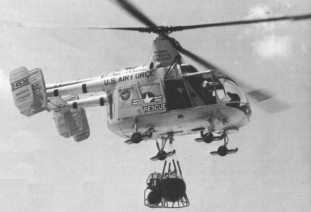
The H-43 was designed extremely compact because it’s inter-meshing rotors. Between 1958 and 1965 some 365 were built.
By late 1960s well over 200 H-43 Huskie turbine-powered rescue helicopters were serving with the USAF.
Kaman HH 43 B Husky Engine: Lycoming T53-L-1B, 848 shp Length: 25.164 ft / 7.67 m Height: 12.598 ft / 3.84 m Rotor diameter: 47.014 ft / 14.33 m Max take off weight: 9161.8 lb / 4155.0 kg Max. speed: 104 kts / 193 kph Service ceiling: 25000 ft / 7620 m Range: 240 nm / 445 km Crew: 1+8
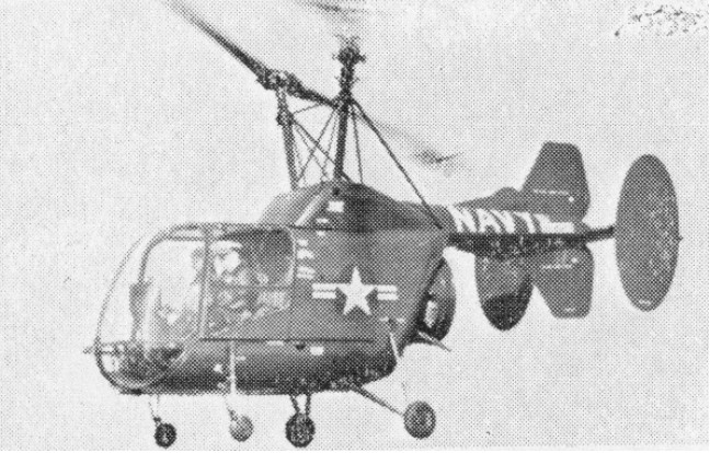
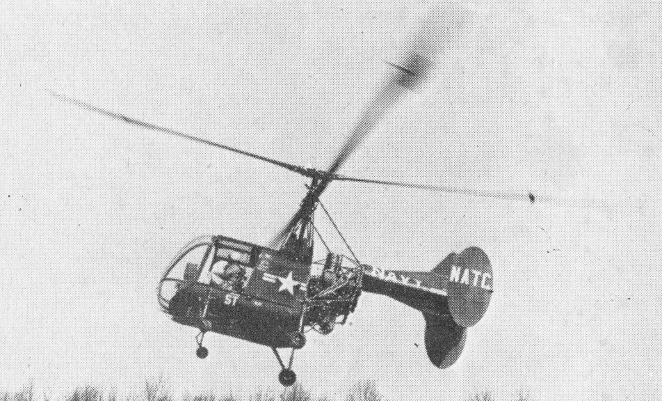
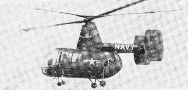
Ordered into production for the U.S. Navy at the same time as the HOK-1“off the drawing board “, the HTK-1 also uses the Kaman system of inter-meshing rotors, controlled through servo flaps.
The HTK-1 was delivered to the U.S. Navy as trainer/ambulance, and also adopted as remote-controlled drone. For ambulance work it can carry a stretcher and medical attendant in its cabin, and two casualties on Stokes litters externally, one on each side.
One HTK-1 has been fitted experimentally with two Boeing T50 gas turbines.
Boeing YT-50-BO-1 powered
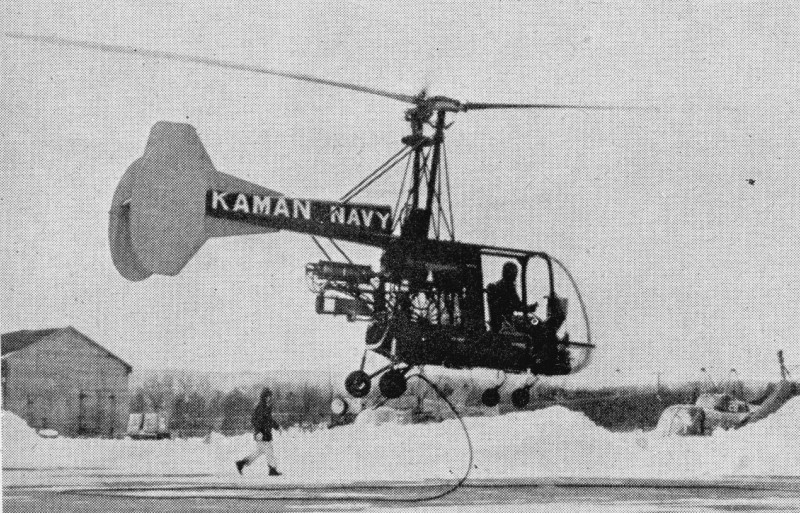
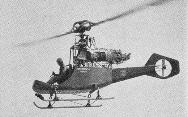
During 1958, Kaman completed a research project in which this HTK-1 was flown on electric power. The 240 hp Lycoming engine was replaced by an electric motor of equivalent power, connected to a ground power source by cable.
HTK-1 electric
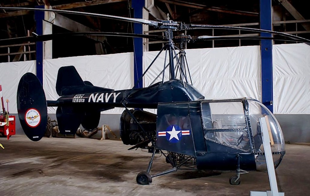
HTK-1 Huskie BuNo. 129313 C/N 422
Twenty-nine HTK-1s were built between 1951 and 1953. Powered by a 240 hp Lycoming O-435-4 piston engine, they served with the Navy at Pensacola until 1957.
HTK-1 Huskie BuNo. 129313 C/N 422
Engine: 235 h.p. Lycoming O-435-4 Rotor dia.: 40 ft Fuselage length: 23 ft Max Weight: 2,750 lb Max. Speed: 75 mph Ceiling: 10,000 ft Typical range: 194 miles at 70 mph with full load Seats: 3
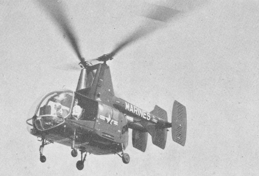
Following evaluation of the Kaman K-225, the US Navy chose the HOK-1 design as best of several submitted in competition for a liaison helicopter. Using the same rotor systems as the K-225, the HOK-1 was put into production off the drawing-board and delivered in quantity to the U.S. Navy and Marines during 1950s. It normally carries four people; but as an ambulance will accommodate two stretcher patients and one sitting patient or medical orderly, in addition to the pilot. Stretcher loading is through the nose, as on the HTK-1.
In service with the U.S. Navy in 1955 as a 4-seat liaison and casualty evacuation helicopter.
As part of a general development programme, several piston-engined helicopters, such as this Kaman HOK-1, were re-engined with gas turbines.
Engine: 800 hp Pratt & Whitney R1340-48 Rotor dia.: 46 ft. Max Weight: 3,500 lb. Seats: 4
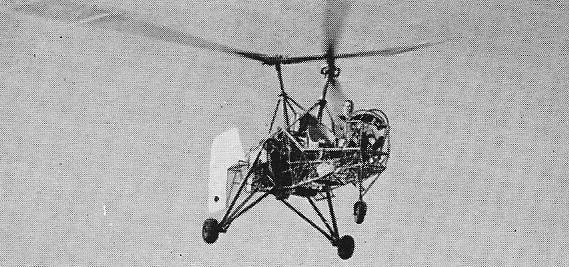
A progressive development of the K-125A and K-190 of 1947 and 1948, Kaman’s second helicopter, the K-225, first flew on 10 December 1951.Kaman put the K-225 into limited production in 1949 as the YH-22.
The K-225 is powered by a 225 hp Lycoming O-435.
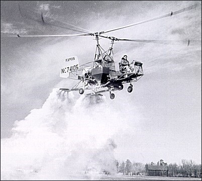
Certified by the CAA, there were eleven K-225s produced and they were used in the crop-dusting role.
As a single-seat crop duster, the K-225 was supplied to the Turkish Department of Agriculture.
Testing by the U.S. Navy influenced the award of contracts for the HOK-1 and HTK-1 to the company.
Under U.S. Navy contract, Kaman fitted a 175-h.p. Boeing YT-50 gas-turbine engine to a K-225, and this was the first helicopter, with turbine-driven rotors, flying on 10 December 1951.
Engine: 225 hp Lycoming O-435 Rotor diameter: 38 ft Fuselage length: 23 ft Height: 11 ft 6 in Empty weight: 1800 lb Loaded weight: 2700 lb Max speed: 73 mph Cruise: 65 mph ROC: 1000 fpm Ceiling: 12,000 ft Range: 194 mi at 65 mph Seats: 3
The Kaman K-17is powered by a Blackburn Turmo 600 turbine engine. This engine drives a Boeing compressor which supplies air to pressure jets at the rotor tips. The K-17 first flew in the Spring of 1958.
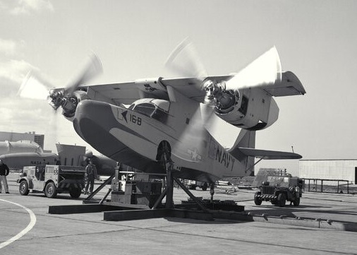
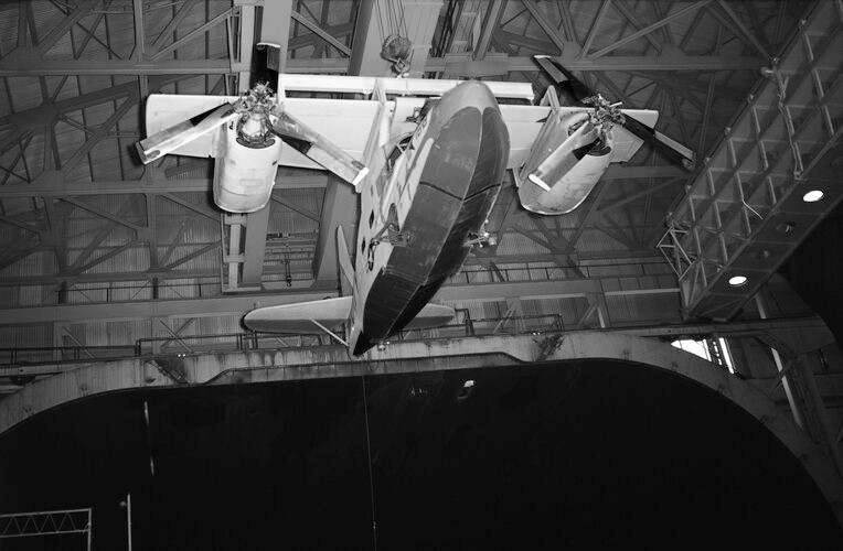
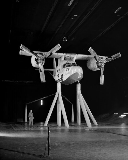
NASA Ames Research Center conducted wind tunnel tests on the K-16B.
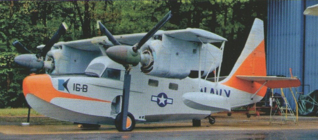
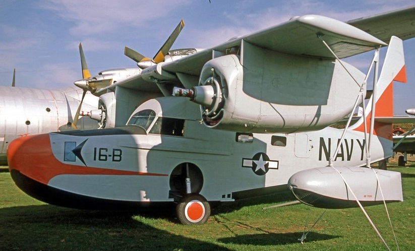
The sole Kaman K-16B is resting in the New England Air Museum, Hartford, Connecticut.
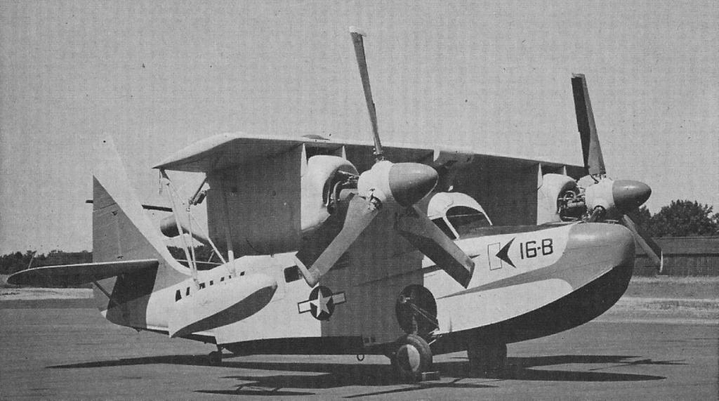
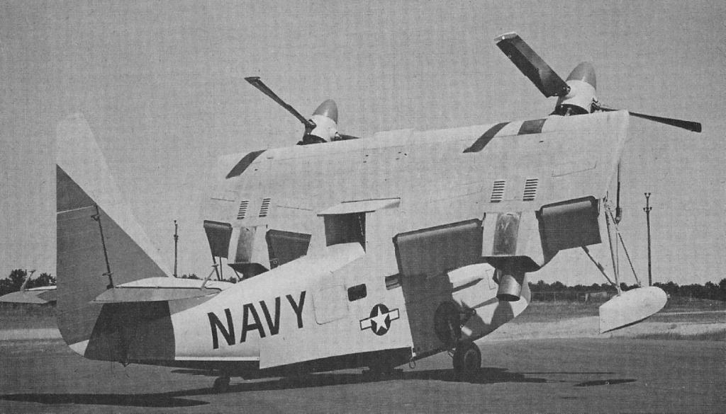
Kaman K-16B tilt-wing STOL research aircraft
Engines: 2 x GE T-58-2A, 1024 hp Wing span: 34 ft Length: 38 ft 4 in Height: 19 ft 3 in Normal gross: 9295 lb Design max speed SL: 211 kt Deign max speed 15,000ft: 215 kt Max ROC: 6000 fpm Vertical climb: 400 fpm Service ceiling: 36,000 ft Hover ceiling: 2400 ft Range w/1000lb fuel: 205 nm Max range speed: 130 kt TO to 50 ft 12,000 lb: 514 ft Mean aerodynamic chord flap extended: 112.1 in Prop Airfoil: NACA 16-500 Prop diameter: 14 ft 10 in Prop blade chord: 18 in Flapping hinge radius: 9.2% Blade pitch range: 15-45 deg Max wing tilt: 50 deg Wing flap deflection: 60 deg Rotor blade flap collective: 13 deg max Rotor blade flap cyclic: +/- 25 deg
One of the more original KA Kalinin designs was the experimental K-12 or VS-2 (Russian: Калинин К-12 (ВС-2)) tailless aircraft, which had its origins in a request made on July 4, 1932 by the VVS RKKA to the Kharkov Experimental and Serial Aeronautical Construction Factory (JAZOSS) within the framework of the process of modernization which began in February.
It was necessary to replace the Polikarpov R-5. The technical requirements for the new model were dictated by the NII VVS as a multifunctional aircraft for military purposes under the name VS-2, an acronym for V oickovoi Samoliot -2 or Military Aircraft -2.
The K-12 was designed as a light bomber, reconnaissance aircraft, photographic reconnaissance and even light transport aircraft and ambulance. The required speed had to exceed 250 km/h at an altitude of 3,000 meters and the radius of action was 350 km.
By April 1933, the first conceptual drawings of the model were delivered in three versions with the use of three power plants: M-22, M-49 and M-52.
These versions included a traditionally designed aircraft, a twin tailcone structure aircraft, and a third that was close in outline to a flying wing, but featured a small-area horizontal tail surface, located close to the fuselage, thus which was known as the “short tail version”.
Kalinin convinced the head of the NII VVS VK Lavrov to choose the last variant. In his opinion, this variant should have the greatest maneuverability and the best defensive composition due to the absence of firing dead zones. The works began with the tests of some models in the wind tunnel of the Kharkiv Aviation Institute.
After an initial analysis at the NII VVS, the VS-2 project was not approved. It was argued that the project was incomplete and the aircraft overloaded. The use of the M-52 engine according to the data provided by the TsAGI would not be included in the experimental construction plan and the rupture of the crankcase during the tests required important modifications, so it was not feasible to project any aircraft on the basis of that power plant.
The only interesting thing according to the VVS leadership was the flying wing scheme. At that time, both in the USSR and abroad, this scheme attracted aircraft manufacturers, but only the most daring faced it. Too many technical aspects had to be taken into account and, despite the fact that the calculations showed that such a configuration would bring important advantages in terms of speed, manoeuvrability and defensive ease, the risk was too great.
In September 1933 JAZOSS submitted a second VS-2 variant for study. By then the project had already received the K-12 index in the KB. This project was also close to the concept of a flying wing, but kept the tail unit. The engines were located on the sides of the fuselage, inserted into the leading edge of the cantilever wings. The wings had a rectangular shape in the center plane, with trapezoidal consoles with arrows on the leading edge and the trailing edge straight, following the line of the center plane.
Single spar stabilizers were attached to either side of the fuselage, just aft of the wing trailing edge. To reduce the landing speed, Northrop – type surfaces were placed along the entire length of the wingspan. The wing leading edge featured two section slats, the outer ones featured automatic operation and the inner ones were pilot controlled. Aerodynamic surfaces were also located on the surface of the intrados, which were extended during landing, increasing the wing surface by 15-20%.
This version would lead to the definitive variant without a tail and with trapezoidal wing consoles, with vertical surfaces used as rudders located at the ends.
The civil version of the model was calculated for 11 passengers and a postal variant accommodated six. The plane could be disassembled to be transported in rail cars.
The novelty and complexity of the project forced a detailed analysis of the data presented. At that time in the USSR there was no experience in similar configurations or theoretical bases that would allow comparing the calculations presented. For these reasons, the analysis of the TsAGI and a group of renowned specialists who had to study the material presented were requested.
During the analysis of this proposal, a series of criteria were issued, which prevented an effective assessment of the calculations presented. The selection of the model geometry was considered to lack a theoretical basis. The selection of the shape and surface of the empennages and the aerodynamic characteristics of the machined surfaces of the wing had not been calculated. The static coefficients were not presented with the project, nor were wind tunnel tests carried out to confirm the correct selection of this composition. On the other hand, the performance calculations were presented without a specific definition of the propeller to be used, so it is impossible to verify them.
Problems were found in the calculation of the balance and weight of the aircraft, its payload capacity, fuel and oil and many other aspects, so it was considered that the results of the calculations presented did not correspond to reality. It was pointed out that the aerodynamic calculations for the M-22 and M-52 engines had been made on the basis of the same weight, which was not true.
As a result of the analysis, the report considered that the conceptual project presented by the JAZOSS with two M-22 engines was prospective for both military and civilian use, for which reason it was concluded that it could be approved in general, excluding the dimensions and position of the empennages and ailerons, which still needed to be tested in the wind tunnel. The installation of the M-22 engines in the VS-2 was considered temporary, until the M-52 engines were ready. The presentation of a landing gear on skis was also established as a condition for the state tests.
Another report, presented on October 29, 1933, clearly highlighted that this new project had too many little-studied aspects such as its general configuration, the wing without tail, the Northrop planes and the slats. There were no clear calculations of their independent behavior and even less of their work together. It was also written that according to the opinion of the specialists the new scheme would not bring any gain from the aerodynamic point of view. Answering concerns about stability and landing would still require a lot of testing in the wind tunnel. For all these reasons it was proposed to build only a model on a smaller scale with purely experimental objectives.
Lastly, the report presented by Ilyushin considered that the military scheme of the model should not be approved. It was still necessary to work with the loads, meet the requested technical requirements and demonstrate the feasibility of the installation selected for the flight control bodies.
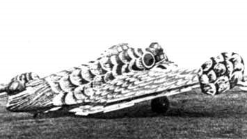
The Kalinin K-12 was conceived as a tailless aircraft in a flying wing configuration with wingtip empennages of mixed construction.
The oval section fuselage featured three sections that were bolted together. The structure was conceived of welded steel tubes covered in fabric. The navigator and gunner positions in the tail featured steel and duralumin cladding.
The midplane featured two spars made of chrome-molybdenum alloy steel tubes. The wing nerves were made of 10 х 8.5 mm steel tubes. The forward region of the midplane, between the leading edge and the spar and the rear, from the spar to the trailing edge, were constructed of duralumin and stainless steel. The central area, near the engines and the fuselage, were covered with fabric.
The wing consoles, with R-11 profile and trapezoidal shape, also had a double spar structure made of wood. The covering was plywood. The vertical and horizontal tail surfaces were made of fabric-coated steel tubes. The three-section ailerons were located along the entire length of the wingspan. The central section was used as elevons.
The power nacelles occupied the entire wing chord on the intrados and served as shelter for the main landers. The main landers on the prototype were fixed and used low-pressure wheels to allow them to operate over unprepared runways. These landers lacked depreciation. In winter operations the train had to be replaced by one of skis with hydraulic amortization.
The K-12 was powered by two M-22 engines produced at Factory No.19 with 2.8 meter diameter metal propellers. The starting of the engines was carried out by means of compressed air or with an external starting system. The use of Townend rings allowed proper cooling of the engines. During the tests, no abnormal heating was observed in the cylinder heads. The use of this hood, which could be easily removed, made it possible to facilitate technical intervention actions.
The fuel system consisted of 4 tanks located symmetrically in the wing, with a total capacity of 900 kg. The oil capacity was 90 kg.
The Kalinin K-12 was designed for a crew of three. The pilot was located in the high cabin located in the central area of the fuselage. In the nose was the gunner navigator with a turret armed with machine guns. The navigator’s cabin had double control and at least conceptually it should allow flight operation, despite the fact that in practice the instrumentation there was very poor. At the end of the tail section was located a defensive turret operated by the gunner. The cockpit and fuel tanks could be covered with removable armor.
Kalinin K-12 cockpit
The aircraft in its bomber configuration was capable of carrying 500 kg of bombs inside the fuselage. Defensive armament consisted of two 7.62mm ShKAS machine guns operated by the navigator and tail gunner.
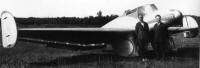
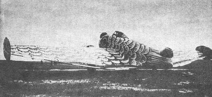
In order to check the theoretical calculations, Kalinin decided to build, in addition to the scale models for the aerodynamic tests, a 1:2 scale glider of the VS-2. This 9 meter wingspan glider was built in Kharkiv in 1934 and air tested by pilot VO Borisov.
Construction of the scale glider
The first flight presented problems. After the glider broke free from the tug the pilot was unable to control the model and the glider inverted. The pilot launched (or was launched) from the glider, which once lightened, hovered smoothly and landed on the back. After the repairs, the causes of the problem were established and a new test was carried out, which this time passed without problems. The pilot VO Borisov successfully carried out about 100 flights, aimed at checking the real behavior in different flight regimes.
The builder AV Kovalienko next to the scale glider built in 1934
The transfer the new location in Voronezh also added to development delays. Only at the beginning of 1936 was the construction workshop able to begin work on the full-size aircraft.
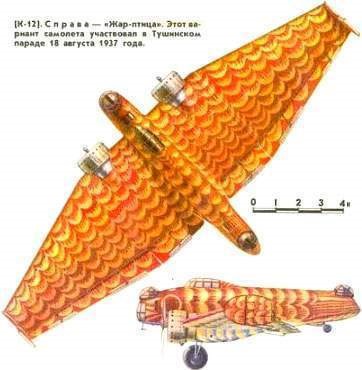
In June 1936 the K-12 plane left the workshops for the factory test airfield and a month later the test pilot VO Borisov made the first flight. The factory tests requested were carried out without difficulties. This aircraft in the colors of the “Fire Bird” (Zhar Ptitsa) took part in the festivities for the day of the Soviet Air Forces on August 18, 1937 over Tushino. At that time, the state tests began at the NII VVS.
Kalinin K-12 during state testing
Third rank military engineer Samarin was selected as the person responsible for the tests. Borisov was chosen as the pilot by the factory. The engineer Nersisyan, the captain Shaurov and the technician Androsov also participated. The main objective of the tests was to define the flight properties of the VS-2 2M-22 aircraft and its performance, as well as to study the characteristics of the flying wing system in relation to its stability and flight control.
At the end of 1936 the aircraft was flown by PM Stefanovski , who issued a completely negative assessment of the model. The particular characteristics of the configuration brought as a consequence that the pilots during the tests were conducted with suspicion and it was considered that the VS-2 was a dangerous device. This played a not insignificant role in the future of the model.
The VS-2 2M-22 accumulated 62 flights with a total of 33 flight hours, including 12 hours in 16 flights made at the NII VVS. In them it was shown that the model was stable in flight and responded favorably to the controls. Stability problems were noted during single-engine flights and during takeoff and landing operations due to ineffective wingtip empennages. Big problems were observed due to the lack of retracting of the landing gear. The tests could not be fully developed.
Problems prevented flights with overloads, combat manoeuvres, weapons tests, dynamic stability, and manoeuvrability.
In the conclusions it was noted that the VS-2 2M-22 aircraft with a flying wing scheme was considered purely experimental. For this reason, the objective of the tests had been directed to the definition of its stability and control properties of tailless aircraft, which at that time were considered the main questions in relation to this configuration.
The data obtained in the flights were not considered sufficient to be able to answer the questions, but they did give the possibility of obtaining some fundamental conclusions for the future development of aircraft in this configuration.
The VS-2 2M-22 aircraft showed good flight conditions. Horizontal flight could be maintained at speeds of 120 – 200 km/h and in this range stability was acceptable. The plane could glide at speeds between 115 and 120 km/h. It took off easily after a not very long run and at a fairly low speed, over 100 km/h. The takeoff trajectory had a tendency to be carried out in a circle. The landing speed was also low, close to 77 km/h. The airplane was considered statically stable under conditions of center of gravity location at 27% of length with rudders locked. With free rudders the plane was not stable.
The effectiveness of the vertical wingtip planes was considered poor, particularly in take off and landing operations and single-engine operations. It was proposed to eliminate these surfaces and replace them with a conventional empennage.
The effectiveness of the ailerons on landing was diminished due to their use as elevators, which was considered unnecessary. It was proposed to work on increasing the effectiveness of these surfaces.
The absence of suspension on the landers made landing difficult. The plane tended to jump after touchdown. Sometimes these jumps were so great that the pilot was forced to give up the throttle again and go up to make a new turn over the aerodrome. It was recommended to add oleo-pneumatic amortization systems. In the same way, it was decided to modify the tail skid to provide it with orientation in order to improve the operation on land.
Flying the plane from the navigator’s cockpit was impossible due to the lack of completeness of the navigation equipment.
The maximum speed obtained of 219 km/h was lower than that of the planes of the time. This was explained by the poor aerodynamic quality of the structure, which had many exposed surfaces and the already obsolete M-22 engines. The advantages of the tailless configuration were affected by the large size of the fuselage.
The defensive capability of the VS-2 was generally superior to that of any tailed aircraft. This model was characterized by the simplicity of the solution to the problem of defense of the rear and upper hemispheres. Despite this, the VS-2’s armament left a lot to be desired. The firing points did not guarantee the total defense of the aircraft and the defense of the aircraft against attacks from below was not guaranteed in any way. The protection of the firing positions was considered deficient.
The cockpit was valued very well. Visibility during the flight and take off was quite good. In the cabin in summer it was quite hot, even after lowering the glass on the left. The teams on the blackboard had a good distribution, with the exception of the variometer, which was very low and it was difficult to see the status.
The overall assessment of the aircraft in the NII VVS report signed by Filin and Markov highlighted that the VS-2 2M-22 (K-12) aircraft was of great interest as an experiment in creating a flying wing configuration aircraft in a military configuration. It was considered that this scheme presented advantages in relation to the conventional system in terms of visibility, cleanliness for defence and take-off and landing operations at low speeds.
However, in the version presented, the VS-2 had very poor performance and poor weapons, so it was impossible to consider it a modern military aircraft. The model was considered experimental.
It was recommended to return the plane to its builders in order to improve all the problems. It was proposed to GUAP make these changes and begin factory tests for March 1, 1938. Then submit it for carrying out the full program of state tests.
On December 8, 1937, V. Smushkievich signed the NII VVS report and requested to insert into the experimental construction plan for 1938 the development of an experimental aircraft on the VS-2 scheme with technical requirements and armament in correspondence with a modern military aircraft. The possibility of serial production will be evaluated only after the completion of the state tests.
For two months the plane was overhauled, installing more powerful M-25 engines with variable-pitch metal propellers and electrically-operated retractable landing gear. The weapons were also modified. With these modifications the maximum speed increased to 420 km/h. After finishing the factory tests, the improved aircraft was delivered in April 1938 to the evaluation commission, which approved its serial production.
The K-12 “Zhar Ptitsa” demonstrated at the Tushino air parade was the only aircraft built. On April 1, 1938 K. A. Kalinin was arrested. According to the opinion of the Military Collegium of the Supreme Court of the USSR, he was accused of being an “enemy of the people” and shot. It has been speculated that the builder could have sold information to John Northrop about his studies on the subject of flying wings and also that he had relations with German espionage, but none of these theories have been proven.
The leadership of the aviation industry decided to cancel all the works of this builder, including the destruction of 10 copies that had started production at the Voronezh factory and were at different stages of completion. The lone K-12 was also destroyed after removing all useful equipment and constructive elements. An important part of the project documentation disappeared.
Kalinin K-12 Powerplant: 2 × Shvietsov М-22 480 hp Wingspan: 20.90 m Wing area: 72.70 m² Length: 10.30m Height: 3.65m Empty weight: 3070 – 3210 kg Normal take off weight: 4200 kg Wing loading: 57.8 kg/m² Power load: 4.38 kg/hp Fuel capacity: 900 kg Oil capacity: 90 kg Speed at sea level: 211 km/h Maximum speed at 3000 m: 228 km/h Cruising speed: 189 km/h Practical range: 1100 km Practical ceiling: 7170 m Landing run: 700 m Take-off run: 700 m Armament: two 7.62 mm ShKAS machine guns Bomb load: 500 kg. Accommodation: 3