Martin-Baker MB.3

With the Spitfire and Hurricane in widespread service, the Air Ministry contemplated their eventual replacement. Specification F18/39 issued on May 1, 1939, called for a single seat interceptor armed with two cannon or eight machine guns, capable of 400mph (644km/h) at 12,000ft (3,658m) at an all up weight of 15,000 lb (6,800kg), and with a ceiling of 35,000ft (10,668m).

In the summer Martin Baker received an order for three prototypes of Martin’s new MB.3 at a total contract price of £64,000. With war imminent Martin had been asked to ‘come aboard’ and produce prototypes to contract as had established contractors in the earlier F5/34 submission.

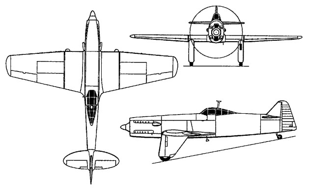
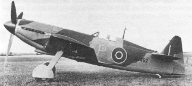
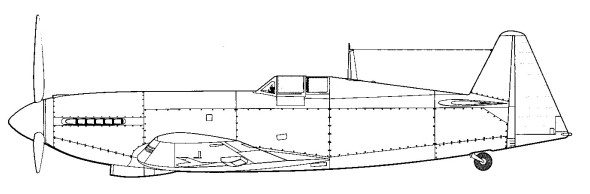
In its fuselage structure the MB.3 was an advance on its predecessors. The skinning was of stressed light alloy and flush ¬riveted except where the numerous inspection panels were situated. The wing was completely new, its basis being a D section torsion box. A substantial light alloy spar web was adopted, with upper and lower spar booms made from laminated high tensile steel strip, the number of laminations decreasing towards the tip. The structure was covered with heavy gauge flush riveted light alloy stressed skin. The fin was reminiscent of that fitted late in the life of the MB.2. All control surfaces were fitted with torsion bar spring tabs to enhance manoeuvrability.

Martin had intended a Rolls Royce Griffon as the powerplant, this being the engine specified in F18/39. As an interim measure, the company was supplied with a Merlin ballasted to simulate the Griffon. With the advent of the Napier Sabre, which promised to give over 2,000hp (1,492kW), a second option became available and in 1941 Martin Baker was awarded a revised contract for a Napier Sabre II version of the MB.3. The Sabre drove a de Havilland three bladed constant speed propeller. Shallow ducted radiators were incorporated under the left wing (oil cooler) with the main radiator under the right wing.

The main inward retracting undercarriage of the MB.3 had an track of 15ft 5ins (4.7m). The wheels were raked so far ahead that the threat of a nose over was minimal. Undercarriage operation was by 60 lb/sq.in (27kg/2.5csq.m) pneumatic system. A second, lower pressure pneumatic system was used to operate the large split flaps which had no intermediate settings.

The intended armament consisted of six 20mm Hispano cannon, to have 200 rounds per gun. The armament was removed prior to flight trials and never tested.

The prototype MB.3, R2492, emerged from Denham in the summer of 1942, the contract completion date having been set for the previous March. Initial taxiing trials were undertaken at Denham and demonstrated a very stable ride.
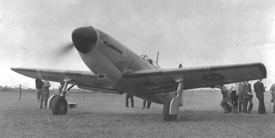
Martin received orders from the Ministry of Aircraft Production (MAP) to use RAF Wing in Buckinghamshire for flight testing and during August 1942 the MB.3 arrived at Wing in crates, Val Baker flying it for the first time on 31 August 1942. According to an eye witness, the MB.3 with its 24 cylinder sleeve valved Napier Sabre flew well for a short period but then had to make a hurried landing because of the threat of engine overheating due to inadequate radiator cooling.

In subsequent flights in early September, Baker found the MB.3 highly manoeuvrable. On September 12, 1942, Valentine Baker took off satisfactorily, but shortly afterwards the Sabre failed when a sleeve drive crank broke, resulting in immediate and total loss of power. Baker attempted a dead stick landing but after touching down in a small field, the MB.3 hit a tree stump and was destroyed; Baker was fatally injured.

After the loss of R2492, the MB.3 prototype programme came to a halt. Martin decided to start again with a new design. It had been by no means certain that the MB.3 would have secured a production contract.

Engine: One 2,020hp (1,506kW) Napier Sabre II 24 Cylinder H-¬type piston
Max speed 430 mph (691km/h)
Range 840 miles (1,351 km)
Initial climb, 4,350 ft/mm (22,09 m/sec)
Operational ceiling 34,500ft (10,515m)
Empty weight 8,500 lb (3,855kg)
All up weight 11,000 lb (4,989kg)
Wnigspan 35ft 2in (10.7m)
Wing area, 262.64 sq ft (24,40 sq.m)
Length 34ft 1 in (103m)
Height: 14ft 3in (4.3m)
Armament: Six Hispano cannon intended.
Martin-Baker MB.2

In 1935, with a company employing 35 people, Air Ministry Specification F5/34 called for a single seat monoplane interceptor armed with six or eight machine guns. A retractable undercarriage was required and an enclosed cockpit; a speed of at least 275mph (442kph) at 15,000ft (4,572m) was stipulated.

This requirement was taken up by Bristol (Type 146 835hp/622kW Bristol Perseus), Vickers (Venom 625hp/466kW Bristol Aquila), and Gloster (G.38 840hp/626kW Bristol Mercury IX). James Martin submitted the MB.2.

Funded as a private venture, Napier lent an air cooled Dagger M.3 24 cylinder upright ‘H’ type engine with a rated output of 798hp at 5,500 ft / 1675m. The Dagger was not yet fully developed and suffered from lack of power yet the particular engine (No 77101) eventually installed in the MB.2 seems never to have given any trouble. Cooling air was exhausted through a controlled outlet on the fuselage underside.

Other equipment to support the MB.2 included a fixed pitch, two bladed wooden airscrew from the Airscrew Company and Jicwood Ltd and a set of eight Browning 0.303 in machine guns, taken from the first batch manufactured under licence in Britain, in 1937. The build phase for the MB.2 began in March 1936, the month of the first flight by the prototype Spitfire.

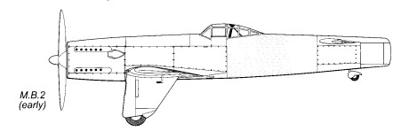
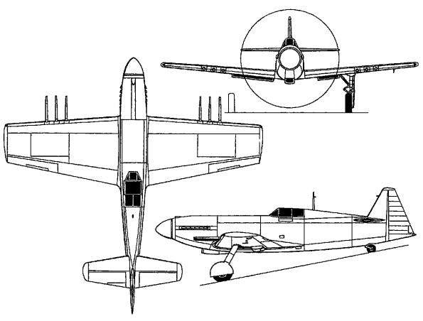
Conceived for manufacture in large numbers by semi¬skilled workers at low cost, the M.B.2 employed a steel-tube structure with fabric skinning, and carried an armament of eight 0.303-in (7,7-mm) Browning guns in the wings. The depth of the fuselage was virtually constant from nose to tail and vertical tail surfaces were eliminated, the rudder being hinged to the sternpost behind the elevators.

The MB.2’s airframe employed the previous steel tube process, but stronger, and metal skinning was used more widely. The enclosed cockpit was placed well back and given a raised canopy with glazing fore and aft.

The canopy was hinged to starboard but could not be jettisoned. The rear glazed area of the hood enclosed an electrically operated extendible crash post which was automatically actuated when the flaps were lowered. The fuselage lines were square cut, the depth being almost constant from engine to sternpost. A tubular cradle supported the engine which had stub exhaust ports. The metal covered areas of the fuselage, forward of the aft cockpit area, were equipped with quick release inspection panels held with Dzus fasteners.

The wingspan was shorter than the fuselage length, but designed to enhance stability and control in yaw. The wing was constructed as a centre section and two outer panels. A small amount of dihedral was employed and the wing tapered slightly along the leading edge but more acutely along the trailing edge. Blunt tips were provided, together with inset ailerons. The wing carried the eight machine guns in two clusters of four, outboard of the undercarriage.

Martin elected to employ the rear fuselage as the fin, with the rudder hinged to the sternpost, the design lacking any conventional fin at all, in order to reduce weight and drag. With balancing of the fuselage keel area, the tailplane was high mounted so that the rudder could operate effectively.

To save development time the undercarriage was fixed, with trouser fairings. To reduce drag further, Martin fitted the oil cooler in the leading edge of the port fairing. A 60 lb/sq.in pneumatic system operated the split flaps and the wheel brakes. There was no hydraulic system.

The aircraft was generously provided with inspection and maintenance access points. The engine complete could be removed and replaced in less than 90 minutes. The complete outer wing assembly could be removed in 25 minutes. The machine guns, together with their ammunition tanks, were locked in position with pins, removal via a very large access panel taking just five minutes.

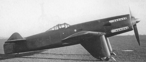
The private venture MB.2 prototype was completed in July 1938, the Air Ministry making RAF Harwell available for flight tests. The MB.2 arrived late in the month, painted in a strange “air force green” livery overall, and sporting the totally unofficial identity ‘M B 1’.

Val Baker first flew this prototype on August 2, 1938, a few days after the sixth production Spitfire had been delivered to the RAF. He found that directional stability was poor. The aircraft was quickly fitted with a vestigial fin, and also at that time, allotted the civil registration G AEZD. Even with the addition of the miniature fin, Baker found the handling unsatisfactory, though he achieved a level speed of 320mph (515km/h) at a weight of 5,530 lb (2,500kg), which included guns and ammunition.

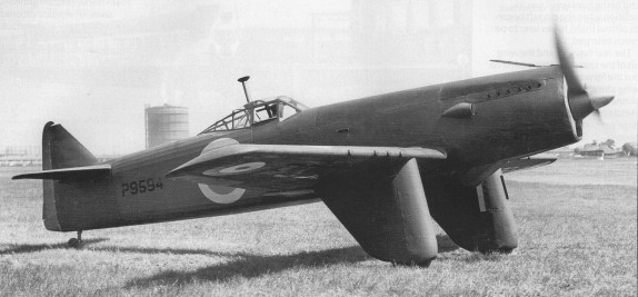
After initial company tests, the Air Ministry accepted the MB.2 for evaluation purposes, the aircraft being repainted overall deep olive green and allotted the service serial P9594. It arrived at A&AEE, then still at Martlesham Heath, during November 1938. James Martin went with the aircraft and explained to those concerned his thinking behind the configuration.

In the official A&AEE report, which was issued the following month, the MB.2 received high praise as a piece of engineering. As a flying machine it was unpopular. The ease of maintenance and accessibility drew considerable acclaim. The cockpit area attracted mixed comments. It was praised as warm and comfortable, roomy and draught free, but the unjettisonable canopy was criticised. The wind down side windows were popular but an openable direct vision panel ahead was needed. The cockpit was assessed as difficult to enter and an extra step was suggested. However, the excellent view from the cockpit drew favourable comment, as did the crash pylon.

Flap actuation also attracted criticism; the flaps were operated by a simple lever which provided full flap for landing, without an intermediate setting, and only a meagre warning light showed when they were down. The A&AEE suggested a more positive flap position indicator, and also different trimming facilities. Armament arrangements were praised; the guns were made accessible through quick release hatches and working platforms were formed into the wing upper surfaces.

The handling of the MB.2 was unacceptable to the testing authorities. The elevators were over sensitive, particularly with power off; lower gearing was suggested. Ailerons left much to be desired, being ineffective at low speeds and heavy at high speeds. The rudder layout was found to be particularly poor and produced considerable yaw even with small movements. At high power, even full left rudder could not prevent a gentle turn in the opposite direction. Stability in all three planes was thus found wanting, and consequently the MB.2 made a poor gun platform. Finally it was an uncomfortable ride for the pilot.

After the tests at Martlesham P9594 returned to Denham, where the fin and rudder were modified once more, taking on a larger and more conventional appearance. A study was also carried out to enlarge the tailplane, in order to improve pitch behaviour and encourage gliding properties. The modifications appear to have rectified the stability and control problems, for Val Baker was able in May 1939 to give an inspired demonstration at Heston, which included steep, low level turns and a dive at some 400mph (644km/h). It seems that the length of the Dagger, which might have reduced power of manoeuvre except in roll, was offset by the comparatively short wing span.
The Air Ministry purchased the only MB.2 built in July 1939 intending to use it as a test bed, the aircraft eventually returning to Denham where it was dismantled in 1941.

Engine: One 798hp (595kW) Napier Dagger M.3 24 cylinder H-¬type piston
Max speed 320mph (514km/h)
Normal range 300 miles (482km)
Operational ceiling 31,000ft (9448m)
Empty weight 3,840 lb (1,741kg)
All up weight 5,400 lb (2,449kg)
Wingspan 34ft (10.3m)
Length 34ft 6in (10.3m)
Height 12ft 3in (3.3m)
Wing area 235sq.ft (21.8sq.m)
Armament: Eight 0.303 in Browning machine guns.

Martin-Baker MB.2

Martin-Baker MB.1

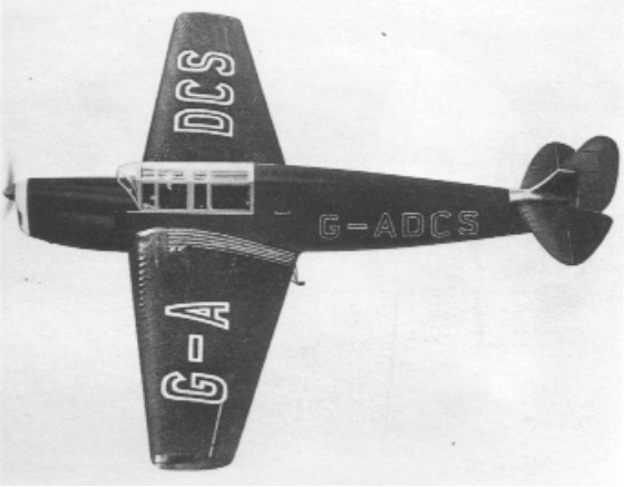
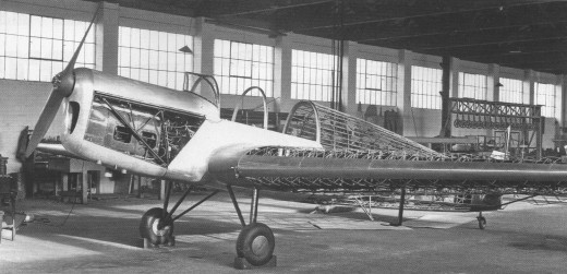
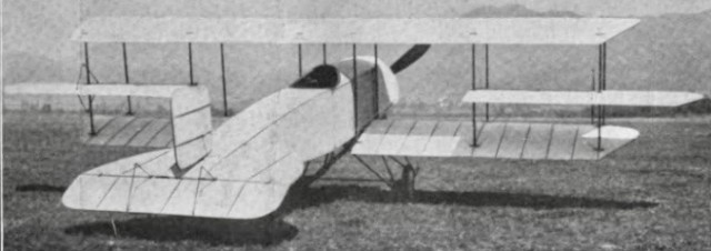
The M.B.1 was built primarily to demonstrate Martin’s original patented system of lattice-girder construction patented by James Martin in 1931. Designed during the late summer of 1934 and was a two seat low wing cabin monoplane.

The entire primary structure was built from thin gauge high tensile steel tube, cut to a precise length with a hacksaw. The tube ends were secured to each other either by brazing or (more frequently) by flattening, brazing and drilling the ends, then fastening with a bolt to a castle nut brazed inside a small cylindrical insert fixed in the adjacent tube. The advantages of this type of metal structure were simplicity and lightness of construction, versatility, and the benefit that unskilled labour could be utilised during manufacture. Martin was especially concerned that his new aircraft, known simply as the MB.1, should be straightforward to construct and maintain. Because very little light alloy was used in the manufacture, delay and cost through heat treatment and anti corrosion processes was avoided to a great extent. All the elements for the tubular structure, inserts, saddle¬-washers and castle nuts, were produced in house.

The low set monoplane wing of the MB.1 wing spar was based on three span wise thin gauge steel tube booms, two forming the aft surface, one mounted almost vertically above the other, and the third forming the leading edge. These booms became thinner, and tapered towards each other towards the wingtip. The wide base of this pyramidal spar, together with the large diameter of its component booms, provided considerable strength, especially in torsion. Inserts and bolts secured linking tubes which were used to add to the spar strength. Wing ribs constructed from brazed small diameter T.5 tube were then bolted to the spar, as were the wing stringers. Welded aluminium fuel tanks of long, thin triangular section were mounted inside the spars. The wings of the MB.1 were designed to fold, to minimise storage space, the folding procedure being a one man operation. The same method of manufacture was also used on the tail surfaces.

The rear section of the fuselage was also of bolted tube. Machined, flanged steel sleeves, attached to the longerons at focal points, provided stringers, the area being faired by light metal hoops of near oval shape. The mid and forward fuselage construction was principally of brazed tube. Evidence of Martin’s attention to systems detail was provided by the cock assemblies, for fuel supply, pump isolation and other functions which were loaded with a spring ball giving ‘feel’ when they were actuated.

The MB.1 was powered by a 160hp (119kW) Napier Javelin IIIA six ¬cylinder inverted in line engine, with electric starting, lent to Martin Baker by Napier. A fixed pitch two bladed wooden airscrew was fitted, the engine installed in a brazed tubular mounting. The practical nature of the MB.1 was particularly evident around the nose where the doping pump had connections to both the carburettor and the induction pipe, the inlet manifold being lagged and warmed, the fuel and oil filters being easily accessible.

The cowling side panels could be supported from their hinges in a horizontal position to form shields should maintenance be necessary while the engine was running.

The MB.1 was entirely fabric covered apart from the fin and the wing walkways which wore Duralurnin skins. Undercarriage arrangements were very simple and again employed tubular construction with uncomplicated shock absorber struts and low pressure tyres.

MB.1

By the end of March 1935 the aircraft was completed and it was taken by road to Northolt. It was eventually given the civil registration G-ADCS, and Capt Baker took the aircraft for its first flight in April 1935, painted black overall. He found that it possessed good flying qualities and had a maximum speed of 125 mph. The company recorded that ‘DCS had “sound inherent flying qualities”.

With severe cash flow problems, only one MB.1 was built, flying for only a few hours before being placed in storage at Denham after work began on the M.B.2, but in August 1939 the M.B.1 was inspected (and rejected) byAir Ministry representatives for possible impressment into national service.

It is 99 per cent certain that it was burnt in an April 1940 fire at Denham, which destroyed the existing factory. It was definitely not lost in a fire in March 1938.

Engine: One 160hp (119kW) Napier Javelin IIIA six cylinder in¬line piston
Max cruising speed 140mph (225kph)
Stalling speed 50 mph (80kph)
Endurance 3 hrs 30 mins
Empty weight 1,5601b (707kg)
All up weight 2,3501b (1,065kg)
Wing span 37ft (11.2m)
Length 28ft 10in (8.7m)
Height 9ft 9in (2.9m)
Wing area 206sq.ft (19.1sq.m)

Martin Aircraft JetPack

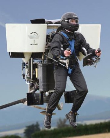
Oshkosh, Wisconsin, 2008, was the launch pad for a world first in personal flight today when Martin Aircraft Company unveiled the ultimate personal flying machine – the Martin Jetpack. Glenn Martin, Inventor of the Martin Jetpack and Managing Director of Martin Aircraft Company, showed the world that sustainable personal flight is now possible.

Glenn has devoted almost 30 years to the research and development of the Martin Jetpack. Glenn and a group of avionic, technical, design and production experts at Martin Aircraft Company have created a jetpack that flies 100 times longer than its predecessor the Bell Rocket Belt.

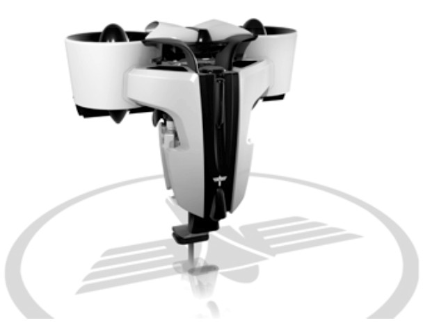
The Martin Jetpack has a patented fan jet technology, uses regular gasoline, complies with Ultralight regulations and is easy to fly after completion of a unique training program.

In 2005, Prototype 9 achieved sustained flight times, laying the foundation for a viable and successful pre-production prototype to be developed. In 2008 the Martin Jetpack was launched.

The core of this machine is the fan, its duct and the flow straighteners. These have cost the team countless hours as they pushed the boundaries of the science of ducted fans in a low speed environment. Mr Martin found that while many of the ‘facts’ older designs were based on were as solid as the day they were first committed to the text book, others were due either to the originators trying to simplify the calculations because of a lack of modem processing power, or had a fudge factor to cover steps in the process that didn’t become clear until high quality CFD systems were available.

A long series of experiments with Solidworks 3D CAD-drawn concepts run through CFD (a computer based simulation of a wind tunnel) brought about a series of promising steps forward in efficiency that were checked out on the workshop test rig. The team now have a fan blade that is not only light at roughly 100gm per blade, it also runs at 92 percent efficiency. The best Mr Martin can find elsewhere is the lift fans on the JSF which are published at 87 percent. The team have also worked hard to get the whole ducted fan package efficient across a broad speed range. The 2011 setup has a relatively flat efficiency curve with a small peak at around 60 km/h forward speed. Each fan unit is considered to be torque neutral which means the airflow from the duct is so close to straight that the twist is almost immeasurable, giving gains in thrust.

The fans needed a light, unobtrusive and reliable drive method which led the team to the modem synchronous belt. The latest designs have carbon fibre tensile cord inside the polyurethane belt with nylon facing on the teeth. The power transfer for width is better than for chain and challenges many gear-driven alternatives especially on weight. The major requirement for belts is to keep an alignment of better than half a degree and constant tension. Most belt drives use aluminium housings which shrink and grow with ambient temperatures let alone engine temperatures, so the decision was taken to go to a carbon fibre structure to all but eliminate temperature related dimension changes. The carbon structure also greatly assisted in keeping the alignment within spec.. The final touch was to make sure the drive and driven pulleys were fully supported by bearings on either side: no poor quality over hung shafts would be allowed in this design.

Once the horsepower requirements of the fans were known, a search of all known production engines was made. Power density, brake specific fuel consumption, package size and reliability were recorded, then checked against the requirements. No production engine had the power to weightt ratio needed allied with the high reliability the team demanded. Martin Aircraft sought advice from various companies and found that marine applications, such as outboards, shared many of the operational needs of the aviation world. Both users tend to run at three settings: idle; around 75% continuous; and 100% for extended periods. With this in mind, questions were asked of one specialist, Mercury Marine, to ascertain the level of stress an engine could be placed under and still achieve high reliability. The end result was four gentlemen For reliability and packaging reasons a water cooled V4 two-stroke was chosen. This gives a power pulse every 90 degrees which brings the peak and mean torque at the crankshaft nice and close together, resulting in a smooth output to the fans. To further smooth the power delivery, there is a ‘centre flex’ type rubber coupling before the drive enters the c!rive pulley. The cylinders are from Honda (CR 500 motor crosser), modified by replacing the steel sleeves with aluminium coated with nikasil. The change gives better heat transfer and reduces the engine weight by over 3kg. New heads have been made which have a carbon fibre top cover to keep the water in and the weight down.

The exhaust system is a simple yet brilliant piece of work which through its various interconnections and pipe lengths gives a lesser improvement at peak rpm compared to a full expansion chamber system, but functions well over a very wide band. The torque curve is one of the flattest I’ve seen, which means the horsepower line has no real humps or hollows as the rpm rise. Reliability is vital in a machine that has no wings (just a BRS ‘chute fitted) so the engine team have incorporated all the hallmarks of a reliable engine such as mean piston speeds below 15m/s, bore and stroke ratio kept below 1.15 / 1, and porting size and shape designed to protect the rings as they pass. All based on hard-won data from the marine industry where after tens of thousands of engines they have learnt a thing or two.

The cooling system has a neat (and patented) method of pumping air through the radiator. To understand it, think about blowing air across the top of a milk bottle. The airflow from your breath across the top creates a draw on the air in the milk bottle. The horizontally mounted radiator on thej etpack has ducts that sit on the side of the entry to the ducted fans so that the rush of air going into the fans pulls air through the radiator. The more horsepower applied the more airflow through the fans and therefore more flow through the cooling system. Another simple yet brilliant design.

The first prototype Jetpacks were manually controlled and apparently not hard to fly, but the team have their eye on a market where a high level of automation seems preferable. The fully fly-by-wire system uses the same unit as the Predator UAV for its air speed, gyro, magnometer, GPS and other critical inputs, but the processing and control is done by a dual redundant Martin Aircraft system. When creating it the team were helped immensely by a professor from Bremen University who joined for six months to apply his experience in control systems. He also helped with the creation of a proper flight simulator suitable for training and checking out software changes to the real thing. The fly-by-wire approach allows the operator to simply command the machine to rise or fall, turn left or right, leaving the control units to move the duct vanes and the cruciform, surfaces in the jetstrearn to create directional change while changing the engine output to control height and speed.

Release the controls at any time and the system will maintain height and gradually bring you back to stable hover.

Martin Aircraft has created a concept, not just a one-off machine. The current version suits US Part 103 rules, so it is limited in overall weight, speed and fuel capacity. Accepting these limitations opens up a large private market for the Jetpack. A slightly bigger ‘unregulated ‘ version on the same basic configuration can lift 200kg-plus payloads versus the current 115 kg and stay aloft for over 90 minutes. Still bigger versions exist on paper.

The 12th prototype featured a 200 hp V-4 engine driving two ducted fans. It had been flown to more than 3000 ft and 74 kph. The planned price at that stage was US$150,000 to US$250,000.

Standard Equipment:
Flight and Engine displays
Harness
Ballistic Parachute
Retractable undercarriage
Energy absorbing undercarriage.

Gallery

Height: 5 ft
Width: 5.5 ft
Length: 5 ft
Structure: Carbon fibre composite
Empty weight: 250 lbs (excluding safety equipment)
Gross weight: 535 lbs
Useful (Pilot) Load: 280 lbs+
Maximum thrust: 600 lbs+
Fuel Capacity: 5 US gallons (as required by FAA Part 103,Ultralight Regulations)
Fuel burn: 10.0 gph
Engine: Martin Aircraft 2.0 L V4 2 stroke, rated at 200 hp (150 kw). Max 6000 rpm.
Electrical system: 12 V DC Battery, starter, 360 w alternator.
Rotor: Carbon / Kevlar composite diameter 1.7 ft
Max: 7058 rpm
Range: 31.5 miles (at max speed of 63 mph as required by FAA part 103).
Hover in ground effect: 8000 ft (estimated)
Hover above ground effect: 8000 ft (estimated)

Martin Aircraft Co

In 1998 the Martin Aircraft company was founded with the specific goal to research and develop a jetpack that could fly 100 times longer than the Bell Rocket Belt (26 seconds). In 2005, Prototype 9 achieved sustained flight times, laying the foundation for a viable and successful pre-production prototype to be developed.

The founder of Martin Aircraft Company and the inventor of the Martin Jetpack is Glenn Martin. Richard Lauder is the company’s Chief Executive.

Glenn Martin

Based in Christchurch, New Zealand, Martin Aircraft Company is developing the world’s first practical jetpack, the Martin Jetpack. Launched to global acclaim at the 2008 Experimental Aviation Association AirVenture air show in the USA, Martin Aircraft Company planned to fulfil its first customer orders in 2010.

Martin 162A Tadpole Clipper

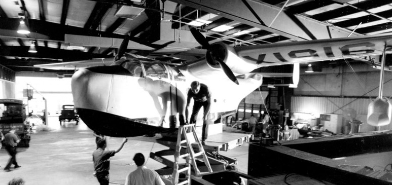
A piloted, three-eighths scale model of PBM flying boat; single-seat test aircraft built to generate aerodynamic data to design and build full-scale Martin PBM flying boat.

The construction was fabric-covered spruce plywood and aluminum.

In 1987, a dedicated and enthusiastic team of volunteers, many of whom were former Martin employees, began an exhaustive restoration of the 162A. After more than 10,000 man-hours of labor, the 162 was ready for display while on loan to the Museum of Industry in Baltimore, not far from where the “Tadpole Clipper” had been built and flown. Portions of the rear fuselage under-surface were left uncovered to illustrate some of the modifications made in the 162A’s hull during the course of its testing.

Wingspan: 43ft 5 5/8in / 13.25m
Length: 28ft 6 1/8in / 8.69m
Height: 12ft 1/8in / 3.66m
Weight: 2819.7 lb / 1279 kg