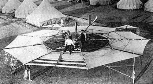
McCormick – Romme Umbrella Plane

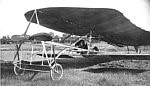
Harold F. McCormick, of the harvesting machine manufacturing business, and millionaire, John D. Rockfeller, Jr. decided, about September 1910, to support the aircraft design ideas of, a New York inventor, William S. Romme. In 1910 Romme had won a design contests first prize, for length of flight, stability and originality, with an unusual circular-shaped model monoplane. It was this model that Romme hoped to develop into a full-scale airplane and override the Wright patents on the airplane. McCormick and Rockfeller formed a corporation to exploit the Romme designs.

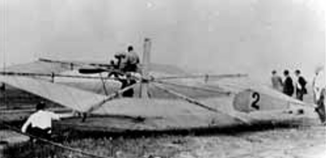
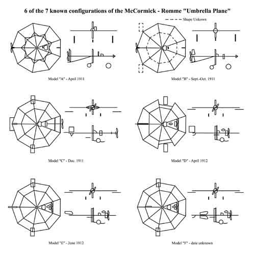
Because of shortcomings of the Wright machine, and the patents controlled by the Wright Brothers forced other designers to use radically different designs. One of these pioneer machines was the McCormick – Romme Cycloplane of 1911 with its spoked-wheel platform, stalky undercarriage, unprotected pilot at the center, and the propeller driven by long shaft from the centrally mounted engine. Like most early airplanes of these times, constant changes were made to correct problems. At least seven different configurations of the Cycloplane are known.
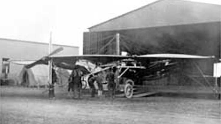
With McCormick’s financial backing work continued at Mineola, Long Island. The first monoplane was wrecked by wind in November 1910. Plans were immediately made to rebuild the plane in the south. In April 1911 a monoplane built in Belmont, New York and given some preliminary testing was now in San Antonio, Texas. While running the plane over the ground, it struck a rut, was turned over by the wind and badly damaged. Romme escaped without injury. Besides the McCormick – Romme contingent other civilians using the San Antonio flying area near Fort Sam Houston were the Max Lillie flying school from Chicago. Lillie’s mechanic and the McCormick – Romme group with the help of some soldiers, set the plane on a two-wheeled cart and returned it to its hangar. After this fiasco, little further progress seems to have been made, probably because of the wait for the Gnome engine. Meanwhile the Aero Club of Illinois completed a new 180-acre flying field at Cicero, just west of Chicago. The completion of this field and its facilities were all that was necessary for McCormick to move his experimental work to Chicago. It was here that the McCormick – Romme machine was referred to as the “Umbrella Airplane” in the Aero Magazine. While the monoplane had been reported as McCormick’s design, he recognized the need for skilled engineers and mechanics to convert his and Romme’s ideas into a practical airplane. He hired a young graduate of the Armour Institute, Sidney V. James. While he participated to some degree in all of the McCormick projects, he concentrated on the Mustard Plaster airplane concept, and specialized in propeller design and wrote extensively on the subject.
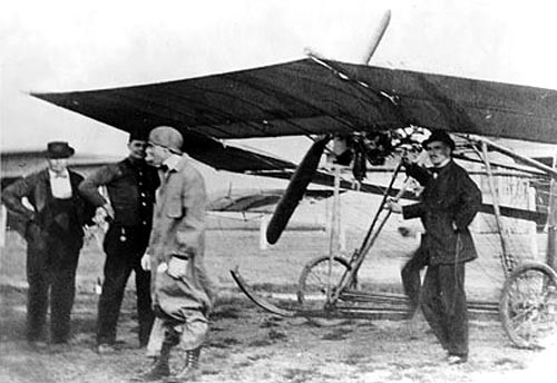
At the same time McCormick hired another engineer, fresh from the University of Pennsylvania, Chance Milton Vought. He guided the development of the Umbrella Plane through most of its entire career.

When the Cicero Flying field was officially opened on July 4, 1911, besides the McCormick monoplane (The Mustard Plaster) and the McCormick – Romme Umbrella Plane, eleven other airplanes were located here. By July 15, 1911, the two McCormick airplanes had their 50H.P. Gnome engines installed. On August 23,1911, Romme made the first successful flight in the Umbrella Plane, reaching a height of 15 feet. Between the Texas accident and the July flight the Umbrella Plane was rebuilt. While the appearance was not significantly changed the modifications were very important, control wise. Movable control surfaces were installed on each side at the rear of the circular wing, rudders with greater cord replaced the two tall narrow rudders, and the triangular center projections on the wing were removed. The pilot now sat with his back against the center post and his feet straddling the cylindrical cowling surrounding the Gnome engine.
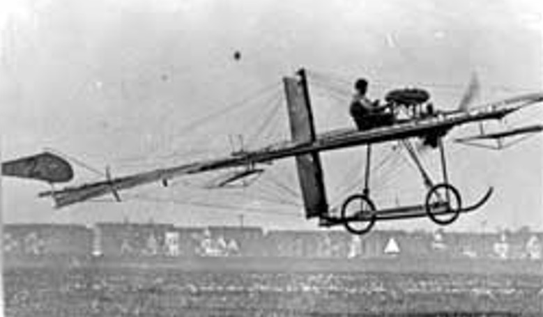
Experimentation continued until the fall of 1911, sometimes successfully. Problems continued with the Umbrella Plane. Exactly what Chance Vought’s contribution was, is hard to define but he was the principal engineering talent behind the work, with help from several skilled mechanics in McCormick’s organization.
In early 1912, the propeller was attached directly to the Gnome engine eliminating the long drive shaft, ribs were installed in some of the wing surfaces,ailerons were moved forward, the rudder was moved further aft, and the separate elevator was eliminated and replaced by warping the wing trailing edge. In April 1912, Andre Ruez, McCormick’s test pilot allowed the Gnome engine to reach full power and as the speed increased, lifted the plane off the ground in a short hop strait ahead. During the next few days Ruel climbed higher and made longer flights until he reached a height of 30 feet after scores of flights. Several minor changes were made and flights continued in 1912. The last change moved the rudder forward to a position behind the center post with an inverted duplicate on the same shaft below the plane. In March 1913, Max Lillie made several circuits of the Cicero field, in the Umbrella Plane, which attracted an immense interest of the spectators.
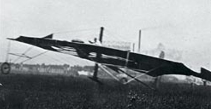
What eventually happened to the plane is unknown, but it was discarded in 1913. Vought, in an early 1913-newspaper interview, stated the umbrella plane was a “freak”, left the McCormick company and joined the Lillie organization.
McLeod Terrafly

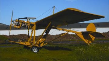
Designed to capture the spirit of the Santos Dumont Demoiselle, in developing this aircraft over 19 years, designer Kevin McLeod set out to produce a simple, rugged ‘back to basics’ machine that he hoped would be fun to fly.

The Terrafly is an original design ultralight aircraft built under the provisions of Australian ANO 95-10. Work started on the project in 1984.

The Terrafly is a single engine, high-wing, tail-dragging monoplane with conventional three axis controls. As with the Demoiselle, the pilot sits under the wing with the propeller wash in his face. The open cockpit has an airspeed indicator, altimeter, a dual CHT/EGT gauge, compass, clock, a G-meter, a Hobbs Hour Meter and fuel sight gauge.

The only example of the Terrafly built, registered 10-0571, was not test-flown and so information on its performance has never been established. The aircraft was donated to the South Australia Aviation Museum in October 2006 by the owner/designer.

Engine: Rotax 377 35 hp
Cruising Speed: 55 kt (100 kph) estimated
Maximum take-off weight: 225 kg
Length: 5.54 m
Wingspan: 7.62 m
Height: 2.6 m
Capacity: 1 pilot

McCandless M-4 / WHE Airbuggy

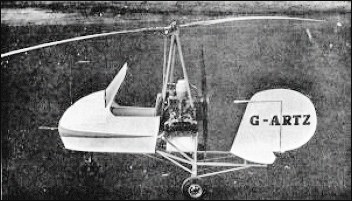
The McCandless M4 was a British single-seater ultra-light autogyro first flown in 1961. The original McCandless M4, developed by Rex and Cromie McCandless, was powered by a Triumph motor-cycle engine, this was later briefly replaced by a Norton motor-cycle engine which was abandoned in favour of a Volkswagen flat-four four-cylinder horizontally-opposed air-cooled engine which could be connected to the propeller without gears.
W. H. Ekin (Engineering) Company Ltd was formed at Crumlin, Co. Antrim, Northern Ireland, March 1969 to undertake production of six McCandless gyroplanes. The first one flew in February 1972. Extensive redesign was then undertaken and new prototype flew February 1973. Modified type called WHE Airbuggy.
There were two prototypes, one M1 and one M4 at the Ulster Folk and Transport Museum.
One flying VW engine-driven M4 type had the registration EI-ASR.
In total there were 8 built.

Cruising speed: 130km/h.

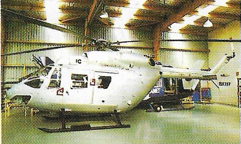
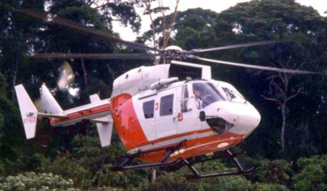
MBB BK.117 / Kawasaki BK.117 / IPTN NBK- 117

BK 117

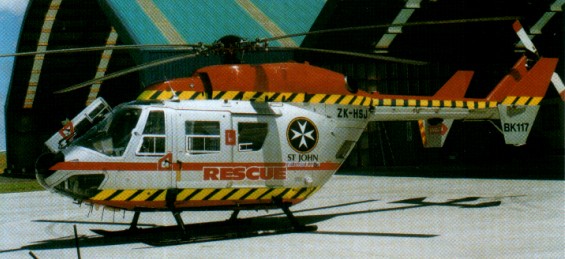
On 25 February 1977, MBB of West Germany and Kawasaki of Japan signed an agreement for the joint development of a twin-turbine utility helicop¬ter suitable for military as well as civil use, following more than two years’ negotiation. Joint development costs were to be divided equally, the financing being guaranteed by the respective governments. MBB was to be responsible for the main rotor and tail rotor, tail boom, empennage, hydraulic system and controls, while Kawasaki was to develop the landing gear, fuselage, transmission and other minor components. This emerged as the BK 117, which uses the BO 105’s rigid main rotor and a Japanese-developed transmission.

The original programme was based on four prototypes, two to be built by MBB in Munich and two by Kawasaki in Gifu, all to be completed by mid 1979. In each case, one of the prototypes was intended for flight testing and the other for static tests. However although the German company succeeded in completing its two models by the end of 1979, only one of the Japanese prototypes was ready on time.

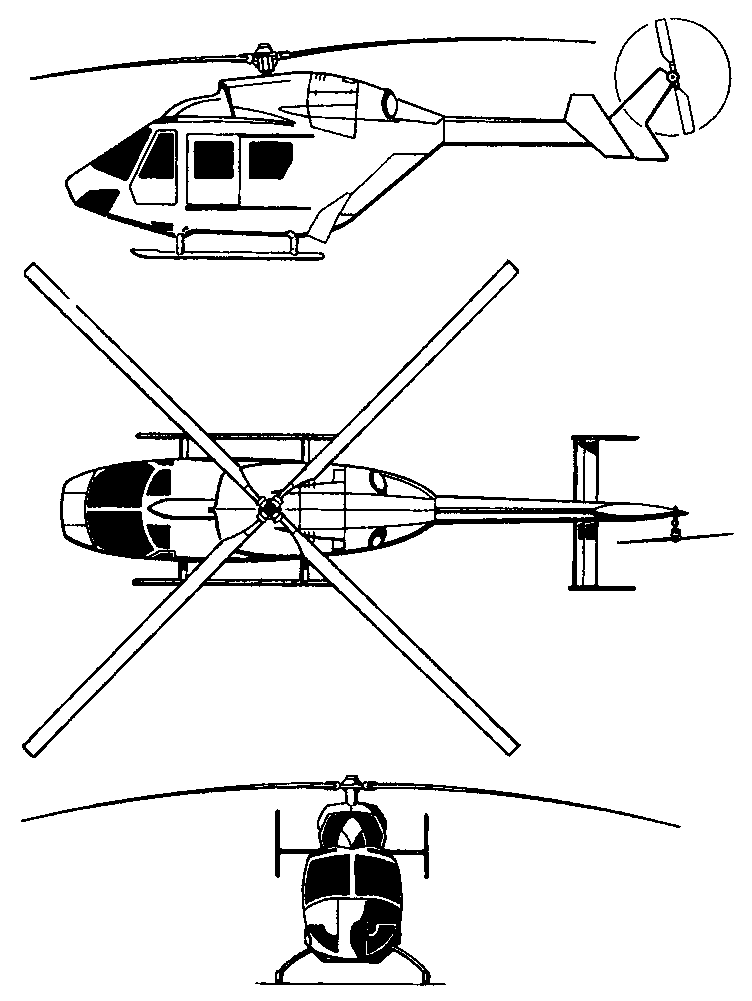
A fair percentage of parts and systems are identical to those of the German Bo.105 helicopter. The hydraulic system is based on the original Bo.105 version and even the rotor is taken from the Bo.105, suitably enlarged to match the demands of the bigger and heavier BK-117. The four-blade rotor is of the rigid type with a titanium hub and reinforced fiberglass blades. The transmission is derived from the Japanese KH-7 project: a seven-ten-seat helicopter which was to have been fitted with two 590shp Lycoming turbine engines. The BK-117 also has a pair of Avco-Lycoming LTS-101-650B-1 engines, delivering 600shp on take-off and 550shp maximum continuous power. The fuel tanks, with a total capacity of 605 liters, are housed in the lower part of the fuselage.

The executive version of the BK-117 carries a pilot and five passengers, but the volume of 3.22cu.m gives room for nine passengers in the high density version or in those used for commuter and offshore services to oil platforms. It can be loaded through two large sliding doors, one on either side of the fuselage. Behind the passenger cabin is a large baggage hold with a capacity of 1.34cu.m, which is reached through two hinged doors at the rear of the fuselage. A cargo hook can be fitted to the cabin floor for external lift work.

German and Japanese prototypes flew for the first time on 13 June 1979 (D-HBKA) and 10 August 1979 (JQ0003, the third BK.117) respectively. Kawasaki was first to fly a production aircraft (JQ1001) on 24 December 1981; MBB followed with D-HBKC on 23 April 1982, this machine being the first production aircraft to be delivered to a customer, in early 1983.

By the beginning of 1982, the BK-117 prototypes had logged more than 750 flying hours and type approval by the German Federal Authorities followed shortly afterwards. Half of the 130 aircraft ordered by February 1982 were for customers in the United States, where deliveries began in early 1983, from two production lines, in Germany and Japan.

Combining utility troop trans¬port and anti-tank capability, the BK.117A-3M was originally conceived as a contender for the Belgian Aeromobility 1 requirement. Based on the civilian BK.117A-3 airframe, the A-3M is offered in a multirole military configuration equipped with an under-nose Lucas 12.7mm or 0.5in gun turret with helmet sight, HOT anti-tank missiles with stabilised roof mounted sight, rocket pods, AAMs, and an ECM and Racal radar warning system, managed by a Racal 3000 Series avionics management system. Provision is also made for a mast mounted sight. Up to 11 troops can be carried in the utility role. Powered by twin Lycoming LTS1O1-650B-1 turboshafts, the BK.117 A-3M has a maximum take-off weight of 3,200kg and an operating range (minus auxiliary tanks) of 495km. MBB later abandoned its armed military BK 117A-3M.

The 1990 production version was the BK.117B-1. This was certificated in 1987 and is powered by two 592 shp (442 kW) Textron Lycoming LTS 101-750B-1 turboshafts.

BK 117 B1

The B-2 model has an increased MTOW and an extended C of G range.

Germany’s ministry of defence used one BK 117 as a composites testing aircraft.

More than 180 BK 117s had been delivered from the production lines in Germany and Japan by 1990.
The BK 117M is a military version, six.of which were delivered for trials with the West German Army.

An agreement was concluded in 1982 for the type to be built in Indonesia under licence by IPT Nurtanio as the NBK-117.

By January 1990 more than 250 BK 117s had been delivered worldwide, including 36 by Kawasaki, the standard aircraft being the BK 117B-1.

Since April 1990 a BK 117 engine testbed has been flying equipped with Turbomeca Arriel turboshafts in an effort to offer customers an alternative engine, and certification was scheduled for 1992.

On 1 September 1991, MBB transferred its Helicopter Division to Eurocopter Hubschrauber GmbH. This was later integrated with Aerospatiale’s helicopter interests into the Paris-based Franco-German Eurocopter Holdings, along with the NH-90, BO 105, BO 108 and BK 117.

Gallery

Variants:

BK 117A-1
Initial production version with LTS 101-650B-1 engines

BK 117A-3
Certificated in March 1985 with larger tail rotor fitted with twisted blades and take-off weight increased to 3200kg

BK 117A-4
Certificated in July 1986 with increased transmission limits at take-off power, improved tail rotorhead, and extra internal fuel (on German aircraft), all giving enhanced performance

BK 117 B-1
Fitted with more-powerful LTS 101-750B-1 engines to provide further increased performance and 140kg more payload; certificated in 1987

BK 117M
Military version of A-1 proposed by MBB in 1985, and flying since 1988; fitted with taller skids, a Lucas turret mounted under the fuselage houses a Browning 12.7mm automatic machine-gun and 450 rounds of ammunition, controlled by a helmet-mouted sight; outrigger pylons can carry up to eight HOT II or TOW antitank missiles, air-to-air missiles, rocket-pods, or forward-firing cannons; a doorway gunners position with a 12.7mm gun can also be installed, or 11 troops can be carried

Specifications:

MBB/Kawasaki BK 117
Engine: 2 x Lycoming LTS101-650B-1, 650 shp / 410kW
TBO: 2400 hr
Main rotor: 36.1 ft / 11m
Seats: 8/10
Length: 32.7 ft / 9.91m
Length rotors turning: 13m
Height: 10.9 ft / 3.83m
Max ramp weight: 6283 lb
Max takeoff weight: 6283 lb / 2850kg
Standard empty weight: 3505 lb / 1650kg
Max useful load: 2778 lb
Max landing weight: 6283 lb
Max sling load: 2645 lbs
Disc loading: 6.1 lbs/sq.ft
Power loading: 7.4 lbs/hp
Max usable fuel: 1058 lbs
Max rate of climb: 1830 fpm
Service ceiling: 17,000 ft / 4570m
Hover in ground effect: 11,000 ft
Hover out of ground effect: 8700 ft
Max speed: 150 kts
Normal cruise @ 3000 ft: 139 kt / 250km/h
Fuel flow @ normal cruise: 463 pph
Endurance @ normal cruise: 2.1 hr
Range max payload: 500km

BK.117
Engine: 2 x Lycoming LTS 101-750A3, 986 shp
Empty wt: 1849 kg
Cruise: 130 kts
Range: 540 km (340nm)

BK.117B-2
Engine: 2 x Lycoming LTS 101-750B-1
Instant pwr: 548 kW
Rotor dia: 11 m
MTOW: 3350 kg
Useful load: 1595 kg
Max speed: 150 kts
Max cruise: 133 kts
Max range: 540 km
Crew: 2
Pax: 10
Seats: 8/11.

BK.117C-1
Engine: 2 x Turbomeca Arriel 1E2
Instant pwr: 574 kW
Rotor dia: 11 m
MTOW: 3350 kg
Useful load: 1585 kg
Max speed: 140 kts
Max cruise: 133 kts
Max range: 540 km
Crew: 2
Pax: 10
Seats: 8/11

BK.117M
Engines: two 592-shp (441-kW) Lycoming LTS 101-650B-1 turboshafts
Maximum speed 155 mph (250 km/h) at sea level
Initial climb rate 1,476 ft (450 m) per minute
Service ceiling 15,000 ft (4,570 m)
Range 308 miles (495 km)
Empty weight 5,644 lb (2,560 kg)
Maximum take-off weight 7,055 lb (3,200 kg)
Main rotor diameter 36 ft 1 in (11.00 m)
Length overall, rotors turning 42 ft 8 in (13.00 m)
Height 11ft 0.3 in (3.38 m) to top of rotor head
Main rotor disc area 1,022.96 sq ft (95.03 sq.m)
Armament: one 0.5-in (12.7-mm) machine gun and disposable weapons
Hardpoints: 2