Vermont Gull Wing

Schill Gull Wing NX6929

The 1929 Vermont Air Transport Co Gull Wing was constructed at Harrison NJ. The four place Gull Wing featured two side-by-side cockpits. Wide-chord, birdlike wings permitted landings in 300-400′.

The one built NX6929, planned for entry in the Guggenheim competition, but was damaged beyond repair in a rough-field landing at St Albans VT.

Schill Gull Wing NX6929

Engine: Anzani
Max speed: 80 mph
Stall: 30 mph
Seats: 4

Vernander Swallow / Самолет АПВ

Designed by a collective [Аэроплан АПВ (Коллективный)] in 1909 under Alexander Petrovich Vernander (Александр Петрович ВЕРНАНДЕР – 1844-1918), professor of the Military Academy of Engineering, then second chief of the engineering bureau in Gatchina. Among the seven aircraft constructed in Gatchina one was christened „ласточку“ – swallow – a triplane that followed the Wright design but with curved wings, its propulsion consisting of a 25 hp REP engine, that drove two inward slanted propellers via bevel gear, to centre the air stream onto the rudder’s sides. Construction began in St. Petersburg in 1909, but the machine was not completed when construction ended in 1910.

VFW Fokker SG 1262

The German VFW SG 1262 Schwebegestell (hover rig) was designed and built in 1965 by Vereinigte Flugtechnische Werke (VFW) as an experimental aircraft to assist with the development of several vertical takeoff and landing (VTOL) military aircraft types that included the VFW VAK 191B, the EWR VJ 101 and the Dornier Do 31 transport. The 1262 designation relates to the initial numbering of the VAK 191B project by Focke-Wulf.

As part of the development of the VFW-Fokker VAK 191B vertical take-off aircraft, it was necessary to configure and test the monitoring of its flight control system. In order to minimise costs and risks during the development of the 191B the SG 1262 rig was designed and built in 1966 to simulate essential functions. Of high importance was the necessity to test the fly-by-wire flight control system, a redundant flight controller and a self-diagnosis system. A total of approximately 650 hours of simulation time, 2,000 hours of test runs on system test benches and 6,900 hours of wind tunnel tests were documented during the design phase of the project.

The aircraft was based on a trapezoidal frame without any skin panels. Deviating from the vectored thrust engine concept of the VAK 191B, five Rolls-Royce RB.108 turbojet lift engines with 9 kN (2,000 lbf) thrust each were mounted vertically. In addition to extensive sensor equipment, the rig used an auxiliary gas turbine for autonomous electrical power supply supply, it was also fitted with a Martin-Baker ejection seat.

The aircraft was based on a trapezoidal frame without any skin panels. Deviating from the vectored thrust engine concept of the VAK 191B, five Rolls-Royce RB.108 turbojet lift engines with 9 kN (2,000 lbf) thrust each were mounted vertically. In addition to extensive sensor equipment, the rig used an auxiliary gas turbine for autonomous electrical power supply supply, it was also fitted with a Martin-Baker ejection seat.

The control commands were transmitted via an electrical control (fly-by-wire) system with mechanical feedback. The flight control system had triple redundancy and double electro-hydraulic servo units with integrated self-monitoring. The control commands for the three axes were accomplished with compressed air nozzles that were actuated by a 280 bar (4,000 psi) high-pressure hydraulic system, movement of the main engines for control purposes was deliberately omitted. A direct mechanical back up of the compressed air control system was provided for emergencies.

40 tethered flights were initially carried out using a fixed telescopic apparatus before the aircraft flew in free flight for the first time on 5 August 1966. 150 free flights were made during the 18-month test program, including a demonstration flight at the 1968 Hanover Air Show at Hanover-Langenhagen.

Despite the discontinuation of all German vertical take-off programs the findings from experiments with the SG 1262 and experience gained from the VAK 191B project were used by German engineers during the development of the Multi Role Combat Aircraft (MRCA) project which became the Panavia Tornado.

The SG 1262 is preserved and on display at the Bundeswehr Museum of German Defense Technology in Koblenz.

Powerplant: 5 × Rolls-Royce RB.108 turbojet, 9 kN (2,000 lbf) thrust each
Gross weight: 3,900 kg (8,598 lb)
Fuel capacity: 800 kg
Maximum speed: 75 km/h (47 mph, 40 kn)
Endurance: 12 minutes
Service ceiling: 200 m (660 ft)
Thrust/weight: 1.15
Crew: 1

VFW Fokker Fanliner

Built in collaboration with Grumman-American the Fanliner two-seat light aircraft with Wankel rotary engine, first flown in 1973. Grumman American decided not to market the Fanliner in the U.S. but VFW Fokker did borrow the Cheetah wing and horizontal tail to build their pusher.
It was re-engined in 1976 with a Dowty Rotol ducted propulsor. Based on the Fanliner’s promise, the Federal German Government awarded a contract for two Fantrainer prototypes with ducted fan engines, first flown in 1977 and 1978.

VFW Fokker VFW-614

The VFW 614 twin-turbofan shorthaul transport was first flown in July 1971. German certification had been gained on 23 August 1974 and the first production aircraft had flown on 28 April 1975, but only 19 aircraft (including prototypes) were completed, and most ended up in storage at Bremen after very short working lives. Production was halted in 1978.

VFW Fokker VFW-614 Article

The VFW Fokker VFW 614 short-haul transport entered service with the Danish airline Climber Air in November 1975.

Engine: 2 x Rolls-Royce M45H
Wing span: 70 ft 6.5 in
Length: 67 ft 7 in

VFW Fokker H-5

The success of the H3 version resulted in the construction of a follow-on 1969 H5 prototype which bore marked similarities to its predecessor. The H5 incorporated many H3 components, including rotor blades (although 0.6m longer), a modified H3 landing gear, along with H3 controls, tail, and tail boom. The cabin could also be opened with left-side seats capable of folding for litter loading and unloading. The larger H-5 cabin had five seats.

Like the H3, there was also no hydraulic system with the H5.

It was intended that the H-5 would be followed by the H-7 7/8 seater (construction of which was apparently started but not completed) and the much larger H-9. As it turned out, however, further development was abandoned in 1972 following the merger of VFW and Fokker.

VFW Fokker H3 Sprinter

In 1960 VFW began research to develop a VTOL concept that exceeded the capabilities of current helicopters. More than a dozen different concepts were investigated, and the concept that evolved promising the best growth potential, productivity, speed, and cost effectiveness was the H3-E Compound Helicopter configuration.

The H3-E was built with a mission as a three-seat executive transport, two-stretcher ambulance aircraft, or an agricultural system with a payload of up to 315kg.

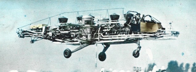
The design incorporated a compressed air and blade tip-drive rotor. The separate forward-thrust system consisted of fuselage-mounted fans.

The H3-E had a take-off weight of about 950kg and an empty weight of 500kg. The craft provided a payload weight of 265kg. The model had the capability of carrying a payload of almost 270kg with a fuel load of 205kg.

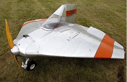
The completely enclosed fuselage was built around an aluminum alloy load-bearing keel which supported the cabin, landing gear, and engine bay structure, low-set tailboom with a V-tail, and a tricycle undercarriage. The cabin skin was fabricated of a glass-fiber reinforced plastic laminate.

The power unit was an Allison 400 shaft horsepower turbine engine which had a dual purpose. First, it was used to drive a centrifugal compressor in the hover mode. A duct delivered the compressed air through a flexible sleeve to the air distributor around the rotor shaft. Then, the high-pressure air traveled via flexible hose into the roots of the fully-articulated blades.

The overhead rotor consisted of a three-blade configuration and the blades used the NACA 23015 airfoil section. The speed range for the rotor varied from 280 to 480 revolutions per minute with a maximum loading of 15.7kg/sq.m.

When the air reached the end of each rotor, it was thrust through flush-mounted slot nozzles. A gearbox contained two bevel gears for the fans and a brake on the compressor shaft for switching the power to the compressor or to the fans. The mechanical layout of the system effectively eliminated the need for conventional transmission and driveshaft systems, hydraulic systems, and a tail rotor.

The technique to achieve near-vertical flight occurred when the rotor was slightly rotated in a standard helicopter style. With the increase in speed, the side-mounted fans were caused to free-wheel within their containing shrouds.

At a certain point in the trajectory, a decision that was made by the pilot, the transformation to full utilization of the fans could be made. Since the fans were already in a windmilling situation, the transition to full fan speed took only about two seconds to accomplish.

Hovering stability was mainly affected by blade hinge offset, blade pitch, angular velocity, disk loading, gross weight and mass moment of inertia of the aircraft,

Early in its program the H3-E underwent a number of test programs. An extensive blade fatigue test attempted to simulate the temperature and pressure cycles inside the blades. The test rig was fully automated, and every five minutes, the temperature and pressure increased and stabilized for 45 seconds before the blade vibrated.

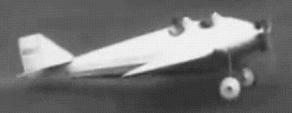
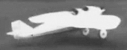
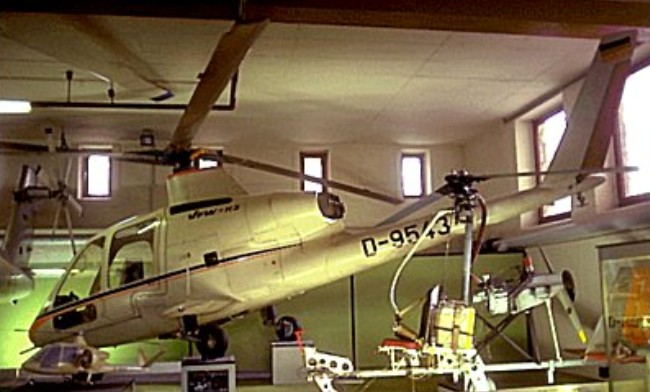
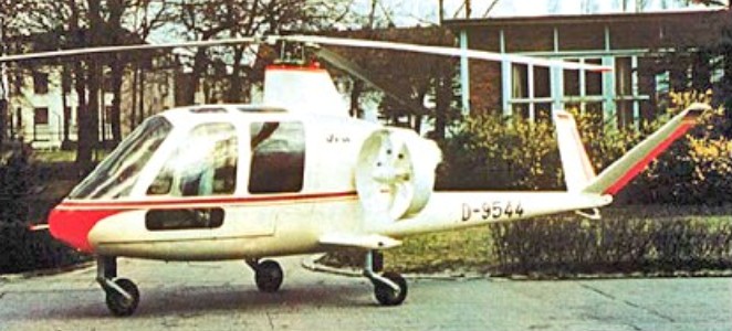
The only two prototypes of the H3 were constructed in 1968. Before flight, though, there were considerable ground shake tests accomplished. A sophisticated test rig excited the rotor head with a constant force independent of frequency. Ground tests also showed that the vehicle had certain mechanical instabilities at high rotor speeds. The first of two prototype H-3s (H3-E1, D-9543) flew in early 1970 without the external fan propulsion units.

Engine: 1 x Allison 250-C20 turboshaft, 300kW
Main rotor diameter: 8.70m
Rotor disc area: 60 sq.m
Length with rotors turning: 9.29m
Max height: 2.5m
Landing gear track: 2m
Max take-off weight: 968kg
Empty weight: 495kg
Max speed: 300km/h
Max cruising speed: 250km/h
Normal cruising speed: 242 kph
Max vertical rate of climb: 2m/s
Service ceiling: 3900m
Endurance: 2hr