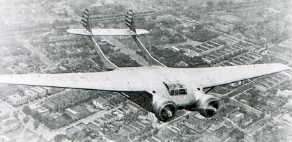
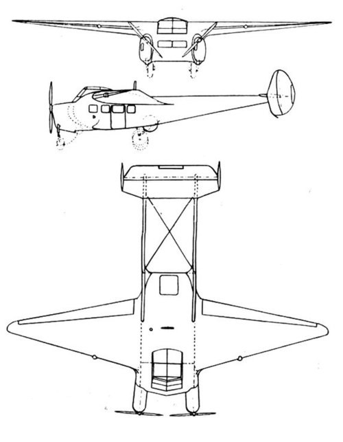
The Burnelli UB-14 and a developed variant named OA-1 Clyde Clipper were 1930s American prototype lifting-fuselage airliners designed by Vincent Burnelli, who was responsible for constructing the first two examples. Following on from his earlier designs Vincent Burnelli designed a commercial transport version using the lifting-fuselage concept. Burnelli’s designs were based on the idea that an airfoil-section fuselage could contribute to the lift generated. The Burnelli UB-14 first flew in 1934, and had an airfoil-section fuselage that formed the centre-section of the wing. The aircraft had twin tailbooms and a widespan tailplane and elevator fitted with twin fins and rudders. The UB-14 had retractable landing gear and was powered by two Pratt & Whitney radial engines. An enclosed cockpit for the crew of two was located on the centre wing’s upper surface. The cabin could hold 14 to 18 passengers. The first prototype, UB-14, was destroyed in a 1935 accident attributed to faulty maintenance on the aileron control system. Burnelli then designed and built an improved version, the UB-14B. An extensively modified version of the UB-14B design was built under licence in the United Kingdom by Cunliffe-Owen Aircraft, powered by two Bristol Perseus XIVC radials as the Cunliffe-Owen OA-1 Clyde Clipper. The UB-14B was to have been built by Scottish Aviation, but with more streamlined inline engines. Burnelli applied to the CAA for approval to fly a transatlantic flight with Clyde Edward Pangborn as the pilot in September 1936, however it failed its airworthiness certification due to an excessively long takeoff run and poor quality control. Its performance was later tested at A&AEE Boscombe Down in 1939.
After appropriate work, in June 1941 Jim Mollison and an Air Transport Auxiliary crew delivered the Cunliffe-Owen OA-1, now registered as G-AFMB to Fort Lamy, Chad. It was then fitted out as a personal transport for General De Gaulle. At one time it landed in Vichy France while en route to Fort Lamy. It was later abandoned at RAF Kabrit in Egypt, and burned during VJ-Day celebrations.
Variants UB-14 Prototype, powered by Pratt & Whitney engines, registered as NX14740. Built by Burnelli Company. Destroyed 13 January 1935, without injury. UB-14B Second prototype with modifications, registered as NC15320. Built by Burnelli Company. Exported to Nicaragua in 1943 as AN-ABH. OA-1 Third prototype, registered as G-AFMB, built by Cunliffe-Owen Aircraft under licence with further modifications, in the United Kingdom.
UB-14B Crew: two Capacity: 14–18 passengers Length: 44 ft 0 in (13.41 m) Wingspan: 71 ft 0 in (21.64 m) Height: 10 ft 0 in (3.05 m) Wing area: 686 sq ft (63.7 m2) Airfoil: Fuselage: NACA 4323 Outer wing root: NACA 2412 Outer wing tip: NACA 2409 Empty weight: 9,200 lb (4,173 kg) Gross weight: 17,500 lb (7,938 kg) Powerplant: 2 × Pratt & Whitney Hornet, 750 hp (560 kW) each Maximum speed: 210 mph (340 km/h, 180 kn) Cruise speed: 205 mph (330 km/h, 178 kn) Range: 1,240 mi (2,000 km, 1,080 nmi) Service ceiling: 22,000 ft (6,700 m)
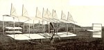
The 1910 Burgess A pusher biplane, also know as Herring-Burgess, was designed and built by W.Burgess (fuselage, wings, gear) and A.Herring (controls, engine and props). It suffered many changes.
Span: 26’9″ or 27′ or 33’4″ Length: 33′ or 26′ or 28’9″
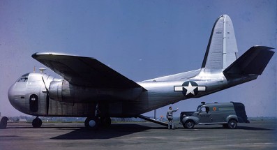
World War II created a great demand for military transport aircraft in the United States. Because of initial fears of a shortage of aluminum, the War Department explored the use of other materials for aircraft construction. Budd, the developer of the shotweld technique for welding stainless steel and a manufacturer of stainless steel railroad cars, automobile, bus, and truck bodies, hired an aeronautical engineering staff and worked with the U. S. Navy to develop a new twin-engine transport aircraft constructed primarily of stainless steel. The U.S. Navy accepted the proposal for the new aircraft, and placed an order for 200, to be designated RB-1. The U.S. Army Air Forces (USAAF) followed with an order for 600, designated C-93.
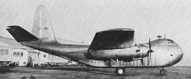
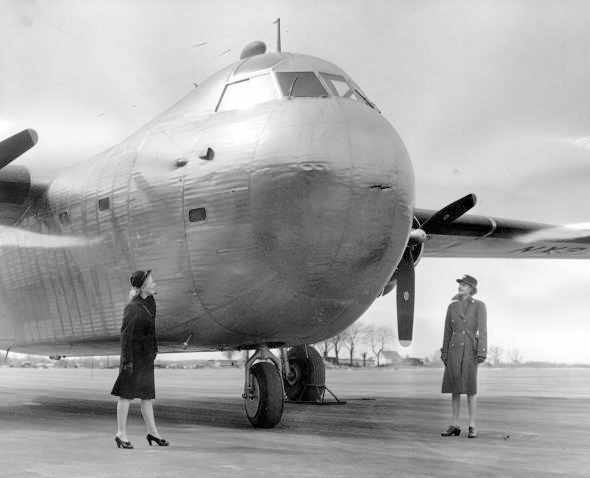
The Conestoga was a twin-engine high-wing monoplane with tricycle landing gear. The elevated flight deck was contained in a distinctive, almost hemispherical nose section. Its two 1,200 hp (890 kW) Pratt & Whitney R-1830-92 air cooled 14-cylinder, twin-row, radial engines, the same engines fitted to the C-47, drove three-bladed Hamilton Standard Hydromatic constant-speed, full-feathering propellers and powered a 24-volt electrical system. While the fuselage was thin-gauge stainless steel, only a portion of the wing was made of the metal; the trailing section of the wing and all control surfaces were fabric-covered.
The RB-1/C-93 introduced many of the features now standard in military transports. The flight deck could accommodate three crew members, pilot and co-pilot side-by-side, the navigator behind them. Stairs connected the flight deck to the cargo area, which was 25 feet (7.6 m) long with an unobstructed cross-section of 8 × 8 feet (2.4m) throughout its length.
Cargo loading and unloading could be accomplished in two ways: through 40 × 60 inch (102 × 152 cm) doors on both sides of the fuselage or by an electrically operated 10 × 8 foot (3.0 × 2.4 m) ramp at the aft end of the cargo area under the upswept tail, a similar development to what had been initially fitted to the Germans’ own Ju 90 four-engined transport aircraft as their Trapoklappe ramp in 1939.
The RB-1’s loading ramp, accessed by manually operated clamshell doors, along with the tricycle landing gear, meant cargo could be loaded/unloaded at truck-bed height. A manually operated two-ton (907 kg) hoist for unloading trucks and a one-ton winch for pulling cargo up the ramp were also provided in the cargo area. The aircraft could accommodate: 24 paratroopers, or 24 stretchers and 16 sitting wounded, or 9,600 pounds of cargo, or a 1½ ton truck, or The RB-1 could carry 9,600 pounds of payload, in addition to 390 US gallons of fuel.
The largest ambulance in use by the U.S. military.
The prototype first flew from the Budd Red Lion Factory Airfield in Philadelphia, Pennsylvania on 31 October 1943, piloted by Guy Miller. The prototype had a takeoff run when empty of just 650 feet (200 m), and could carry a maximum payload of 10,400 pounds (4,700 kg) with a takeoff run of 920 feet (280 m). However, the aircraft demonstrated greater than expected fuel consumption; the range with a standard payload was only 700 miles (1,100 km), 650 miles (1,050 km) with a maximum payload.
Three prototype aircraft: NX37097, NX41810, and NC45354 were built; one was used for testing radio equipment, while the other two were used for flight test evaluations. During testing, a few aircraft had difficulty with the simultaneous deployment of the right and left landing gear. With the same engines as the C-47, but 3,000 pounds (1,400 kg) heavier (empty), the aircraft was relatively underpowered.
At the Budd factory and airfield in Philadelphia, Pennsylvania, there were construction delays due to cost overruns and problems with stainless steel fabrication. By late 1943, aluminum production had been increased with the construction of new processing facilities, and other more conventional cargo aircraft (such as the Curtiss C-46 Commando and the Douglas C-47 Skytrain) were being produced in large numbers. This caused the Army to cancel its order for the C-93 and the Navy to reduce its RB-1 order from 200 to 25, of which 17 were delivered in March 1944.
On 13 April 1944, during a Naval Air Training Command (NATC) evaluation flight of RB-1 prototype U.S. Navy NX37097 at Patuxent River NAS, Maryland, the aircraft crashed, killing one of the crew. The aircraft was damaged beyond repair and written off, but the pilot reported that the stainless steel construction of the aircraft contributed to saving his life.
Production RB-1 aircraft never entered squadron service with the Navy, but a few were briefly used by Naval Air Stations as utility aircraft. With only 17 aircraft in inventory, the RB-1 was not feasible to maintain on the active list, and it was retired from U.S. Navy service in early 1945.
The extant RB-1s were then transferred to the War Assets Administration (WAA) to be sold as war surplus. In 1945, the WAA sold 12 Conestogas to the National Skyway Freight Corp for $28,642 each. The new company, founded by members of the AVG Flying Tigers immediately sold four RB-1 aircraft to other buyers, which paid for the entire WAA contract.
The seven remaining National Skyways aircraft were used to transport a variety of cargo, shipping fruit and furniture from its base in Long Beach, California. Pilots reported that the Budd transports were temperamental; in particular, exhaust stacks kept falling off and causing engine fires. There were three more crashes of Conestogas while in service with National Skyway Freight, one each in Virginia, New Mexico, and Michigan. The crash in Virginia was a belly landing at a country club brought on by fuel exhaustion following weather-related problems. The Albuquerque, New Mexico crash was due to a downdraft during a snow storm, 80 miles (130 km) from Albuquerque. Pilot and co-pilot were killed when they were thrown through the windshield and the aircraft skidded over them; the flight engineer survived.
In 1947, the U.S. Army (and later the U.S. Air Force) gave National Skyway Freight a large contract for trans-Pacific freight, for which it leased military aircraft. The company changed its name to Flying Tiger and replaced the RB-1s with C-47s for its U.S. freight routes; the RB-1s were sold off to other buyers. One of these aircraft, a prototype RB-1, “NC45354” was sold to the Tucker Motor Company to transport its demonstration 1948 Tucker Sedan to auto shows around the U.S.; it was reportedly later abandoned at an airfield in Oakland, California after repeated mechanical troubles.
In Brasil, Viação Aérea Santos Dumont started with the purchase of two Catalinas and a Budd Conestoga, both former Rubber development Corporation. The RB.1, registered PP-SDC “Tio Sam” was damaged in an emergency landing at Campo dos Afonsos on 04.01.1947, landing on one engine, declared unrecoverable and there scrapped.
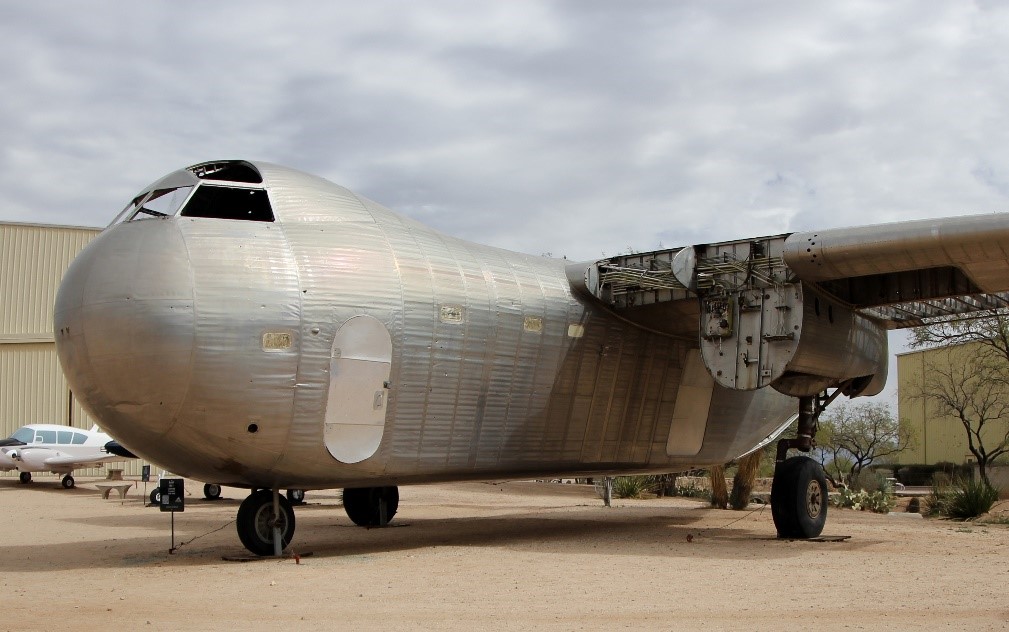
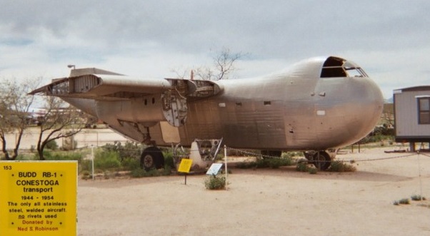
A single unrestored Budd RB-1 BuNo 39307 is on display at the Pima Air & Space Museum in Tucson, Arizona.
RB-1 Engines: 2 × Pratt & Whitney R-1830-92, 1200 hp (890 kW) each Wingspan: 100 ft 0 in (30.48 m) Wing area: 1,400 ft2 (130.06 m2) Length: 68 ft 0 in (20.73 m) Height: 31 ft 9 in (9.68 m) Empty weight: 20156 lb (9143 kg) Gross weight: 33860 lb (15359 kg) Maximum speed: 197 mph (317 km/h) Cruise speed: 165 mph (266 km/h) Range: 700 miles (1127 km) Crew: 2 Capacity: 24
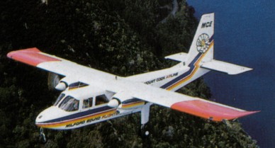
In 1962 the two partners, John Britten and Desmond Norman, decided to build a plane of their own. The essential factors were low cost, all-weather construction, twin engine reliability and a good payload. The design was of classic simplicity: a one-piece wing with no dihedral, Hoerner-type tips, slab-sided fuselage with seating for up to 10 passengers. The prototype was powered by two 210-hp Continental engines with a fixed tricycle undercarriage. Bench-type seats for two people eliminated the need for a central aisle and these were accessed by three doors, two port and one starboard, with the rear door being of extra width to allow ease of cargo loading. The Islander can also be operated as a freighter carrying more than a ton of cargo. Passenger baggage is stored in a large 30 cu.ft. bin behind the cabin with an access door on the port side. The first metal was cut in September 1964 and the aircraft was hand crafted on a “Dexion” jig. The prototype took to the air for its first flight of 70 minutes on 13 June 1965 with both John Britten and Desmond Norman at the controls. There were some shortcomings which an increase in wing span by 1.22 metres and more powerful Avco Lycoming 260-hp engines cured.
A choice of wings was offered, so the plane could be fitted with the standard 49-foot-span wings or extended 53-foot wings, using raked tips and auxiliary fuel tanks. Delivery of the Islander began in August 1967, but the great number of orders from over 50 countries forced Britten-Norman to subcontract manufacture of a number of the mini-airliners to the British Hovercraft Corporation. Others were produced in Romania by IRMA which was then trucked to Bembridge for completion. Buyers were able to choose Lycoming engines: 260 or 300 hp. A Rajay turbocharging unit increased the Islander’s twin-engine ceiling to 26,000.
Britten Norman developed two other variants for demonstration at the 1976 Farnborough Show, the “Firefighter” and “Agricultural Islander”. While both designs proved themselves technically, no orders were forthcoming and the variants were shelved. Arrangements were made with Rornaero in Bucharest, Romania, to produce the airframes. The engines, propellers, and undercarriage are trucked across Europe to where the aircraft are assembled under UK CAA supervision then, with basic instrumentation and a pilot’s seat fitted, the aircraft is flown in dull grey primer to Bembridge to be completed to customer’s requirements. The BN-2 Super was developed by inserting a 33-inch plug in the fuselage of the production prototype, G-ATWU, allowing for an additional row of seats, however, the version was never put into production. To increase the Islander’s hot and high performance Lycoming IO-540K 300-hp fuel-injected engines were fitted. Another modification involved fitting wingtip tanks which increased the span to 53 feet while droop flaps and droop leading edges increased performance. The first turbine powered Islander flew in April 1977. Designated the BN2A-41, it was powered by Lycoming LTP 101 turboprops and, although its performance was described as “sparkling”, it was overpowered and the fitting of the engines required major wing modifications. The project was discontinued. In 1980 the production BN2T Turbine Islander took off with Allison 250 B17C engines. Wing fences were fitted to improve stall recovery and the prototype headed off for hot and high in Kenya and to Finland for cold weather trials. Pilatus introduced a beefed up Islander, the BN2B, featuring a 300 pound increase in landing weight, including the BN-2B-20 and BN-2B-26.
In 1979 it was decided to diversify, looking at different roles as against taking people. Those sort of roles are fisheries protection, border patrol and parachuting etc. In 1978 they looked at putting a more sophisticated airborne radar into the aircraft, entering into a joint venture with Thorn EMI, using their Skymaster radar to increase the ground warning time from three or four minutes to 20 30 minutes. The name “Defender” came at that point, referring to an Islander with four wing mounted hardpoints. Stressed to take 750lbs on the inboard pair and 350lb outboard, the hardpoints designed to carry long range fuel tanks or military stores.
Available with 260 hp, turbo-charged 260 hp, or 300 hp engines, and optional 28 cu.ft. capacity nose extension.
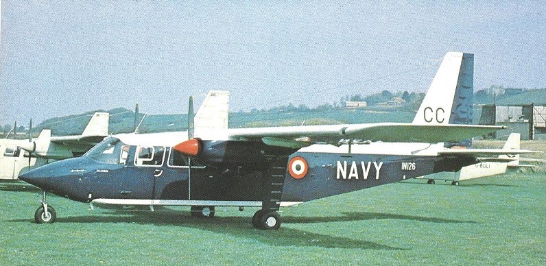
Defender – For general military duties PBN developed the Defender from the basic piston-engined Islander utility aircraft and, with the introduction of the Allison 250-B17C powered Turbine Islander, a parallel turbine Defender was offered. The Defender is capable of a wide range of military roles including troop trans¬port, SAR, forward air control, electronic warfare, logistic support, and medevac.
Operationally launched by PBN on March 6, 1987, The AEW Defender is a low-cost AEW system offered in conjunction with Thorn-EMI’s Skymaster lightweight multi-mode pulse-Doppler track-while-scan radar. Acquisition and tracking of targets is auto¬matic, and air-to-air/air-to-ground datalinks, 1FF and navigation systems may be fully integrated with the radar’s display and control system. The Skymaster system can also be used to detect surface vessels during maritime reconnaissance missions. A large undernose radome houses the 360’-scan antenna. With appropriate computer software modifications, the AEW Defender/Skymaster combination is being offered as a solution to the British Army’s Astor requirement for an airborne battlefield surveillance radar. The British Army has bought Defender AL Mk 1s to replace Beavers.Another Defender has been flown with a Ferranti surveillance radar installed in connection with the Army’s earlier Corps Airborne Stand-Off Radar (Castor) requirement. The AEW Defender is based on the BN-2T Turbine Defender airframe.
The Maritime Defender is designed for coastal patrol, fishery and oil rig protection, and SAR durties. The Maritime Defender has Bendix RDR-1400 search radar in the nose, and four under-wing pylons to carry weapons, survival packs or other items. Either 6600 lb maximum all up weight piston engined or 7000 lb MAUW turbine powered, the aircraft comes with both Omega and short range sector scan radar.
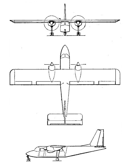
The Defender was officially added to the ranks of the British Army on March 10th, 1989. Design is wholly utilitarian and is most characteristically defined by the high-mounted monoplane wings. Each wing maintains an Allison 250-B17F turboprop engine powering a three-bladed propeller. The cockpit compartment is held well forward in the squared off fuselage with slab sides and features a useful sloped nose for improved downward visibility. The undercarriage is a conventional tricycle arrangement and made up of two double-tired main landing gear legs and a single-tired nose landing gear leg – as a whole, the undercarriage is non-retractable. The empennage is dominated by a single large-area vertical tail fin clipped at the top and sporting some sweep along the leading edge. Horizontal tailplanes are affixed to the vertical fin tail. Typical accommodations are for two pilots and up to six passengers. Entry/exit is via side doors, two forward and two aft. Her gross weight is listed at 7,000lbs. Each wing can field four hardpoints for various munition options to include gun pods, rocket pods and bombs if need be or external fuel tanks for extended loitering times and operational range. Specialized reconnaissance and surveillance mounts are fitted with applicable tailored equipment, cameras and jamming pods as well as communications options. Airborne Early Warning (AEW) Defenders sport a hideous-looking nose radome that quickly identifies the type and its role.
In 2003, the UK military purchased three (some sources state four) Defenders to help with the deteriorating conditions in Iraq following the 2003 coalition invasion. These aircraft carried the designation of Defender 4S AL Mk 1 and sported underwing dispensers to protect against surface-to-air guided munitions. This model was furthered defined by the implementation of an electro-optical turret under the extreme end of the nose.
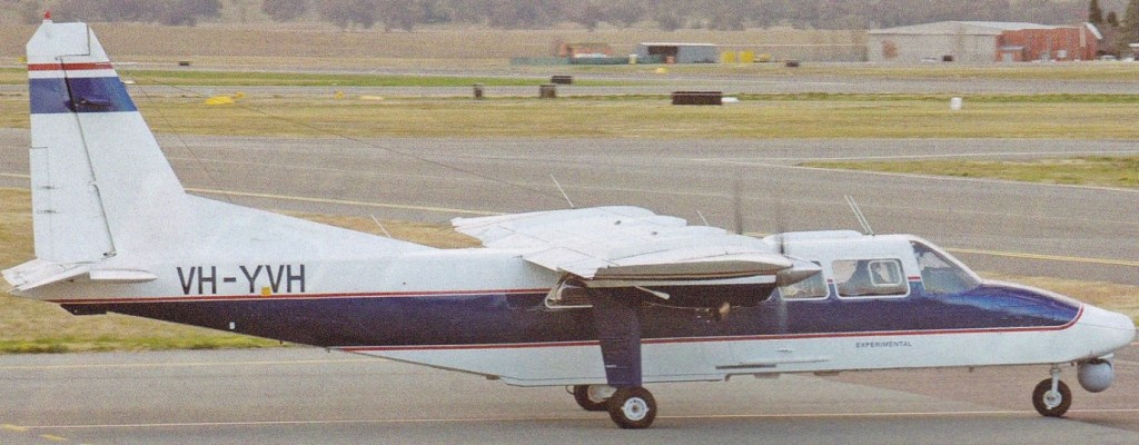
The Defender 4000 is a military version of the Defender series and first flight of this system was achieved in August of 1994. The Defender 4000 features a larger wing component similar to that of the Trislander and operates with increased weight tolerances. Her engines are more powerful than previous versions and has an enlarged nose section for the fitting of search radar. Top speed is a reported 225 miles per hour.
BN-2T-4S Defender 4000
By 1990, over 1,100 Islanders have been built with Lycoming piston engines or, in the BN-2T Turbine Islander, two 400 shp (298 kW) Allison 250-B17C turboprops.
In 1970, Britten-Norman introduced an enlarged version of the twin-engine Islander with a third engine mounted high on the tail in a tractor position. The three engines were 260-hp 0-540-E4C flat-sixes turning Hartzell two-blade constant-speed fully feathering propellers. Three versions of the Trislander are the BN-2A Mk 111-2 (a standard version with extended nose baggage compartment), the BN-2A Mk 111-3 (with an automatic feathering system for the props), and the BN-2A Mk 111-4 (with a rocket engine for additional thrust if an engine fails on takeoff).
Britten Norman BN-2 Islander (1968) Powerplant: two Lycoming O-540-E4B5, 260 bhp Propellers: Hartzell constant-speed feathering two-blade 80 in diameter. Wingspan, 49 ft Length, 35 ft 71 in Height, 13 ft 8 in Gross wing area, 325 sq.ft Max. usable floor area, 43.4 sq.ft Max. usable cabin volume, 140 cu.ft Max. cabin length, 160 in including flightdeck Max. width, 43in Max, height, 51 in. Accommodation: max. high density seating 9 passengers and pilot at 30 in pitch Basic operational weight, 3280 lb Total fuel, 800 lb Max. take-off, 5500 lb Max. landing, 5500 lb Max. payload (volume limited), 1920 lb Max. zero fuel, 5200 lb Power loading (max. take-off weight), 10.6 lb/hp Wing loading (max. take-off weight), 16.95 lb/sq.ft Wing loading (max. landing weight), 16.95 lb/ft High-speed cruise, 138 kt. at 6500 ft Long-range cruise, 132 kt. at 13,000 ft Approach speed, 62 kt Take-off field length, ISA at sea level, 1000 ft Landing field length, ISA at sea level, 990 ft Range with allowances, max. fuel, 1450 lb payload, 738 nm
BN2A-8 Engine: 2 x Lycoming O-540-E4C5, 260 hp. Seats: 10. Wing loading: 19.6 lb/sq.ft. Pwr loading: 12.7 lb/hp. Gross wt: 6200 lb. Empty wt: 3400 lb. Equipped useful load: 2449 lb. Payload max fuel: 1633 lb. Range max fuel 75% pwr: 564nm/4hr. Range max fuel 55% pwr: 625nm/5.3hr. Service ceiling: 13,000 ft. 75% cruise: 139 kt. 55% cruise: 119 kt. Vmc: 39 kt. Stall: 44-50 kt. 1.3 Vso: 57 kt. ROC: 950 fpm. SE ROC: 170 fpm @ 65 kt. SE service ceiling; 4450 ft. Min field length: 1160 ft. Fuel cap: 816 lb.
BN2A-9 Engine: 2 x Lycoming O-540-E4C5, 260 hp. Seats: 10. Wing loading: 20.3 lb/sq.ft. Pwr loading: 12.12 lb/hp. Gross wt: 6,300 lb. Empty wt: 3250 lb. Equipped useful load: 2699 lb. Payload max fuel: 1523 lb. Range max fuel/75% pwr: 856nm/6.1hr. Range max fuel / 55% pwr: 934nm/7.9hr. Ceiling: 13,000 ft. 75% cruise: 139 kt. 55% cruise: 119 kt. Vmc: 39 kt. Stall: 44-50 kt. 1.3 Vso: 57 kt. ROC: 950 fpm. SE ROC: 170 fpm @ 65 kt. SE ceiling: 4450 ft. Min field length: 1160 ft. Fuel cap: 1176 lb.
BN-2A-20 Engine: 2 x Lycoming IO-540-K1B5, 300 hp. Seats: 10. Wing loading: 19.6 lb/sq.ft. Pwr loading: 11 lb/hp. Gross wt: 6560 lb. Empty wt: 3640 lb. Equipped useful load: 2569 lb. Payload max fuel: 1753 lb. Range max fuel 75% pwr: 534nm/3.6hr. Range max fuel 55% pwr: 609nm/4.7hr. Service ceiling: 18,000 ft. 75% cruise: 147 kt. 55% cruise: 131 kt. Vmc: 39 kt. Stall: 44-50 kt. 1.3 Vso: 57 kt. ROC: 1130 fpm @ 57 kt. SE ROC: 225 fpm @ 75 kt. SE service ceiling; 3,100 ft. Min field length: 1100 ft. Fuel cap: 816 lb.
BN-2A-21 Engine: 2 x Lycoming IO-540-K1B5, 300 hp. Seats: 10. Wing loading: 20.3 lb/sq.ft. Pwr loading: 11 lb/hp. Gross wt: 6600 lb. Empty wt: 3695 lb. Equipped useful load: 2554 lb. Payload max fuel: 1378 lb. Range max fuel 75% pwr: 799nm/5.4hr. Range max fuel 55% pwr: 924nm/7.1hr. Service ceiling: 18,000 ft. 75% cruise: 147 kt. 55% cruise: 131 kt. Vmc: 39 kt. Stall: 44-50 kt. 1.3 Vso: 57 kt. ROC: 1130 fpm. SE ROC: 225 fpm @ 75 kt. SE service ceiling; 3,100 ft. Min field length: 1100 ft. Fuel cap: 1176 lb.
Britten-Norman BN-2A-21 Maritime Defender Engines: 2 x Avco Lycoming IO-540-K1B5, 300 hp Length: 36.319 ft / 11.07 m Height: 12.402 ft / 3.78 m Wingspan: 53 ft ft / 16.15 m Wing area: 342.295 sq.ft / 31.8 sq.m Max take off weight: 6593.0 lb / 2990.0 kg Weight empty: 4013.1 lb / 1820.0 kg Max. speed: 157 kts / 290 km/h Cruising speed: 148 kts / 274 km/h Service ceiling: 18045 ft / 5500 m Endurance (2 x 56 Imp.Gal. drop tanks): 15 hr.
BN2B First built: 1967. Engine: 2 x Lycoming O-540-E4C5, 260 hp. TBO: 2000 hrs. Prop: Hartzell 2 blade, constant speed 80 in. Seats: 10. Length: 35.7 ft. Height: 12.4 ft. Wingspan: 49 ft. Wing area: 325 sq.ft. Wing aspect ratio: 7.4. Max ramp wt: 6600 lbs. Max take off wt: 6600 lbs. Standard empty wt: 3612 lbs. Max useful load: 2988 lbs. Max landing wt: 6300 lbs. Wing loading: 20.3 lbs/sq.ft. Power loading: 11 lbs/hp. Max useable fuel: 1176 lbs. Climb rate: 1130 fpm @ 65 kts. Climb gradient: 1043 ft/nm. Rate of climb @ 8000 ft: 550 fpm. Service ceiling; 18,000 ft. SE rate of climb: 225 fpm @ 62 kts. SE climb gradient: 218 f/nm. SE ceiling: 7000 ft. Max speed: 139 kts. Cruise @ 65% power @ 8,000ft: 135 kts. Fuel flow @ 65% power @ 8,000ft: 160 pph. Endurance @ 65% power @ 8,000ft: 7.1 hr. Stalling speed clean: 49 kts. Stall speed gear/flaps down: 42 kts. Turbulent air penetration speed: 107 kts. Fixed undercarriage. Wing load: 19.27 lb/sq.ft / 94.0 kg/sq.m Maximum range: 1134 nm / 2100 km Crew: 2+2 Payload: 8Pax / 1015kg
BN-2T Engines: 2 x Allison 250-B17C
Turbine Defender Engine: 2 x Allison 250 600 kW, 480 kW. Span: 14.9 m. Length: 10.9 m. Wing area: 30.2 sq.m. Empty wt: 1914 kg. MTOW: 3175 kg. Payload: 1270 kg. Cruise speed: 285 kph. Initial ROC: 320 m / min. Ceiling: 7620 m. T/O run: 225 m. Ldg run: 228 m. Fuel internal: 814 (+454) lt. Range: 1350 km. Capacity: 10 pax.
Britten-Norman BN2T-4S Defender 4000 Engines: 2 x Allison 250-B17F/1 turboprop, 400 shp Props: 3 blade, 80 in. Length: 35.86ft (10.93m) Width: 48.98ft (14.93m) Height: 13.78ft (4.20m) Maximum Speed: 225mph (362kmh; 195kts) Max cruise: 178 kts ROC: 1210 fpm. SE ROC: 223 fpm Maximum Range: 437miles (703km) External Fuel Tanks capacity: 2,500lbs Accommodation: 2 + 6 Hardpoints: 4 Empty Weight: 4,998lbs (2,267kg) Maximum Take-Off Weight: 8,499lbs (3,855kg)
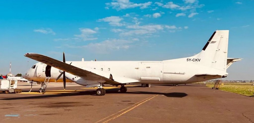
A product of British Aerospace at its Manchester facilities, the ATP is the stretched and updated development of the HS 748 (formerly Avro, latterly BAe 748), production of which ceased in 1989.
Development of the BAe ATP / Jetstream 61 started in 1984 as a short-range, low-noise, fuel-efficient turboprop aircraft. The airframe of the Avro 748 was re-designed and lengthened 5.03 m (16.5 feet), the wing re-designed, and minor modifications were made to the nose and tail shapes. The six-blade Hamilton Standard composite propellers were driven by 1,978kW / 2,653shp Pratt & Whitney Canada PW126 engines. The British Aerospace Advanced Turboprop or ATP is a twin turboprop airliner for up to 72 passengers. Passenger accommodation totals 64 at 31-in (79-cm) seat pitch in a fuselage similar to that of the 748 but 16 ft 6 in (5,03 m) longer. Other changes included smaller and closer-pitched cabin win¬dows, a wider centre section for the wing (adapted from the Andover), new landing gear, a redesigned flight deck with EFIS instrumentation, and new electrical, hydraulic and environmental control (air conditioning) systems. The ATP programme was launched in March 1984, and the prototype, G-MATP s/n 2001, was flown first on 6 August 1986. Certification was granted in March 1988 and the ATP entered airline service in May 1988 with British Midland Airways.
By the end of October 1990, 39 aircraft had been ordered with some 12 further options held, and 30 machines had been delivered to six airlines. Production in 1991 was running at about 12 aircraft a year, and depending on specification, the new cost is between $US112.5 and US$13.0 million. In 1994, a modified version with Pratt & Whitney Canada PW127D engines was introduced under the name Jetstream 61. The BAe ATP and Jetstream 61 failed to attract significant orders. The ATP / J61 saw a limited production run. 63 ATPs and 1 Jetstream 61 were built. Production ended in 1998. In 2001, the ATP Freighter project started, with 6 ATPs to be converted into cargo aircraft for West Air Sweden. The ATPF is capable of carrying eight LD3 containers or six LD4s when fitted with the Large Freight Door, or loading up to eight tonnes. The ATPF made it first flight on 10 July 2002. Since then, 12 ATPs were converted into ATPFs.
ATP Engine: 2 x 2653hp Pratt & Whitney Canada PW126 turboprops Take-off weight: 22930 kg / 50552 lb Empty weight: 13595 kg / 29972 lb Wingspan: 30.63 m / 100 ft 6 in Length: 26.00 m / 85 ft 4 in Height: 7.14 m / 23 ft 5 in Wing area: 78.3 sq.m / 842.81 sq ft Cruise speed: 496 km/h / 308 mph Ceiling: 7600 m / 24950 ft Range: 1825 km / 1134 miles Passengers: 64
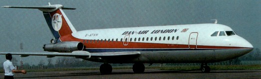
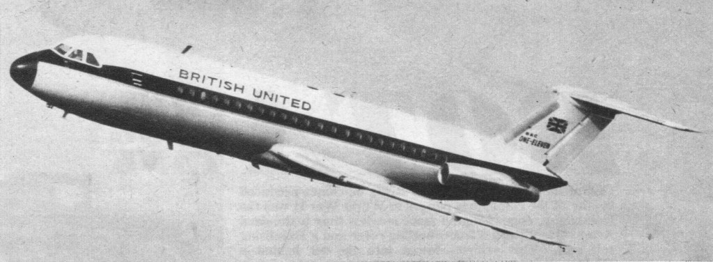
By 1957 the Hunting H.107 had been defined as a trim-looking project powered by two engines in the 6,000-lb class. But in 1960 Hunting became part of BAC (British Aircraft Corporation). By this time the design looked promising, and Vickers-Armstrongs collaborated (and eventually took over). The 107 grew into the One-Eleven, to match the thrust of the available Rolls-Royce Spey engine (10,000 lb). This made the aircraft at least a 65-seater, with 3+2 seating in a wider fuselage.
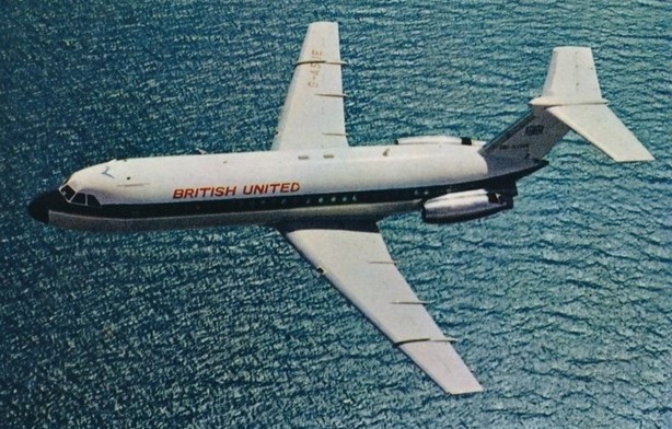
By 1961 the newly formed British Aircraft Corporation decided to proceed with the project and on the 9 May 1961 the public launch took place as the first order was announced by the company for 10 aircraft from British United Airways. On 23 October Braniff Airways placed a firm order for 6 aircraft. Other orders soon followed from Mohawk Airlines for 4 aircraft, Kuwait Airways for 3 aircraft and by Central African Airways for 2 aircraft. Braniff Airways subsequently doubled it’s order to 12 aircraft while Aer Lingus ordered 4 aircraft. Western Airways ordered 10 aircraft but later it was cancelled. The biggest breakthrough came when American Airlines ordered 15 aircraft on the 17 July 1963. 60 orders had been received by the time the first 1-11 was rolled out.
BAC 1-11 G-ASJE
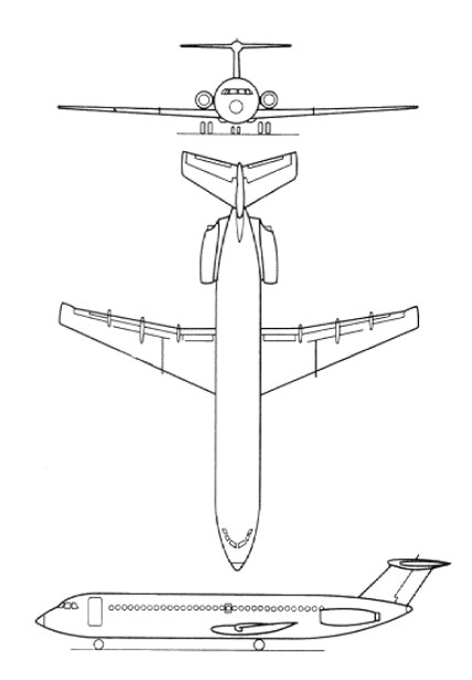
The finally revised aircraft incorporated a circular-section all-metal pressurised fuselage, low-set swept monoplane wings incorporating Fowler type trailing-edge flaps, and airbrakes/spoilers on the wing upper surface, forward of the flaps. The T-tail included a variable-incidence tailplane, and the landing gear, of hydraulically retractable tricycle type, had twin wheels on each unit. Accommodation was provided for a maximum of 79 passengers in five-abreast high-density seating, and in addition to a conventionally placed passenger door at the forward end of the cabin on the port side, the BAC.111 had also a ventral airstair below the tail unit, giving access to or from the aft end of the cabin. Powerplant of the prototype One-Eleven Series 200, which was intended as the basic production version, consisted of two 4722kg thrust Rolls-Royce Spey Mk 506 turbofans.
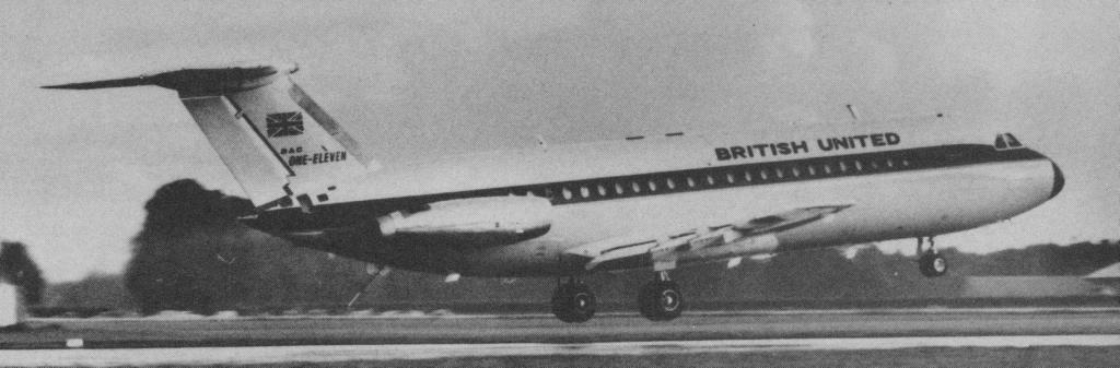
The prototype G-ASHG rolled off the Hurn production line on 28 July 1963 in the livery of first customer British United Airways. The first flight took place on 20 August 1963. G.R.Bryce, chief test pilot for BAC, conducted the 27 minute first flight from Bournemouth (Hurn) airport. Taking off in 3150 ft, and reaching 8000 ft and 220 mph, wheels and flaps were left down. The first BAC One Eleven totalled 30 hr. 30 min in the air in the 24 days following the maiden flight.
BAC 111 first take-off
This aircraft crashed on 22 October during the flight development programme, together with a highly experienced crew of seven that included test pilot M. J. Lithgow. Investigation showed the cause to be a deep stall, resulting from the T-tail and rear-mounted engine configuration, and remedial action included the installation of powered elevators, a stick-pusher, and modification of the wing leading edges. These changes were adequate to prevent the aircraft from assuming an inadvertent and dangerous angle of attack, a condition peculiar to this configuration, in which the wing loses lift and the horizontal tail surfaces are unable to restore longitudinal stability. Despite this early setback the flight test program continued and customer confidence remained high. American Airlines and Braniff Airways placed more orders in February 1964. During this year further orders were received from Mohawk Airlines, Philippine Airlines and from Helmut Horten who ordered the first Executive aircraft. After nearly 2 years of flight testing the aircraft was certified on 5 April 1965 and the first 1-11 delivery, G-ASJI to British United Airways, took place on 22 January 1965. After several weeks of route proving flights the first revenue service commenced on 9 April with G-ASJJ from Gatwick to Genoa. Braniff took delivery of their first aircraft N1543 on 11 March while Mohawk Airlines took their first aircraft on 15 May. Deliveries continued to take place and by the end of 1965 34 aircraft had been received by their customers. Such was the demand that a second production line was set up at Weybridge to cope. Total deliveries for 1966 stood at 46 aircraft. 1967 to 1971 saw another 120 aircraft delivered with the most significant order going to British European Airways. In the period 1972 until the production line finally closed in 1982 only another 35 aircraft were built.
The first version, the Series 200, weighed 73,5001b and could seat 79. This sold to Braniff and Mohawk of the USA. Long before certification, in May 1963, the British Aircraft Corporation (BAC) announced that it was intended to develop two other versions in addition to the basic Series 200. These were to include an increased payload/range One-Eleven Series 300, with 5171kg thrust Spey Mk 511 turbofans, and a generally similar One-Eleven Series 400 that would incorporate modifications to meet US requirements. As well as introducing more powerful engines, the Series 300 had increased fuel capacity, and strengthened wings and landing gear to cater for a 3856kg increase in gross weight. Interest in the One-Eleven was growing, following the initial order of 10 Series 200 aircraft from British United Airways (BUA), and market potential within the USA was demonstrated by an early order for six aircraft from Braniff International. When this was followed by orders from other US carriers, including American Airlines, the prospect for fairly large US sales seemed very good. However, by the time that FAA Type Approval was awarded, on 16 April 1965, there was a growing number of aircraft competing within the same payload/range category, and total sales to US carriers failed to reach the figures that had at one time seemed possible. Initial One-Eleven services were flown by British United, from Gatwick to Genoa, on 9 April 1965; in the USA, Braniff’s first Corpus Christi-Minneapolis revenue flight was made on 25 April. In January 1966, BUA inaugurated London-Scotland and London-Northern Ireland One-Eleven domestic routes. Production of the three initial versions of the One-Eleven totalled 134: 56 Series 200, nine Series 300, and 69 Series 400 aircraft.
The Series 300, with 11,400-lb engines, weighed 85,000 lb, with more fuel and more powerful brakes. The Series 400 was a 300 tailored to the US market, with weight reduced for two-crew operation and many special US features. American bought 30. Iit was not until British European Airways (BEA) began to show interest in an enlarged One-Eleven that design of what was to become the One-Eleven Series 500 was finalised. With a fuselage lengthened by 2.54m forward of the wing, and 1.57m aft of the wing, the Series 500 could accommodate a maximum of 119 passengers. More powerful Speys of up to 12,550-lb thrust with water injection engines were introduced, the wing span increased by 1.52m, and the structure of both landing gear and wings strengthened to make possible a significant increase in gross weight. This was originally 41277kg for takeoff, but has since been raised to a maximum of 47400kg. The prototype for the Series 500 was produced by conversion of the Series 400 development aircraft, and this flew for the first time in its new configuration on 30 June 1967. ARB certification of a production example was gained on 15 August 1968, and BEA’s first revenue flight was flown three months later, on 17 November. The final variant to appear was the One-Eleven Series 475, intended for operation from and into smaller airports, or in higher temperature/altitude environments. This retains the standard fuselage/accommodation of the Series 400, and combines the powerplant and wings of the Series 500, plus a modified landing gear with low-pressure tyres, anti-slush protection and gravel deflectors to permit operation from lower-grade surfaces. In addition to Series 475 and 500 aircraft which were available from BAe in standard configuration, two other special variants were available. These comprised executive or freighter configurations, and approximately 40 examples of the former are in service worldwide. The freighter conversion includes installation of a 3.05 by 1.85m hydraulically actuated cargo door in the port forward fuselage, and a quick-conversion freight handling system. New-technology options for new aircraft, and in some cases suitable for retrospective installation, include a fully certificated Category II automatic landing system, automatic throttle control, and engine ‘hush-kits’. The One-Eleven continued in production after BAC was merged into British Aerospace, concluding at No. 230 in July 1980. The largest order received during the last ten years came from Tarom. The last aircraft to be built was G-BLDH construction number 262. The last aircraft to be delivered was G-BLHD “Last Hurn Delivery” construction number 260. This took place on 30 May 1984. A total of 235 aircraft had been delivered from Hurn and Weybridge. In 1979 British Aerospace had concluded an agreement with CNIAR of Romania, providing for manufacture of the One-Eleven in Romania under licence. The prime contractor is IAv Bucuresti, and the deal provided for BAe to supply three complete aircraft plus 22 kits for Romanian assembly. Romania picked two variants, the 495, an upgraded 475, and the 560, an upgraded 500 with engines fitted as standard with noise suppressors. The first flight of a Rombac 1-11 YR-BRA took place on 18 September 1982. Production continued until the 9th and last ever new production 1-11 YR-BRI came off the line. It’s first flight took place in April 1989. It was delivered to Romavia in 1991. The demise of the Rombac project came about due to the unstable political situation in Romania. Total production of the BAC 1-11 therefore was 244 aircraft. 2 further airframes remained incomplete in Romania. These consisted of several models. The series 200, 300, 400, 475, 500, 670. In February 1986 Dee Howard of the USA announced agreements with Rolls-Royce and British Aerospace for retrofitting One Elevens with the Tay 650 engine. Shown at Farnborough 1990 by Aeritalia was the first Dee Howard BAC One-Eleven conversion powered by two Rolls-Royce Tay 650 turbofans, each rated at 15,100 lb st (67,17 kN). Available for Series 400, 475 and 500 aircraft, the conversion involves replacing the original Speys with the new engine, new nacelles and Dee Howard-developed thrust reversers which will enable the aircraft to meet FAR Pt 36 Stage 3 noise requirements as well as other, more restrictive, local regulations. The first conversion, called the BAC-1-11/2400, first flew on 2 July 1989. The only operational aircraft to survive in the UK in 2002 were the 3 aircraft operated by QinietQ, ZE432, ZE433 and ZH763, based at Boscombe Down.
BAC 111-200 Srs Powerplant: two Rolls-Royce Spey Mk 506-14, 10,410 lb thrust take-off power Wingspan, 88 ft 6 in Length, 93 ft 6 in Height, 24 ft 6 in Gross wing area, 980 sq.ft Max. usable floor area, 520 sq.ft approx Max usable volume, 3542 cu.ft Max. cabin length, 56 ft 10 in Max. width, 124 in Max. height, 78 in Accommodation: 79 passengers at 33 in min. pitch Baggage and freight hold volume: 534 cu.ft Basic operational (gross less usable fuel and payload), 46,312 lb Total fuel, 17,920 lb Max. take-off, 78,500 lb Max. landing, 69,000 lb Max. payload (volume limited), 17,688 lb Max. zero fuel, 64,000 lb Power loading (max. take-off weight), 3.77 lb/lb thrust Wing loading (max. take-off weight), 80.1 lb/sq.ft Wing loading (max. landing weight), 70.4 lb/sq.ft High-speed cruise, Mach 0.78 at 25,000 ft Long-range cruise, Mach 0.70 at 35,000 ft Approach speed, 119 kt Take-off field length ISA at sea level, 7070 ft Landing field length, ISA at sea level, 5300 ft Range with allowances, max. fuel, 14,560 lb payload, 1570 nm
BAC-1-11/2400 / Dee Howard conversion Engines: 2 x Rolls-Royce Tay 650 turbofans, 15,100 lb st (67,17 kN).
Super 111 Engines 2 x 11,970 lb. (5,434 kg.) thrust Rolls Royce Spey turbofan. Length 107 ft. (32.61 m.) Wing span 93.5 ft. (28.5 m.) Weight empty 53,995 lb. (24,490 kg.) Max. capacity: 99 passengers Max cruise 548 m.p.h. (882 km.p.h.) Max cruise alt: 35,000 ft. (10,670 m.) Range 576 miles (927 km.) with typical payload/2 hr res.
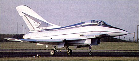
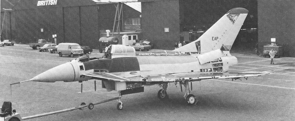
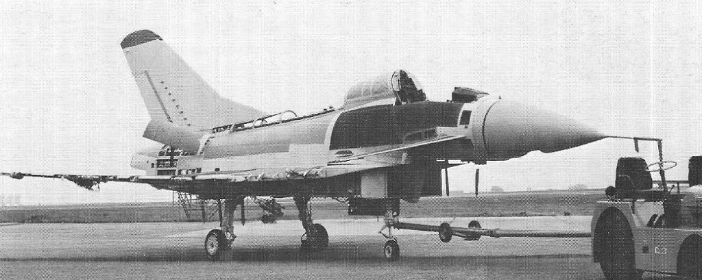
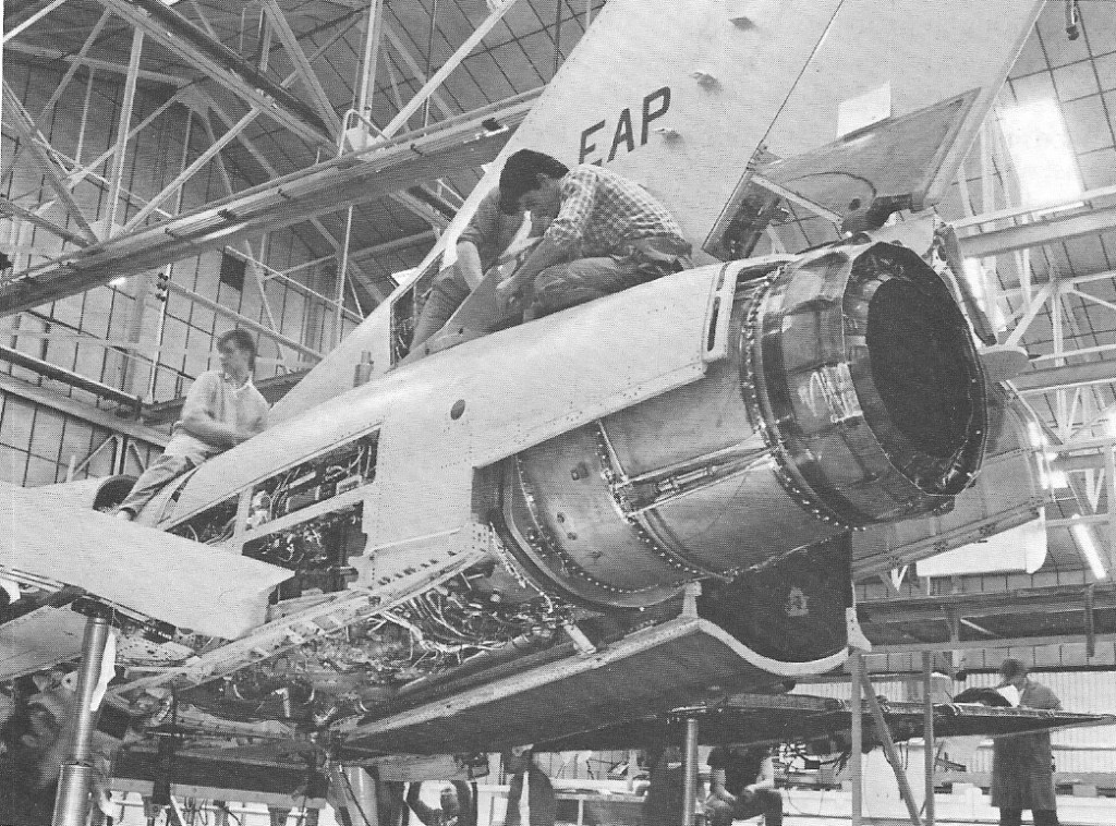
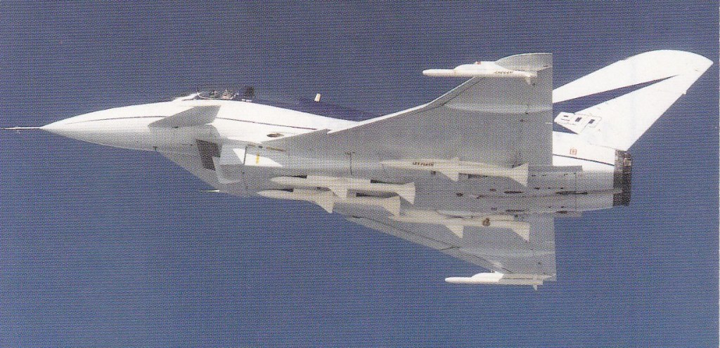
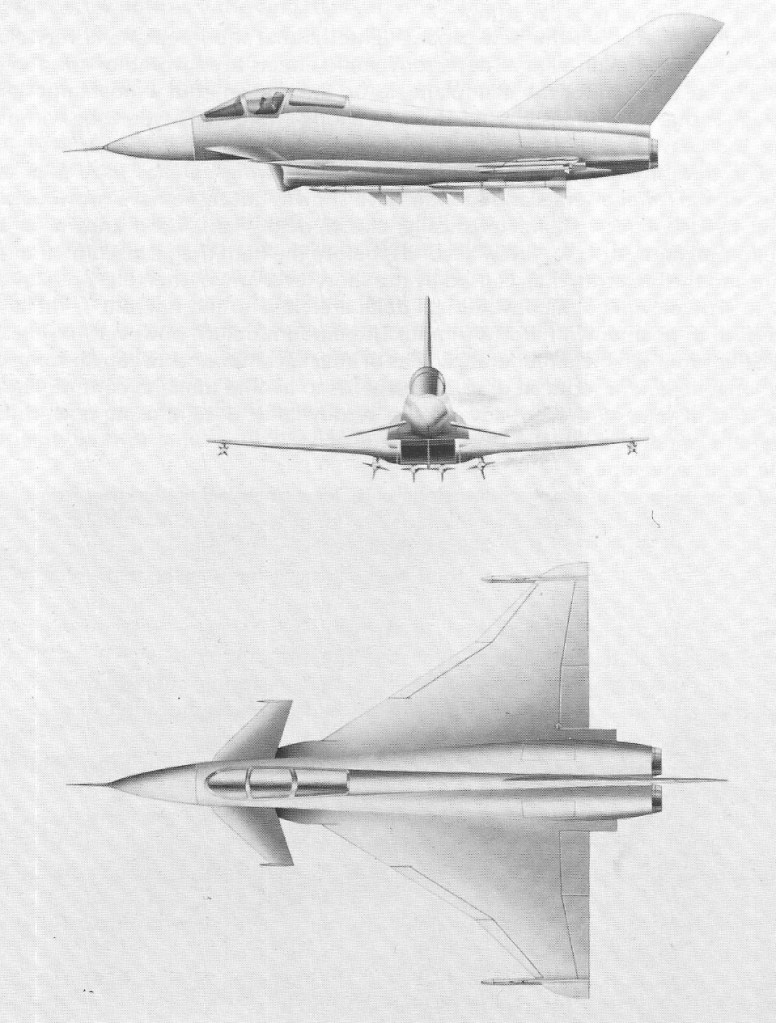
EAP is a single-seat aircraft with a compound-sweep delta wing and an all-moving canard. Power is provided by twin reheated RB.199 turbofans fed by chin intakes. The contract for the design, development, and construction of the demonstrator was signed in May 1983.
Prototype EAP October 1985
Prototype EAP October 1985
The EAP technology demonstrator aircraft exceeded Mach 1.1 on its first flight on August 8, 1986. Produced by British Aerospace in collaboration with several industrial partners, including Aeritalia, MBB, Rolls-Royce, Dowty, Ferranti, and GEC, the EAP has received financial support from the UK Government. Intended to demonstrate a complete weapons system for the 1990s, the EAP incorporates many advanced-technology features, including the extensive use of carbon-fibre structures, advanced aerodynamics, digital fly-by-wire with relaxed stability, a digital databus, and an integrated electronic cockpit.
EAP Engines: 2 x Turbo-Union RB 199-34R Mk, 40.0-75.7kN Take-off weight: 14515 kg / 32000 lb Empty weight: 10000 kg / 22046 lb Wingspan: 11.77 m / 38 ft 7 in Length: 17.72 m / 58 ft 2 in Height: 5.70 m / 18 ft 8 in Wing area: 51.66 sq.m / 556.06 sq ft Max. speed: 2M Crew: 1
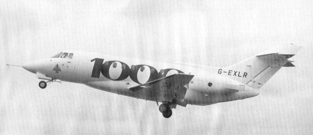
British Aerospace’s new BAe 1000, derived from the BAe 125 800, made its first flight in June 1990 from Chester. The BAe 1000 is billed as an intercontinental range, mid sized, corporate jet. The most obvious visual difference compared with the 125 Srs 800 is the lengthened fuselage with a more prominent external ventral fairing containing more fuel, stretched in size (84cm) as well as range (by 21 percent to 3635 nm). The cabin is deeper and there is space for a maximum of 15 in high density seating.
Engines: 2 x Pratt & Whitney Canada PW305 turbofans, 5,200 lb st (23,13 kN).
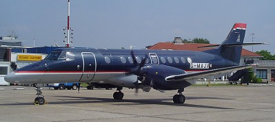
Development work on the Jetstream 41 was announced in mid-1989. A stretched development of the Jetstream 31/32 regional aircraft family by BAE Systems, the J41’s structural changes included an increase of 4.88m in length of the semi-monocoque aluminium alloy fuselage. The fuselage stretch is througha 2.51-m forward plug and a 2.36-m stretch behind the wing. The increase in length allows for 29 passenger seats, compared with the 19 typically fitted to the J31. The wingspan has been increased to 18.29 m, the ailerons and flaps have been reworked, and the entire wing has been mounted lower on the fuselage to remove the spar from the interior cabin floor. This led to a redesign of the engine mounts to increase ground clearance for the McCauley propellers, and the distance between the fuselage and the engines has also been increased. As a result, the cabin is quieter than the J31. The fuel system consists of two integral wing tanks and has the capacity for 5,818 lb (2,639 kg) of Jet Al. Both the main undercarriage and the nose gear are forward retracting and are fitted with twin wheels. Anti-skid three-rotor steel brakes are also installed.
The J41 is designed to operate to and from runways as short as 1219m. The aircraft can operate from a runway at 5,000 ft elevation at temperatures of ISA +20 with a full load for at least a one-hour sector with IFR reserves. Four “glass” screens of the Honeywell EDZ-805 EFIS (electronic flight instrument system) grace the cockpit and the flight deck instrumentation also includes a Honeywell SPZ-4500 fully digital automatic flight control system with an AH-600 attitude and heading reference system (AHRS), an AZ-810 air data computer and a Honeywell Primus II digital radio communications system with dual transponders. The J41 first flew on 25 September 1991 and 104 J41 aircraft were built before production was terminated in May 1997. Over 90 Jetstream 41s world¬wide remained operational in 2003.
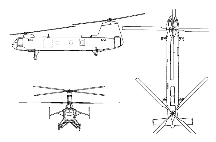
Undertaken by Bristol in response to Royal Navy and Canadian naval specifications were the models 191 and 193.
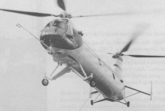
The Bristol 191 was a ship-based development of Type 173 with modified fuselage, u/c etc.
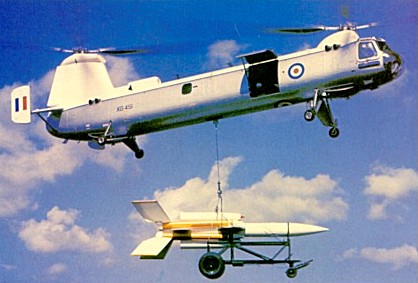
The Bristol 192 was the production version of Model 191 for RAF use with two cabin windows only, starboard cargo hatch, cargo hoist beneath fuselage, large anhedralled tailplane and powered by two 1465shp Napier Gazelle 2 turboshafts, derated to 920shp. In the initial configuration, the 192 had a purely manual system of control and wooden rotor blades but power controls and metal blades were standardized on the fifth prototype built in 1960. The prototype Type 192 (XG447) first flying on 5 July 1958 at Westonsuper-Mare, was demonstrated at the Farnborough air show in September 1952. That year, three pre-production aircraft were assigned to the RAF for a series of trials for which they were based at Odiham.
As the Westland Belvedere this entered service with the Royal Air Force, though this was only after the 191 and 193 had been cancelled by the RAF and Royal Canadian Air Force respectively.
Twenty-six of these helicopters were ordered and used for some years for military transport, not only in the United Kingdom, but also in the Middle and Far East. The Belvedere was withdrawn from service in March 1969.
The production Bristol 192s had an all-metal, skinned fuselage and an anhedral tailplane, compared with the dihedral one of the Type 173. The two rotors had four metal blades and the front wheels of the fixed quadricycle landing gear were self-castoring. The helicopter’s maximum capacity was 30 seats or 2700kg internal payload. The instrumentation also permitted night flying.
As the 192C it was tested by BEA and offered its 24 passengers a unique high-speed service between London and Paris. British European Airways leased a Belvedere briefly but never used it in commercial service.
On May 30, 1961, C T D Hosegood flew from London to Paris in 1 hour 41 min 28 sec and on June 2, 1961, from Paris to London in 1 hour 40 mm 55 sec. This is the equivalent of 202.32km/h outwards and 203.51 km/h on the return flight.
Bristol B 192 Belvedere HC Mk I Engines: 2 x Napier Gazelle 2, 1627 shp, 1092kW Fuselage length: 54.134 ft / 16.5 m Length with rotors turning: 27.36m Height: 17.388 ft / 5.3 m Rotor diameter: 48.885 ft / 14.91 m Max take off weight: 18522.0 lbs / 8400.0 kg Empty weight: 5277kg Max. speed: 119 kts / 220 km/h Service ceiling: 13123 ft / 4000 m Range: 378 nm / 700 km Crew: 2 + 25 PAX / 2700kg