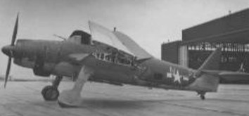
AILE PX-2000

Single seat single engined high wing monoplane with conventional three axis control. Wing has swept back leading and trailing edges, and constant chord; cruciform tail. Pitch control by elevator on tail; yaw control by fin mounted rudder; roll control by fullspan ailerons; control inputs through stick for pitch/roll and pedals for yaw. Wing braced from above by kingpost and cables, from below by cables and struts; wing profile Clark Y; double surface. Undercarriage has three wheels in tricycle formation with additional tailskid; rubber suspension on nosewheel and steel spring suspension on main wheels. Push-right go right nosewheel steering connected to yaw control. Optional brakes on main wheels. Aluminium tube framework, partially enclosed. Engine mounted above wing driving tractor propeller.
The PX2000 design studies began in December 1982 following an idea of Patrick Lemonnier. The construction of the prototype was begun in February 1983 and it made its first flight on the 3 April. Its test programme included as much static testing as flight testing, static tests being entrusted to Ingenerie Technique Atlantique (ITA), a specialist aeronautical and marine laboratory.
By 1982 the single seater had already largely confirmed the calculated performance figures. The figures quoted below correspond to the prototype which is fitted with a Fuji Robin EC44 2PM, hand started and developing 43 hp. It was tested without the glass fibre pod with polycarbonate windscreen, and the three wheel fairings which will be fitted to the production models.

Engine: Robin EC442PM, 53 hp at 6750 rpm
Prop¬eller diameter 65 inch, 1.64m
Toothed belt reduction, ratio 2.5/1
Max static thrust 309 lb, 140 kg
Power per unit, area 0.39hp/sq.ft, 4.2 hp/sq.m
Fuel capacity 1.8 US gal, 6.6 Imp gal, 30.0 litre
Length overall 17.5 ft, 5. 30 m
Height overall 7.9ft, 2.40m
Wing span 29.9ft, 9.10m
Chord at root 4.3ft, 1.29 m
Chord at tip 2.7ft, 0.82m
Dihedral 2 deg
Sweepback 5 deg
Tailplane span 8.7 ft, 2.61 m
Fin height 3.9 ft, 1.20 m
Total wing area 136 sq.ft, 12.6 sq.m
Total aileron area 31.5 sq.ft, 2.92 sq.m
Fin area 9.1 sq.ft, 0.85 sq.m
Rudder area 7.5 sq.ft, 0.70 sq.m
Tail¬plane area 12.7sq.ft, 1.18 sq.m
Total elevator area 10.3 sq.ft, 0.96 sq.m
Wing aspect ratio 6.59/1
Wheel track 4.7 ft, 1.40 m
Wheelbase 4.7 ft, 1.40 m
Nosewheel diameter overall 10 inch, 25 cm
Main wheels diameter overall 12 inch, 30cm
Empty weight 3091b, 140kg
Max take off weight 574 lb, 260kg
Payload 265 lb, 120kg
Max wing loading 4.24 lb/sq.ft, 20.7 kg/sq.m
Max power loading 10.83 lb/hp, 4.9kg/hp
Load factors; +6.0, 4.0 ultimate
Max level speed 87mph, 140kph
Never exceed speed 106mph, 170kph
Max cruising speed 81mph, 130kph
Economic cruising speed 65mph, 105kph
Stalling speed 22mph, 35kph
Max climb rate at sea level 1000ft/min, 5.1m/s
Min sink rate 400fpm at 34 mph, 2.0 m/s at 55 kph
Best glide ratio with power off 10/1 at 37mph, 60kph
Take off distance 115 ft, 35 m
Landing distance 131 ft, 40 m
Service ceiling 10,000 ft, 3050 m
Range at average cruising speed 218 mile, 350km
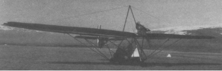
AILE Patrilor 3

Side by side two seat single engined high¬wing monoplane with conventional three axis control. Wing has swept back leading edge, swept forward trailing edge and tapering chord; cruciform tail. Pitch control by elevator on tail; yaw control by fully flying rudder; roll control by ailerons; control inputs through stick for pitch/roll and pedals for yaw. Wing braced from above by kingpost and cables, from below by struts; wing profile double surface. Undercarriage has three wheels in tricycle formation; no suspension on any wheels. Push right go right nosewheel steering connected to yaw control. No brakes. Aluminium tube framework, with optional pod. Engine mounted above wing driving tractor propeller.
A Patrick Lemonnier design, the Patrilor 3 two seater was assembled without any prior engineering drawings, in his automotive repair and panel beating shop.
Prototype 01 made its first flight at the end of May 1982 and was shown at the end of July at the Brienne amateur constructors’ convention. Number 02 then appeared but prematurely terminated its career with a dicey landing and was followed by a number 03, which successfully completed the first London to Paris in the hands of Jacques Toulorge.
Production models have been on sale since November 1982 and have met with exception¬al success. The company, in April 1983, added to this strut braced machine a kingpost and landing wires, which give increased structural integrity and which have the secondary effect of improving aileron efficiency by stiffening the wing. This machine is therefore now one of those rare aircraft which use two struts in a V to support each wing plus wires stiffening it from above.
In standard form the Patrilor 3 is delivered built and tested by the manufacturer. It is deriggable by one person in 20 min and trailer transportable. The folded dimensions are 21.8 x 6.2 x 8. 0 ft (6.60 x 1. 88 x 2.45 m). Options include a fairing for the forward part of the framework (made of transparent polycarbonate), dual controls, carburettor heat kit, plus an instrument panel with basic instruments. Additionally, the standard Hirth engine can be replaced by the Robin EC44 2PM of 53 hp. Planned is a second model, the Patrilor 3bis with flaps, and a crop spraying version named Agrilor. For North America, Patrilors are delivered as kits and the 40 h building time is the responsibility of the dealer.

Engine: Hirth 2701R, 43 hp at 6750 rprn
Propeller diameter 56 inch, 1.42 m
Toothed belt reduction, ratio 2.5/1
Max static thrust 254 lb, 115 kg
Power per unit area 0.18hp/sq.ft, 2.0hp/sq.m
Fuel capacity 8.5 US gal, 7.0 Imp gal, 32.0 litre
Length overall 19.4 ft, 5.90 m
Height overall 8.0ft, 2.45m
Wing span 38.7ft, 11.75m
Chord at root 5.5ft, 1.64m
Chord at tip 3.5ft, 1.05m
Dihedral 3 deg
Sweepback 8deg
Tailplane span 11.1 ft, 3.38 m
Total wing area 233 sq.ft, 21.6 sq.m
Total aileron area 17.2 sq.ft, 1.60 sq.m
Rudder area 8.2 sq.ft, 0.76 sq.m
Tail¬plane area 17.2 sq.ft, 1.60sq.m
Total elevator area 11.8sq.ft, 1.10 sq.m
Wing aspect ratio 6.4/1
Wheel track 5.6ft, 1.72m
Wheelbase 6.2ft, 1.88m
Tailwheel diameter overall 10 inch, 25 cm
Main wheels diameter overall 16 inch, 40 cm
Empty weight 320 lb, 145 kg
Max take off weight 707 lb, 320 kg
Payload 387 lb, 175 kg
Max wing loading 3.03 lb/sq.ft, 14.8 kg/sq.m
Max power loading 16.4 lb/hp, 7.4 kg/hp
Load factors; +4.5, 3.8 ultimate
Max level speed 56 mph, 90 kph
Never exceed speed 68 mph, 110 kph
Max cruising speed 50 mph, 80 kph
Economic cruising speed 43mph, 70kph
Stalling speed 22 mph, 35 kph
Max climb rate at sea level 500 ft/min, 2.5 m/s
Min sink rate 600 fpm @ 24 mph, 3.0 m/s @ 40 kph
Best glide ratio with power off 8/1 at 37 mph, 60 kph
Take off distance 115 ft, 35 m
Land¬ing distance 115 ft, 35 m
Service ceiling 10,000ft, 3050 m
Range at average cruising speed 125 mile, 200 km

Aichi M6A Seiran

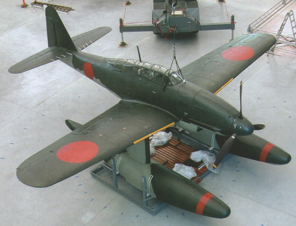
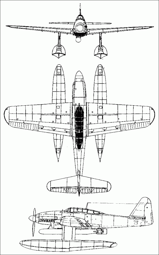
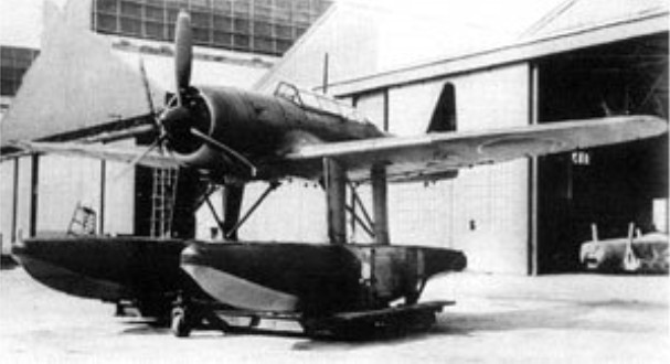
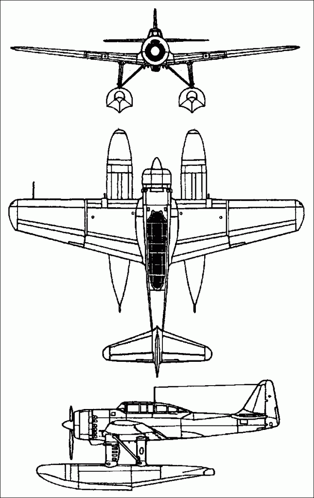
The Aichi M6A-1 Seiran attack floatplane was to be housed in water-tight containers and released from Japanese Navy I-400 class submarines. The wings rotated back and folded flat against the fuselage. Part of the horizontal and vertical stabiliser also folded.

The first prototype flew in November 1943 and a total of 28 were built. The design was in full production in 1945, with the aircraft and its submarine counterparts being readied for an attack on the Panama Canal when the war ended.

The Aichi M6A Seiran (translated as “Mountain Haze”) was a single engine design, powered by a Atsuta 32 inline piston engine of 1,400 horsepower driving a three-blade propeller. Crew accommodations amounted to one personnel and standard armament is known to consist of a single 500lb bomb, mounted under the fuselage presumably. Design of the aircraft consisted of a low-monoplane type with a single rudder aft. The cockpit was situated at center above the wing roots.

At the end of May 1945, at the instigation of Admiral Yamamoto, a series of I-400 submarines were ordered, each able to carry three special duty aircraft. A catapult stretched from the cylinder hangers in the starboard hold, forward to the bow.

The aircraft were twin seater Aichi M6A1 Seiran seaplanes specially designed for a bombing raid on the Panama Canal. The Seirans were powered by German Daimler-Benz DB601A of 1400 hp.
They were designed to drop off the crew after the raid, be ditched beside the submarine and sink at once.
On 25 June 1945 the plan was halted.

On 25 June 1945, Imperial Japanese Headquarters halted preparations for the Japanese 1st Submarine Flotilla to attack the Panama Canal, and issued new orders: In view of the American threat to the main Japanese islands, the 12 Seiran aircraft were ordered to find a suitable opportunity to launch a kamikaze raid (operation Hikari) against US aircraft carrier, but the surrender came before the operation could be carried out.

A land-based derivative known as the M6A1K “Seiran Kai” was utilized for pilot training purposes. Landing gear was of the standard two-front with a tail wheel at rear for this land-based variant.

Aichi M6A1 Seiran
Engine: 1 x Aichi Atsuta Type 32 inline radial, 1,400hp.
Wingspan: 12.26 m / 40 ft 3 in
Length: 11.64 m / 38 ft 2 in
Height: 4.58 m / 15 ft 0 in
Wing Area: 27.0 sq.m / 290.63 sq ft
Take-Off Weight: 4040-4445 kg / 8907 – 9800 lb
Empty Weight: 3300 kg / 7275 lb
Maximum Speed: 295mph (474kmh; 256kts)
Cruise Speed: 300 km/h / 186 mph
Maximum Range: 1,243miles (2,000km)
Service Ceiling: 32,480ft (9,900m)
Armament: 1 x 13mm machine-gun, 850-kg torpedo or 1 x 800-kg bomb or 2 x 250-kg bombs
Crew: 2
Hardpoints: 1

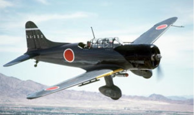
Aichi D3A

Aichi (along with Nakajima and Mitsubishi) submitted their monoplane design designed by a team under Tokuhishiro Goake to a 1936 Japanese Navy specification (11-Shi) for a carrier-based dive-bomber to replace the aging D1A biplane series. Only Aichi’s and Nakajima’s submissions were pressed for further development with the request for a full working prototype.

Aichi D3A Val Article

The initial prototype was completed in December of 1937 and first flew in 1938 and fitted with Nakajima Hikari 530kW / 710 horsepower engines. Despite a poor showing, a second improved prototype was made in an attempt to address issues in stability, strength and power. The second prototype was selected for production over the Nakajima model.

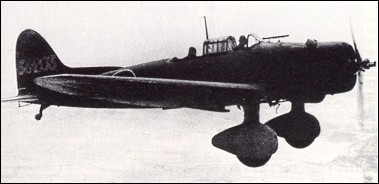
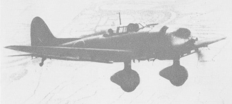
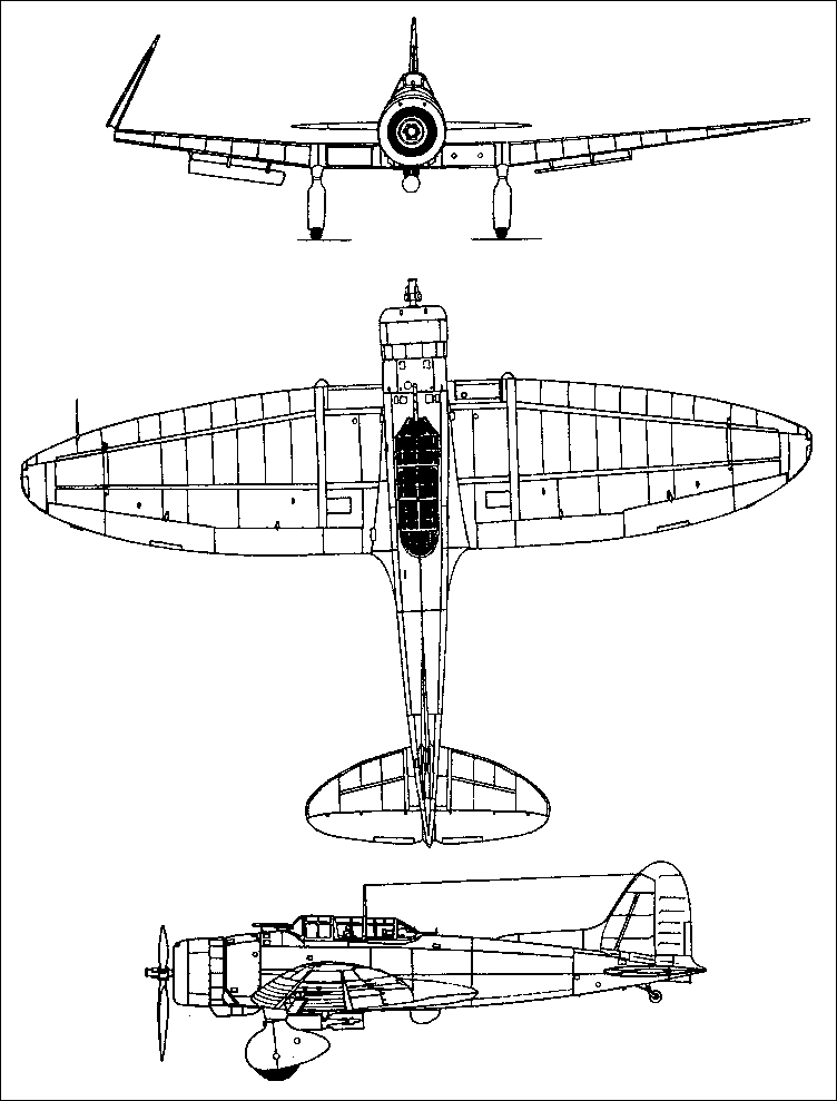
Production D3A1 aircraft features included slightly smaller elliptical wings, with narrow dive brakes and carrying spatted landing gears, a 1000 hp / 745kW Mitsubishi Kinsei 43 radial in a redesigned cowling, tandem cockpits under transparent canopies, one movable and two fixed machine guns, and normal bombload of one 250 kg (551 lb) weapon on swinging arms, plus two 60 kg (132 lb) under the outer wings. A dorsal fin extension considerably improved the aircraft’s manoeuvrability. Carrier trials were flown in August 1940, and substantial numbers of D3Als were operational from land bases in China and Indo China from October 1940.

Standard armament of production models was 3 x 7.7mm machine guns. Two Type 97 Light Machine Guns were fixed to fire forward and controlled by the pilot while a single Type 92 Heavy Machine Gun was fitted in a flexible mount in the rear cockpit.

Early “Vals” were flown in limited land-based operations in the Indo-China theatre though the rest of the war would see them operating in unison with her Imperial Japanese Navy carrier-based counterparts. The D3A series of aircraft (code named “Val” by the Allies) were thought to be all but extinct when the war in the Pacific began. The awakening came in the form of the surprise attack on Pearl Harbour as D3A’s made up the principle attack air arm in that assault.

At Pearl Harbor, 126 aircraft dive bombed targets with great accuracy, and were the only type in the first wave of attackers. Subsequently the D3A1, or Type 99 carrier based bomber Model 11, was in the forefront of Pacific battles, receiving the Allied code name ‘Val’. In April 1942 a very small force sank the cruisers HMS Dorsetshire and Cornwall and the carrier Hermes, achieving direct hits with more than four bombs out of five. But in the battles of the Coral Sea, off Guadalcanal, Santa Cruz and the Solomons, both the D3A1 and the Japanese aircraft carriers suffered such crippling losses and forced withdrawal by most of the survivors to land bases.

In June 1942 production of the D3A1 ended after 478 were built, replaced by the more powerful and better streamlined D3A2 with 1300 hp Kinsei 54, and increased fuel capacity.

D3A2

Aichi built a total of 816 of this model, the Type 99 Model 22, by June 1944, and Showa also built 201 by the end of the war. Like all Japanese warplanes of the post 1942 period, the D3A2 had no chance. Nearly all operated from land airstrips, suffered severe losses and accom¬plished little. By mid 1944 most were in use as trainers (D3A2 K), but large numbers were then reassigned to front line duty in the Kamikaze role focusing in and around the areas of Leyte and Okinawa during the final year of the war.

Production amounted to 476 D3Als and 1,016 D3A2. The Allied reporting name was ‘Val’.

D3As would end up being responsible for the destruction of more Allied shipping vessels than any other Axis aircraft during the war.

Prototype
Nakajima Hikari 1 Radial, 530kW

D3A1
Engine: Kinsei 44, 1075 hp

D3A1
Engine: 1 x Mitsubishi Kensei-53, 750kW
Wingspan: 14.36 m / 47 ft 1 in
Length: 10.20 m / 33 ft 6 in
Height: 3.85 m / 12 ft 8 in
Wing area: 34.9 sq.m / 375.66 sq ft
Take-off weight: 3650 kg / 8047 lb
Empty weight: 2408 kg / 5309 lb
Max. speed: 385 km/h / 239 mph
Cruise speed: 295 km/h / 183 mph
Ceiling: 9300 m / 30500 ft
Range: 1500 km / 932 miles
Crew: 2
Armament: 3 x 7.7mm machine-guns, 1 x 250-kg bomb, 2 x 60-kg bombs

D3A2
Engine: 1 x Mitsubishi Kinsei 54 radial, 1,300 horsepower.
Span: 14.365 m / 47 ft 1.5in
Length: 10.195 m / 33 ft 5.5 in
Height: 12.63ft (3.85m)
Gross weight: 3800 kg / 8377 lb
Empty Weight: 2,570kg / 5,666 lb
Maximum speed: 430 km/h (267 mph / 232kt) at 18,536 ft
Maximum Range: 840miles (1,352km)
Rate-of-Climb: 1,640ft/min (500m/min)
Service Ceiling: 34,449ft (10,500m)
Max range: 970 mi
Bombload; 816 lb
Armament: 2 x 7.7mm fixed forward-firing machine guns
1 x 7.7mm trainable machine gun in rear cockpit position.
Bombload: 1 x 551lb bomb under-fuselage OR 2 x 132lb bombs under wings
Accommodation: 2
Hardpoints: 3

D3A
Engine: 1 x Mitsubishi Kinsei, 1,045 hp
Length: 34.75 ft / 10.57 m
Wing span: 47.7 ft / 14.53 m
Weight empty: 5,770 lb / 2,617 kg
Max speed: 270 mph / 430 kph
Range: 840 miles / 1,350 km
Crew: 1 pilot and 1 gunner
Armament: 2 x mg
Bomb load: 550 lb / 250 kg

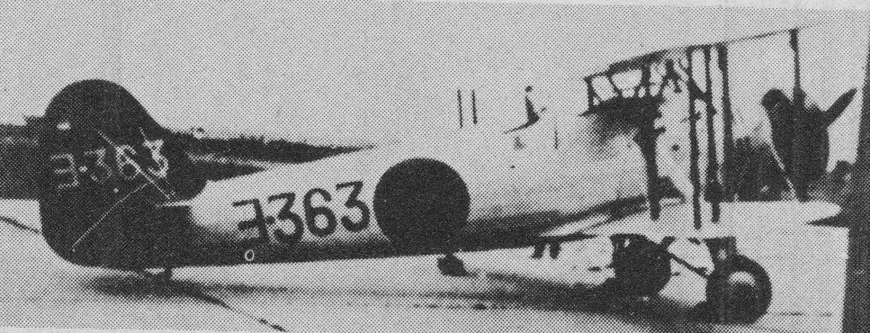
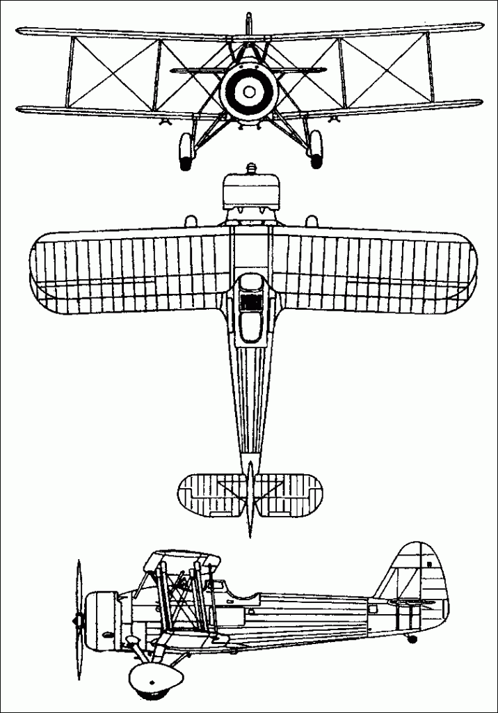
Aichi D1A

Aichi Tokei Denki Kabushiki Kaisha, which was to become a significant aircraft design and construction company during World War II, had been established in Japan during 1899 as a manufacturer of electrical equipment and watches.

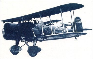
Aichi established a working relationship with Ernst Heinkel Flugzeugwerke in Germany and wishing to contend in early 1931 for an Imperial Japanese navy requirement for a two-seat carrier-based dive-bomber, requested Heinkel to design and build an aircraft to meet the navy’s specification. Required for operation with float or wheel landing gear, the resulting Heinkel He 50 prototype flew in the summer of 1931 with twin floats. A second version, with wheel landing gear, was supplied to Aichi under the export designation He 66.

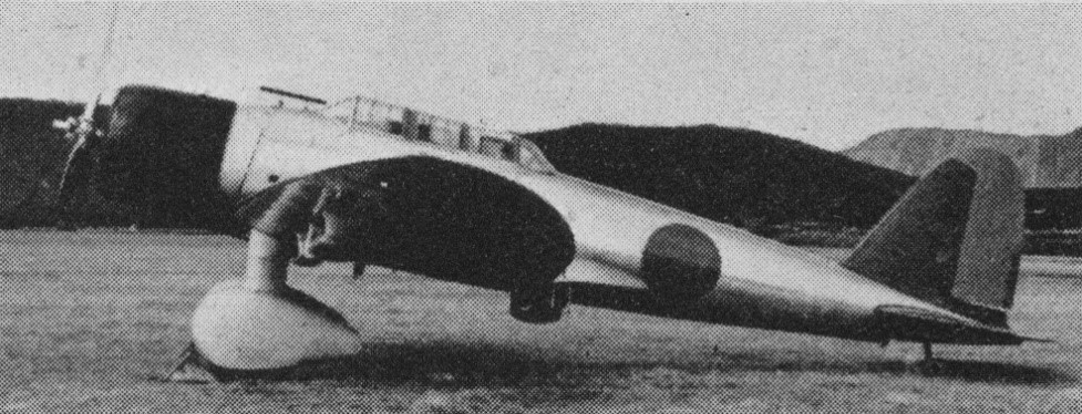
The He 66 was a two-bay biplane of metal construction with metal and fabric covering. The braced tail unit was conventional, and landing gear of fixed tailskid type. As supplied it was powered by a 365kW Siemens SAM-22B (Jupiter VI) radial engine. Modifications carried out by Aichi included strengthening of the landing gear, and installation of a 418kW/580 hp Nakajima Kotobuki 2 Kai 1 radial engine. In this form the Aichi Special Bomber was successful in trials against competing prototypes from Nakajima and Yokosuka, and was ordered into production as the Navy Type 94 Carrier Bomber (Aichi D1A1) in 1934. By 1937 162 production aircraft built, had the radial engine enclosed by a Townend ring, and other modifications included the introduction of slightly swept wings, and replacement of the tailskid by a non-castoring tailwheel. The last 44 had 433kW Kotobuki 3 engines.

Aichi’s design team under Goake created an improved D1A2 with 730¬hp Nakajima, Hikaru 1 engine in a full length NACA cowl, spats and improved windshields. Production of this version totalled 428.

Aichi D1A2

The first A2 flew late in 1936 and by 1940 Aichi had delivered no fewer than 428 as Type 96 carrier bombers. Most saw action in China, one unit dive bombing and sinking the US gunboat Panay in the Yangtze in 1937.
Only a small number of D1A1s remained in use with training units at the time of Japan’s attack on Pearl Harbor, on 7 December 1941. By December 1941 only 68 D1A2s were the serving in second-line units, and these were allocated the Allied codename ‘Susie’.

D1A1
Engine: Nakajima Kotobuki 2 Kai 19 cylinder radial 580 hp
Span: 11.4 m / 37 ft 4.75 in
Length: 9.3 m / 30 ft 6 in
Armament: two synchronized 7.7 mm (0.303 in) Type 92 machine guns, one 7.7 mm (0.303 in) Type 92 machine gun in the rear cockpit. 1 x 250 kg (551 lb) bomb under fuselage, 2 x 30 kg (66 lb) bombs under wings.

D1A2
Engine: 1 x Nakadjima “Hikari 1”, 545kW
Wingspan: 11.1 m / 36 ft 5 in
Length: 9.3 m / 30 ft 6 in
Height: 3.41 m / 11 ft 2 in
Wing area: 34.7 sq.m / 373.51 sq ft
Take-off weight: 2610 kg / 5754 lb
Empty weight: 1516 kg / 3342 lb
Max. speed: 310 km/h / 193 mph
Ceiling: 6800 m / 22300 ft
Range: 930 km / 578 miles
Crew: 2
Armament: 3 x 7.7mm machine-guns, 1 x 250-kg bomb, 2 x 30-kg bombs

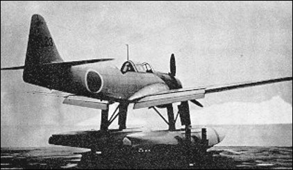
Aichi E16A Zuiun

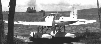
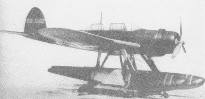
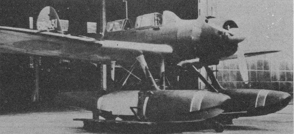
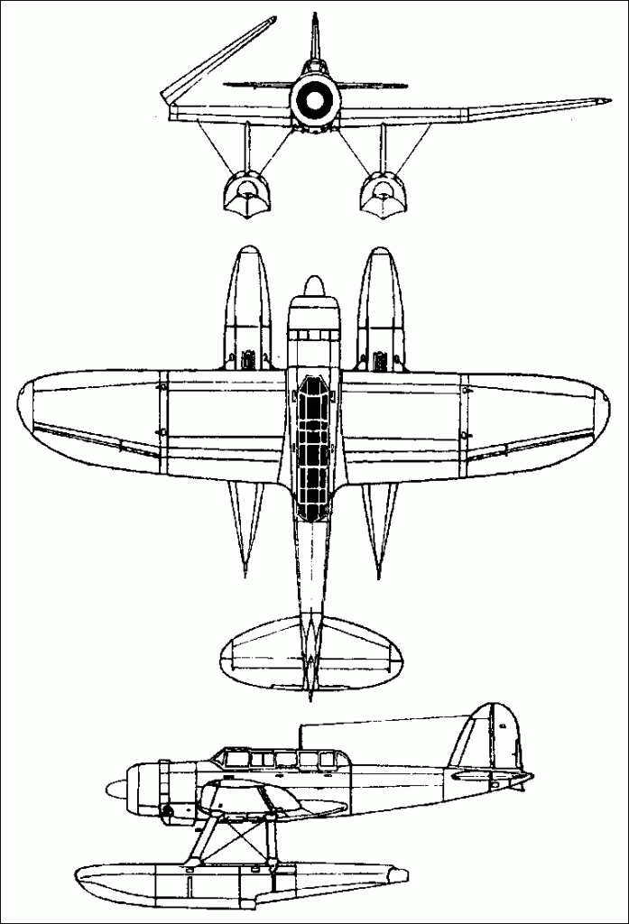
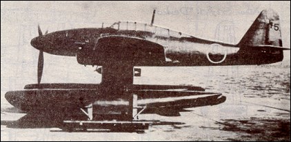
The E16A (“Auspicious Cloud”) floatplane was devised as a direct successor to the E13A “Jake” series. The E16A has crew accommodations for a pilot and a rear-cockpit gunner. Pontoons were fitted underside in place of traditional landing gears. Standard armament was 2 x 20mm forward-fixed cannons in the wings and a single 7.7mm machine gun for the rear gunner. An under fuselage position was utilized for strike runs, though the primary use of the aircraft was of carrier-based reconnaissance.

The first prototype flew in 1942, entering service in 1943, and first saw service during the Philllipines campaign. The E16A was intended as a reconnaissance type, but was often used as a ground attack aircraft and dive bomber. Allied code named ‘Paul’.

E16A1

The Aichi E16A was powered by a single Mitsubishi three-blade MK8D Kinsei 54 14-cylinder radial piston engine and could achieve a service ceiling of nearly 33,000 feet while reaching speeds of over 270 miles per hour. 256 total examples of the E16A were ever produced and of only made up of the single E16A-1 model designation.

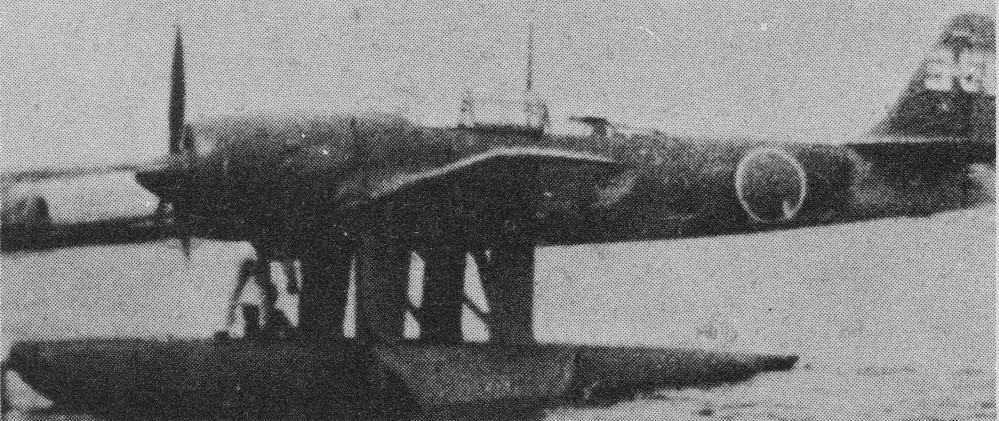
Aichi E13A1 / Watanabe E13A

E13A1

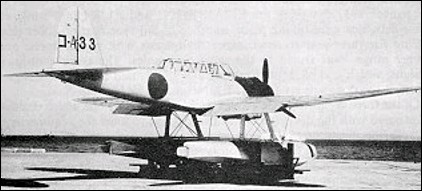
A naval staff specification issued to Aichi, Kawanishi and Nakajima in 1937 for a three-seat reconnaissance seaplane to replace the six-year-old Kawanishi E7K2 float biplane resulted in the Aichi E13A monoplane (of which 1,418 were produced). A prototype was completed late in 1938 and after competitive trials with the Kawanishi E13K in December 1940 was ordered into production as the Navy Type 0 Reconnaissance Seaplane Model 1.

The E13A was a three-crew low-wing monoplane aircraft with pontoons fitted in place of traditional landing gear systems.

Japanese cruisers and seaplane tenders carried the first aircraft from 1941, carrying a single 250kg bomb. The E13 flew a series of raids on the Hankow-Canton railway and soon afterwards E13A1 floatplanes accompanied the Japanese 8th Cruiser Division for reconnaissance patrols during the strike against Pearl Harbour in December 1941.

Though limited in number at first, the E13A series made some initial carrier-based land-strikes and reconnaissance missions that promoted the use of this aircraft type. As such, the floatplane would be fielded regularly with future cruiser groups and mounted to catapults on Japanese battleships. Standard armament would consist of 1 x 20mm downward-firing cannon and a single 7.7mm machine gun in the rear cockpit. External stores were limited to a single 551lb bomb or depth charge as needed.

As production switched to Kyushu Hikoki KK at Zasshonokuma and accelerated, the seaplanes (codenamed ‘Jake’ by the Allies) were embarked in the battleships and cruisers of the Kantais (fleets), including the battleship Haruna and cruisers Chikuma and Tone of Vice Admiral Nagumo’s Carrier Striking Force at the Battle of Midway.

In all, it is estimated that by mid-1943 more than 250 E13A1s were at sea aboard Japanese ships.

The Aichi E13A would serve through to the end of the war, though limited by the power of the new generation of American carrier-based fighters. “Jakes would later be relegated to Kamikaze attacks. In the end, there were 1,418 production models.

Aichi E13A — Palau

First coded ‘June’ when it was thought to be a bomber, ‘Jake’ wasn’t identified as a reconnaissance aircraft until examples were captured. For a while both names were used but ‘Jake’ seemed easier to remember and became the sole code identification.

Gallery

Aichi E13A1a (Jake)
Engine: 1 x Mitsubishi Kinsei 43 14-cylinder radial, 1,080hp.
Length: 37.07ft (11.3m)
Wingspan: 47.57ft (14.50m)
Height: 15.42ft (4.70m)
Empty Weight: 5,825lbs (2,642kg)
Maximum Take-Off Weight: 8,818lbs (4,000kg)
Maximum Speed: 234mph (377kmh; 204kts)
Maximum Range: 1,298miles (2,089km)
Service Ceiling: 28,642ft (8,730m)
Armament:
1 x 20mm cannon (in downward-firing ventral position)
1 x 7.7mm machine gun (in rear cockpit position)
Maximum external bombload: 551 lbs.
Accommodation: 3
Hardpoints: 1

Aichi E11A

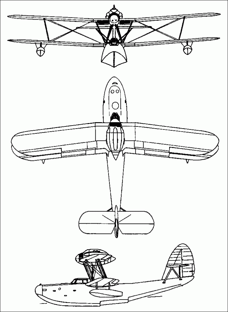
The E11A was planned to a 1936 requirement for a successor to the same company’s E10A as the noctur-nal spotter carried by Japanese battleships and cruis¬ers, and first flew in June 1937. The Aichi prototype was evaluated competitively against the Kawanishi El1K, and ordered into production during April 1938 with the full designation Navy Type 98 Night Recon¬naissance Seaplane, and the short designation E11A1 (reconnaissance seaplane, 11th in series, built by Aichi, 1st model). Including prototypes, production up to 1940 amounted to just 17 aircraft, and these saw limited operational service in the opening rounds of Japan’s Pacific campaign in the Second World War.
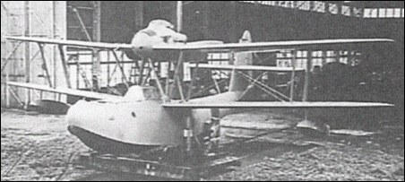
Of biplane configuration, the two-step hull carried a braced tail unit, with the tail-plane and elevator mounted almost halfway up the fin. Accommodation was provided for a crew of three, and there was an open bow position that could be used during on-water manoeuvres, or mounting a defensive machine gun. Balancer floats were mounted beneath each lower wing, close to the wingtip. The engine was a Hiro Type 91 Model 22 inline engine, mounted at the centre-section of the upper wing, and driving a pusher propeller with spinner.

E11A1
Engine: 1 x Hiro Type 91 Model 11 inline piston, 620-hp (462-kW)
Maximum speed: 135 mph (217 kph) at 7,875 ft (2,400 m)
Climb to 9,845 ft (3,000 m): 18 min 32 sec
Service ceiling: 14,520 ft (4,425 m)
Range: 1,209 miles (1,945 km)
Weight empty: 4,248 lb (1,927 kg)
Maximum take-off weight: 7,275 lb (3,300 kg)
Wing span: 47 ft 6.5 in (14.49 m)
Length: 35 ft 1.75 in (l0.7lm)
Height: 18ft 0.5 in (5.50m)
Armament: one 7.7-mm (0.303-in) machine-gun

Aichi E10A

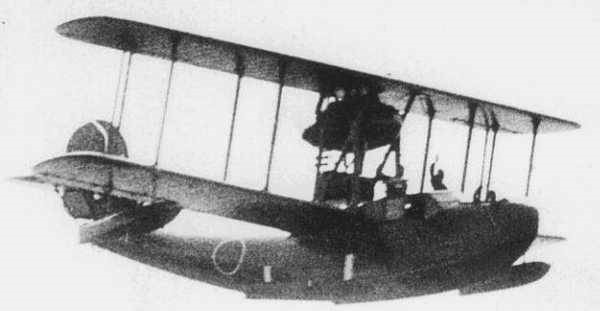
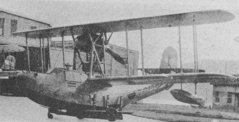
In 1934, based on experience of testing the Experimental 6-Shi Night Reconnaissance Flying boat, the Imperial Japanese Navy drew up a specification for a new night reconnaissance aircraft, intended to shadow enemy fleets during the cover of darkness, with orders being placed with Aichi and with Kawanishi.

Aichi’s design, with the company designation AB-12, was a single-engined biplane flying boat of all-metal construction. Its two-bay wings folded rearwards to save space on board ship, while its crew of three were accommodated in an enclosed cabin. It was powered by a pusher water-cooled Aichi Type 91 engine, driving a four-blade wooden propeller.

The first prototype flew in December 1934, and when tested proved to have superior stability to the competing Kawanishi E10K, and so was ordered into production.

The AB-12 entered service in August 1936 with the Japanese Navy as the Type 96 Night Reconnaissance Seaplane, with the short designation E10A. The allied code name ‘Hank’ was assigned before its appearance or manufacturer was known.

Fifteen aircraft were built for the Imperial Japanese Navy serving from 1936, remaining in service until 1941, being phased out in 1941 before the Japanese attack on Pearl Harbour.

E10A
Powerplant: × Aichi Type 91 W-12, 370 kW (500 hp) to 485 kW (650 hp)
Propeller: 4-bladed wooden fixed-pitch pusher
Wingspan: 15.5 m (50 ft 10 in)
Wing area: 52.1 m2 (561 sq ft)
Length: 11.219 m (36 ft 10 in)
Height: 4.5 m (14 ft 9 in)
Empty weight: 2,100 kg (4,630 lb)
Gross weight: 3,300 kg (7,275 lb)
Wing loading: 63.2 kg/m2 (12.9 lb/sq ft)
Power/mass: 0.113 kW/kg (0.069 hp/lb)
Maximum speed: 206 km/h (128 mph, 111 kn) at sea level
Cruise speed: 106 km/h (66 mph, 57 kn) at 1,000 m (3,281 ft)
Range: 1,852 km (1,151 mi, 1,000 nmi)
Service ceiling: 4,120 m (13,520 ft)
Time 3,000 m (9,843 ft): 17 minutes 42 seconds
Guns: 1× 7.7 mm machine gun flexibly mounted in nose
Crew: 3

Aichi AM-23 / B7A Ryusei

The Imperial Japanese navy drew up the specification for a large torpedo/ dive-bomber to replace the Nakajima B6N and Yokosuka D4Y in 1941

The experimental Nakajima Homare 11 twin-row radial powerplant developing around 1342kW was selected as the specification called for an internal bombload of up to 500kg or the carriage of an 800kg torpedo externally.
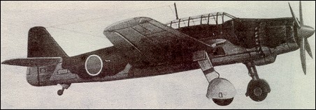
Aichi began work and its AM-23 prototype flew in mid-1942. This aircraft, then designated Navy Experimental 16-Shi Carrier Attack Bomber (Aichi B7A1), was a mid-wing monoplane of inverted gull-wing configuration, with the main units of the retractable tail-wheel landing gear, mounted at the ‘elbows’ of each wing. A section of each outer wing panel folded for carrier stowage. The fuselage and tail unit were conventional, providing enclosed accommodation for a crew of two. An underside provision was allowed for the carrying of a single 1,764lb torpedo. Additionally, two forward-firing fixed 20mm cannons were mounted in the leading wing edges. A single defensive 13mm machine gun was allotted for the rear cockpit position.

Aichi B7A Ryusei Article

It was almost two years before the type was ordered into production as the Navy Carrier Attack Bomber Ryusei (Shooting Star), or Aichi B7A2. Apart from nine prototype B7A1s, only 80 examples were completed by Aichi before its factory was destroyed in the serious earthquake of May 1945; an additional 25 were built by the Navai Air Arsenal at Omura.

By the time these aircraft entered service, when they were allocated the Allied codename ‘Grace’, the Japanese navy no longer had any carriers from which they could operate, with the result that they saw only limited use from land bases.

B7A1
Engine: Nakajima Homare 11, 1875 hp
Wingspan: 47 ft 3 in
Max speed: 337 mph at 20,345 ft

B7A2
Engine: 1 x Nakajima NK9C Homare-12, 1370kW / 2,000hp
Wingspan: 14.4 m / 47 ft 3 in
Length: 11.5 m / 37 ft 9 in
Height: 4.08 m / 13 ft 5 in
Wing area: 35.4 sq.m / 381.04 sq ft
Take-off weight: 5625-6500 kg / 12401-14330 lb
Empty weight: 3810 kg / 8400 lb
Max. speed: 565 km/h / 351 mph / 306kt
Service Ceiling: 11250 m / 36900 ft
Range w/max.fuel: 3300 km / 2051 miles
Range w/max.payload: 1800 km / 1118 miles
Crew: 2
Armament: 2 x 20mm cannons, 13mm machine-gun, 800-kg torpedo or 800kg of bombs