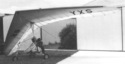
Built in 1993 with a Foil 150 wing but appeared in 2002 with a Moyes XS 155 wing
Built in 1993 with a Foil 150 wing but appeared in 2002 with a Moyes XS 155 wing

The Bolton 1-B was built after WW2.


The two-seat Bolkow Bo 209 Monsoon first flew in 1967.


Bo 209-150
Engine: Lycoming O-320, 150 hp
Prop: fixed pitch
Bo 209-150
Engine: Lycoming IO-320-D1A, 160 hp
Prop: Constant speed
Wingspan: 27 ft 6.75 in / 8.40 m
Length: 21 ft 7.75 in / 6.60 m
Empty weight: 1067 lb / 484 kg
Max payload: 504 lb / 229 kg
MTOW: 1807 lb / 820 kg
Max cruise 75% 8000ft/2440m: 148 kt / 170 mph / 274 kph
ROC SL: 1180 fpm / 360 m/min
Service ceiling: 18,100 ft / 5520 m
Max range, 65%, no res: 647 nm / 745 mi / 1200 km
Cabin length: 4 ft 7 in / 1.40 m
Cabin width: 3 ft 3.75 in / 1.01 m
Cabin height: 3 ft 6.75 in / 1.11 m
Seats: 2 side-by-side
Bo 209S
Engine: Rolls-Royce Continental O-240, 130 hp
Non-retractable nosewheel
Wing: non-folding
MBB Bolkow 209-160RV
Engine: Lycoming IO-320-D1B
prop: MT 3 blade VP
Cruise: 125 Kt
Seats: 2
Retractable Nosegear, Folding Wings


Bjorn Andreasson of Sweden, originally designed and constructed the prototype BA-7 in his garage in San Diego, while employed as an engineer at Convair. Andreasson’s BA-7 major objectives were good performance, economy, unusual visibility and maneuverability. Fifteen hundred hours of work, one thousand dollars, and a used seventy-five horsepower Continental engine was the expenditure in the project.
Andreasson first flew his 75hp Continental powered BA-7 homebuilt prototype on 10 October 1958.

The fuselage is a sheet metal box with exterior longerons and only three bulkheads. The horizontal tail is all-flying; the vertical tail has been changed to conventional fin-and-rudder combination and swept to enhance directional stability.
The wings, using an airfoll only 8.5% thick, have an extruded spar at 30 percent, and a light rear spar at 75% chord. A heavy magnesium skin adds strength, and countersunk rivetting ensures smoothness. By undoing the rear spar bolts, the wings can be folded alongside the fuselage for easy towing or storage, an attractive feature.
The visibility comes from the slight forward sweep of the wings, the occupants sitting forward of the spar. The one piece free blown canopy is hinged at the rear and held down by two latches, one of which is sufficient to hold it at maximum speeds. The main gear is built around two tapered steel rods, anchored to a box beam. The nose gear has a coil spring, is air damped, and is steared by the rudder pedals. Elevators and ailerons are actuated by a single centrally located stick; rudder pedals are dual, and a single hydraulic cylinder gives braking action to both wheels.
The flap control incorporates a nonreversing mechanism that holds the flap in any selected position. The fuel supply is positioned over the center of gravity behind the pilot, and with the 75 horsepower engine in the prototype, the twenty US gallons provides six hundred miles range. A plastic tube is used to indicate the fuel level.
Liftoff is at about sixty-five miles per hour, and an actual top speed of over 150 has been achieved. A more powerful engine is contemplated for the production version. Present approach speeds are on the order of 70-85, and touching speed approximately 55 miles per hour.

Andreasson was producing three copies of the MFI Junior, as it’s been renamed, and with Malmo Flygindustri, Mahno, Sweden, a series of ten to test its market potential.
A couple of years later Andreasson returned to Sweden where he joined up with theMakno Flygindustri company, later becoming head of the Aircraft Division of Malmo, a subsidiary of Saab Scania.
While there he put together an improved version of his BA-7, powered by a flat-four engine of 100hp. Following its test flight, the BA-7 design rights were acquired by Malmo Flygindustri and the BA-7 was renamed Malmo MFI-9 or just MFI to the team. Under the designation MFI 9 Junior, the first prototype Junior took to the air on 17 May 1961. Limited production commenced in 1962 and the first production model flew on 9 August 1962. The Junior is certificated for normal and Utility categories and for glider towing.
The basic MFI, of which 25 were produced by Malmo, had reasonably good beginnings and in 1962 Bolkow Apparatebau GmbH (Germany) became involved. Bolkow started producing the Bolkow B208 Junior as an expansion of the MFI-9 under licence to Malmo and by 1970 had produced 200 examples.

A manufacturing licence agreement was reached with the West German firm of Bölkow-Entwicklungen KG, Munich, and licensed production began in 1962 in Germany at the Bolkow factory as the Bo208 Junior.

Two years later a new model, the Bo208C, emerged with the addition of electrically operated flaps, a trailing link nosewheel suspension and a former optional longspan wing as standard. Amongst other features, the Bolkow had tubular steel main gear well before Cessna adopted the concept. The Bo208 has only required three relatively minor mandatory modifications. Its only real problem came with the nosewheel it was prone to falling off once the aircraft was airborne. The addition of the trailing link nosewheel suspension in the B model sorted that problem out. The Bolkow remained one of the fastest 100hp two seat light aircraft with a duration of four hours in the air (range 804.7km with maximum payload), cruis¬ing at 120 mph. Aerobatic. 186 built in total.
In 1964 nine examples were assembled in Burbank, California, by Pioneer Aviation, the U.S. distributor. The 1964 price was US$7800 fully equipped but minus radios, with its American type certificate A1EU.

Slab tail surfaces were featured on the prototype in original form along with a system of springs to return the elevator to neutral or trimed position. The spring tension is not affected by speed, the stick loading remains light at high speed. With an anti-servo tab the feel heavies up as the speed increases. Andreasson eventually adopted the anti-servo tab for better all-round efficiency. After some experimentation, the rectangular rudder was abandoned for the more conventional swept tail.
The large, one-piece canopy is just under 1/8in thick. It measures 38in across at the widest point and has a base length of 30in. American models have a single, centrally located canopy latch instead of the left and right side handles fitted to German aircraft. The seats are independently mounted. A luggage compartment is situated directly behind the seats and below the fuel tank. It is accessable from the cockpit only.

In order to achieve the excellent visibility from the cockpit and still keep the centre of gravity within permissable limits, Andraesson swept the wings forward three degrees. The employment of the “droop snoot” leading edge has the effect of providing a more forward centre of pressure at higher angle of attack. Structurally the fuselage has four external longerons and the skins are all flat sheets. To prevent excessive vibration, two longitudinal stiffeners are formed in each side panel. The single spar (an I-beam extrusion) wing is composed of a minimum of parts, each panel having only seven ribs. The airfoil is an NACA 23008.5 section modified at the leading edge. The main legs of the landing gear are flexible steel shafs weighing about eight pounds each.
Reinforced fibreglass mouldins are used at the wing tips and on the engine cowling. Self-aligning bolt bearings are used in such places as the top engine mount lug and fuselage wing strut fittings.
Dual throttles, located on the extreme right and left side of the instrument panel, are connected by a transverse torque tube behind the panel. Friction on the torque tube is adjusted by a small knob in the centre of the panel.
Cleveland hydraulic brakes are actuated simultaneously by a lever mounted on the left side of the central keel. A simple ratchet lock disengages easily by pulling the handle a little to one side. The anti-servo trim tab has a lever in the cockpit moving a sheathed, 1/8in steel rod connected to a 1.5in long bellcrank at the tailpost. The bellcrank, fitted with a small friction-disk brake, is linked to the tab by a short rod.
Aileron mass balance weights on the BA-7 were fully enclosed in the wing tips. They are in about the same place on the Junior, but project into the airstream with up aileron. Rudder weights are entirely external and the horizontal tail has a heavy leading edge, largely with the weight necessary for balance.
In its original form the Junior was equipped with manually-operated self-locking flaps which were quick and positive. However, the operating handle was situated above shoulder level between the occupants and on the rear cross tube. During certification tests in Germany, the inspector banged his head several times on the handle and this prompted a recommendation that the system be operated electrically. A small window actuating motor from a Mercedes 220 automobile was adapted for aircraft use.
The toggle switch controlling the flaps is located next to the throttle. A simple flap indicator is an endless sheathed cable running from the flaps to a small pointer projecting through a vertical slot on the instrument panel. The slot is marked to show any position from 0 to 35 degrees. A second, electrical fuel pump is fitted.

In the original BA-7, the elevator was not adequately powerful to keep the nose up at low speeds, which meant that the aircraft had to land faster than should have been necessary. By increasing the elevator area on the Junior and giving it an inverted camber, control was more powerful and touchdown speed was reduced. Recommended approach speed is 70 kt / 80 mph. The Junior’s ailerons are small, 32in x 10.5in, but effective and a 360 degree roll takes under 3 seconds. The landing gear is sprung, with 500 x 5 tires all round. The thrust line is offset 1.5 degrees to the right.
Empty weight has been raised from 590 lb of the BA-7 to 750 lb, due primarily to the use of aluminium instead of magnesium and the use of the 100 hp Continental with full electrical system.
Some 210 Bolkows were built in the years following 1962, ceasing in 1970.

Meanwhile, Malino had further developed the MFI-9 from which came the MFI-9B Trainer with an enlarged cabin. The 9B was purposely designed for the military as a basic trainer, although the type later became very useful in a ground attack role. Malmo, which built nearly 50 9Bs, was hoping that the Swedish Air Force would acquire its trainer, but that didn’t eventuate.

The MFI 9B was followed by a T tailed version with provision for underwing stores, evolving to the MF 15 which was used a military trainer.
About five rocketting 9Bs saw service with the Biafran Air Force during the Biafra-Nigeria Civil War in 1969, when Biafra was fighting for its independence from the much larger country. The five 9Bs actually made up the air component of the BAF, along with a few inactive Harvards. Known as “Biafran Babies”, the militarised 9Bs were flown by Swedish and BAF pilots and were up against the likes of the Nigerian Air Force’s (NAF) MiG-17 jet fighters and the much bigger Ilyushin Il-28 twin-engine jet bombers.
It is reported that the little 9Bs either severely damaged or totally wrecked numerous MiGs and three of the NAF’s six Il-28 bombers during ground attack, hit-and-run operations. Other Nigerian targets attacked by the 9Bs included key airfields, armoured vehicles, troop and transport lines and oil depots. One 9B returned to base from a low-level sortie with 12 bullet holes in it.
The 9B was also used in a ‘MiniCOIN’ role, a contraction of miniature counter-insurrection. At the end of seven months of flying combat missions, the BAF’s strike force assets numbered two. Two MFI-9Bs had been shot down with the loss of their pilots and one had been damaged beyond repair.

Bolkow Bo.208
Engine: Continental O-200-A, 100 hp
Prop: McCauley 1A 100 MCM 6758 metal fixed
Wingspan: 24 ft 4 in
Length: 19 ft
Height: 6 ft 6 in
Wingarea: 93 sq.ft
Tread: 6 ft 4 in Fuel capacity: 21.1 USG
Load factor utility: +4.40 / -1.76
Empty weight: 794 lb
MAUW utility: 1275 lb
MAUW normal: 1325 lb
Fuel capacity: 21 USG
Fuel & oil: 136 lb
Baggage: 45 lb
Vne: 153 kt / 176 mph
Max speed SL: 125 kt / 143 mph
Cruise 1500ft / 2500rpm: 106 kt / 122 mph
Cruise 9000ft / 2600 rpm: 109 kt / 126 mph
Landing speed: 51 kt / 59 mph
ROC SL 75kt: 690 fpm
Service ceiling: 13,000 ft
Cruise range 12,000ft / 2500 rpm: 480 mi
Endurance: 4 hr
TO roll: 900 ft
TO to 50 ft: 1720 ft
Landing roll: 770 ft
Landing dist from 50ft: 1480 ft
Seats: 2.
Malmo & Bolkow MFI-9HB
Engine: 100 hp.
Span: 24ft 4in.
Wing area: 93 sq.ft.
Length: 19ft 2in.
Max wt: 1268 lbs.
Empty wt: 750 lbs.
ROC: 900 fpm.
Cruise: 113 kts.
Seats: 2.
MFI-9 Junior
Number built: 25
MFI-9 Trainer
Number built: 70
Bolkow 208C Junior
Engine: Rolls Royce Continental 0-200A, 100 hp
Wingspan: 26 ft 4 in / 8.02 m
Length: 19 ft 0 in / 5.79 m
Empty Weight: 874 lb / 380 kg
Max All Up Weight normal: 1390 lb / 630 kg
Max All Up Weight utility: 1320 lb / 600 kg
Fuel Capacity: 21 Imperial Gallons (100 Litres)
Max cruise Speed: 111 kt / 127 mph / 205 kph
Max ROC SL: 785 fpm / 240 m/min
VNE: 153 kt
Service ceiling: 14,780 ft / 4500 m
Range max fuel: 538 nm / 620 mi / 1000 km
Seats: 2


First flown on 25 September 1973 (Prototype D-HDCI), the BO 106 is generally similar to the BO 105 but has the cabin widened by 50cm to seat two or three persons in front and four on the rear bench. Its uprated Allison 250-C20B engines each develop a maximum of 420shp and give 50shp more than the 250-C20 at ISA + 20°C. This gives the BO 106 a performance simflar to that of the BO 105.
An uprated transmission caters for a twin-engine power output of up to 692shp, and single-engine output of 380shp, compared with 636 and 370shp respectively for the BO 105 transmission.
The prototype was developed with government aid (60%). It is hoped to make available kits to convert existing BO 105s to BO 106 standard, as well as new production aircraft.

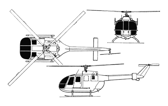
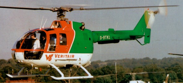
Design of the Bo.105 lightweight, general purpose helicopter was begun in July 1962 utilising basic experience gained by the company in the preceding few years in building the Bo.102 and Bo.103. The former was a non-flying, ultra-light helicopter trainer, and the Bo.103, flown for the first time on 9 September 1961, was essentially the same aircraft minus its fixed base. An enlarged version of the Bo.103 was proposed as the Bo.104, but this project was supplanted by the more promising Bo.105.
Under German government contract, ground rig testing of its radical rigid rotor and construction of the first prototypes began in 1964. The first prototype airframe (V-1) was ready for ground testing September 1969, powered by two Allison 250-C18 turboshaft engines and using the hinged-rotor from a Westland Scout, was destroyed on the ground at an early date by resonance problems. The second prototype, first flown on 16 February 1967 at Ottobrunn (Munich), was the first to take to the air with hingeless titanium rotor hub and composite rotor blades. Powered by twin Allison 250-C18 turboshaft engines, the non-articulated rotor, whose fold-able blades are reinforced with glassfibre, has been developed over several years by Bolkow in association with Sud-Aviation and has been adopted by the French company for its own SA.341 light helicopter.
Further changes and modifications led to the third prototype — the V-3 fitted with two German-built MAN-Turbo 6022 turbines (first flown on 20 December 1967), and to two pre-production models, the Bo.105 V-4 and V-5, the first of which made its maiden flight on 1 May 1969. Two Allison 250-C20 turbines were later installed on the V-4, which thus became the prototype of the definitive Bo.105C. Meanwhile, from spring 1970, new “droop snoot” design blades, which had a marked downward curvature on the leading edge, were introduced. These were made by MBB, the Messerschmitt-Bolkow-Blohm und Voss group — of which Bolkow and its affiliates had become part.
In 1972, the Bo.105 went into full-scale production at the company’s Donauwörth facility in Germany, and was offered with either Allison 250-C18 turbine engines or the more powerful C20. The helicopter was approved by the German Federal Authority LBA with the first power-plant in October 1970, after successfully completing autorotation trials in the autumn of 1969. Approval by the US Federal Aviation Administration followed in March 1971 and was extended to the C20 engines in August 1972, while the Canadian authorities certified the Bo.105 in April 1973. The German helicopter also received a British Certificate of Airworthiness in July 1973 and was recognized by the Italian Aeronautical Register in March 1974.
The German government ordered 20 for its “Katastrophenschutz” programme, to ensure rapid assistance in the event of a disaster. The military version differs little from the civil one. The antitank version can carry six HOT missiles, three on either side of the cabin, with a stabilized sight on the port side.
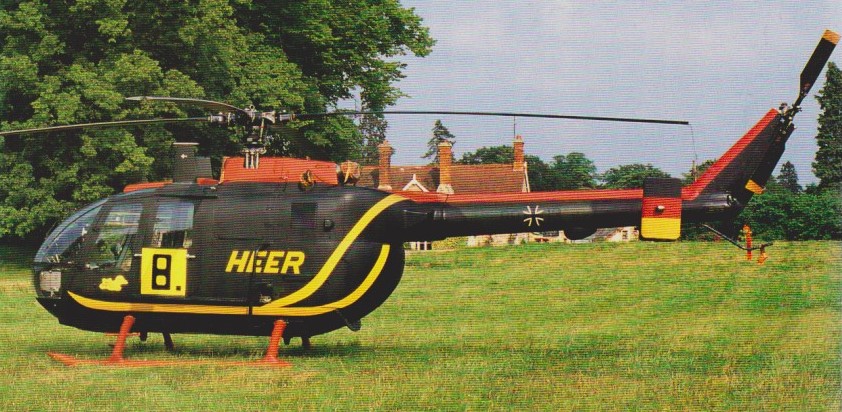
The Federal German government authorised production of a total of 439 BO 105s for service with the German army. These comprised 227 of the BO 105 M(VBH), a liaison and light observation version of which deliveries began in 1980; and 212 of the BO 105 P(PAH-1) anti-tank version, each able to carry six Euromissile HOT missiles. Initial deliveries of this latter version, to Heeresfliegerregiment 16, began in December 1980. MBB has also developed an anti-tank version able to deploy eight Hughes TOW missiles.
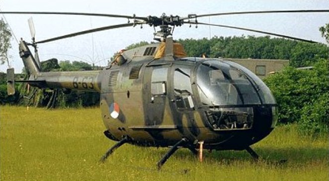
Other military operators include the Mexican navy with six radar-equipped versions used for maritime patrol, and the Spanish army with 60 BO 105Ps, 57 of them assembled by CASA. The Spanish company is also assembling 80 105s for other customers, and there are active licence-assembly programmes underway in Indonesia as the Nurtanio NBO 105, and Chile. BO 105 LS helicopters produced at Eurocopter’s Fort Erie facility in Ontario, Canada.
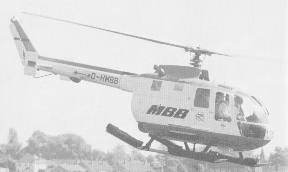
Others are in use in Brunei, Canada, Ciskei, Colombia, Holland, Iraq, Nigeria, Peru, Sierra Leone and Sweden. Sweden operates an unarmed SAR version known as the HR 9B. By 1991 more than 1,300 BO 105s had been delivered to 37 countries.
The civil version has also been a major export success and was initially marketed through Boeing in the United States before MBB set up its own US facilities. The BO 105C was superseded in 1975 by the BO 105 CB which became the standard production version.
By the end of 1981, total production of the Bo.105 exceeded 1100. More than 100 Bo.105s were in operation in the United States and these were joined in 1982 by the Bo.105CBS Twin Jet II variant, with 420shp Allison 250-C20B turbines, which, apart from having better flying capabilities, has 20 per cent more cabin room. The BO.105CB-3 variant of the standard production CB and CBS versions has a longer fuselage.
The Messerschmitt-Bolkow-Blohm GmbH Bölkow Bo.105 DBS-4 version has the 10-inch fuselage stretch at the rear of the cabin and the extra small rear side windows.
Further development of the Bo.105CBS led to the introduction in 1981 of the Bo.105LS (Lift Stretch) which combines the enlarged cabin with the uprated transmission of the military version and more powerful 550shp Allison 250-C28C engines to provide a much improved hot/high performance and external lift capability.
Bo.105 LSA3 is a stretched cabin version. Featuring two Allison C28B engines, each with a separate drive to the main transmission, separate fuel and lubrication systems and dual hydraulic boost system. Providing the lift and directional control is a hingeless four-bladed main rotor and a semi-rigid two-blade tail rotor, all of fibre reinforced composite material.
The rear-loading clamshell cargo compartment is rigged to al-low accommodation of bulky cargos or stretchers by removing the rear bulkhead behind the passenger compartment.
Sales total more than 1300 to 37 countries by 1990. Navalised BO.105s are fitted with Sperry Primus 500 search radars and other maritime equipment, and have folding main rotor blades for shipboard stowage.
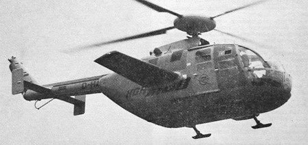
An BO 105 fitted with a rear fuselage fairing, rotor head fairing and four small individual landing gear skids, was developed under a high-speed research programme. Known as the BO 105HGH, this aircraft attained a speed of 372km/h in a shallow dive at max AUW in September 1973. Flight testing was continued in 1974 after the addition of 6.00m fixed wings with an NACA 230 section varying from 15% thickness/chord ratio at the roots to 12% at the tips. Airbrakes are mounted above and below the leading-edge of each wing, and a shorter-legged landing gear is fitted.
The HGH programme (Hochgeschwindigkeits Hubschrauber / High Speed Helicopter) ended on 4 March 1975 with a flight in which the aircraft attained a max speed of 404km/h; max blade tip speed was Mach 0.97. The BO 105HGH, which was converted from a pre-production BO 105 airframe, was to continue in use as a rotor blade testbed.
BO 105 CBS-4 description except where indicated:
DESIGN FEATURES: Four-blade main rotor, comprising rigid titanium head and GFRP blades, with titanium anti-erosion strip and pendulous vibration damper on each blade. NACA 23012 lifting aerofoil with drooped leading-edge and reflexed trailing-edge. Two-blade semi-rigid tail rotor. Tail rotor gearbox on fin. Main rotor 424 rpm. Tail rotor 2,220 rpm. Main transmission utilises two bevel gear input stages with freewheeling clutches and a spur collector gear stage. Planetary reduction gear; three auxiliary drives for accessories. Main transmission rated for twin-engine input of 257kW per engine, or a single-engine input of 283kW. Uprated transmission and Allison 250-C28 engines in BO 105 LS for exceptional hot-and-high performance. EC Super Five has new main rotor blades and performance improvements, including 150kg more rotor lift; better stability; and airframe vibration reduced to less than 0.1g.
FLYING CONTROLS: Main rotor has roller bearings for pitch change. Main rotor brake standard. Dual controls standard on EC Super Five.
STRUCTURE: Folding of two main rotor blades optional. Tail rotor blades of GFRP, with stainless steel anti-erosion strip. The fuselage is a conventional light-alloy semi-monocoque structure of pod and boom type. Glass fibre reinforced cowling over power plant. Titanium sheet engine deck. Horizontal stabiliser of conventional light-alloy construction with small endplate fins.
LANDING GEAR: Skid type, with cross-tubes designed for energy absorption by plastic deformation in the event of a heavy landing. Inflatable emergency floats can be attached to skids.
POWER PLANT: BO 105 CBS: Two 313kW Allison 250-C20B turboshafts, each with a maximum continuous rating of 298kW. Bladder fuel tanks under cabin floor, capacity 580 litres, of which 570 litres are usable. Fuelling point on port side of cabin. Auxiliary tanks in freight compartment available optionally. Oil capacity: engine 12 litres, gearbox 11.6 litres. EC Super Five additionally has scavenge oil filter and one-handed engine starting arrangement.
BO 105 LS A-3: Two Allison 250-C2BC turboshafts, each rated at 410kW for 2.5 minutes, and with 5 minute T-O and maximum continuous power ratings of 373kW and 368kW respectively. Main transmission, type ZF-FS 112, rated for independent restricted input of 310kW per engine at T-O power or 294kW per engine for maximum continuous operation; or single-engine restricted input of 368kW at maximum continuous power, or 410kW for 2.5 minutes at T-O power. Fuel capacity as for CB/CBS. Oil capacity 4.5 litres per engine.
ACCOMMODATION: Pilot and co-pilot or passenger on individual longitudinally adjustable front seats with safety belts and automatic locking shoulder harnesses. Optional dual controls. Bench seat at rear for three or four persons, removable for cargo and stretcher carrying. A full EMS version is available. Both cabin and cargo compartment have panelling, sound insulation and floor covering. Entire rear fuselage aft of seats and under power plant available as freight and baggage space, with access through two clamshell doors at rear. Two standard stretchers can be accommodated side by side in ambulance role. One forward-opening hinged and jettisonable door and one sliding door on each side of cabin. Ram air and electrical ventilation system. Heating system optional.
SYSTEMS: Tandem fully redundant hydraulic system, pressure 103.5 bars, for powered main rotor controls. System flow rate 6.2 litres/min. Bootstrap/oil reservoir, pressurised at 1.7 bars. Electrical system powered by two 150A 28V DC starter/generators and a 24V 25Ah Ni/Cd battery; external power socket; stability augmentation system standard on BO 105 LS A-3, with hoist, firefighting kit, weapons fittings, mast-mounted sight and floats optional; EC Super Five has improved hydraulic system.
Variants:
BO 105C: Initial production version offered with either 236kW Allison 250-C18 or 298kW 250-C20 turboshaft engines.
BO 105 CB: Standard production version from 1975, with two Allison 250-C20B engines, operable in air temperatures ranging from -45 to +54°C. LBA certification received in November 1976.
BO 105 CBS-5: Military army/naval version for armed and non-armed missions; can be equipped with anti-tank missiles, rocket launchers. Gun pod or turret. First 12 ordered by the Republic of Korea Army; most assembled from kits by Daewoo. Include Boeing IR/optical sights and defensive aids suite.
BO 105 CBS: version with slightly lengthened fuselage to provide increased seating or cargo capacity
BO 105 CBS-4 / Twin Jet II: Version with increased rear seat leg room in a cabin extended by a 0.25m plug. Available in five-seat executive or six-seat high-density configurations. Identified by small additional window aft of rear door on each side. Marketed in the USA by MBB Helicopter Corporation under the name Twin Jet II. First CBS version certified in early 1983 by FAA for IFR operation in accordance with SFAR Pt 29-4, requiring two pilots, radar, Loran C and a separate battery, but not a stability augmentation system, although SAS was an option.
BO 105D: UK CAA-certified offshore version with modified equipment, supplied to customers in the UK and Nigeria
BO 105 LS: Canadian-built version of BO 105 CBS with increased power for ‘hot-and-high’ operation. Combining the larger cabin of the BO 105 CBS with two Allison 250-C28C turboshafts each with a maximum take-off rating of 373kW. First flight 23 October 1981, German LBA certification July 1984, followed by FAA and Canadian DOT type approval. In Spain, CASA assembled 57 of an initial 60 for the Spanish Army.
BO 105 LSA-3: Hot-and-high version, certified 7 July 1986 and first delivered February 1987. Uprated transmission and Allison 250-C28 turboshaft engines, rated at 410kW for 30 seconds. Built solely by Eurocopter Canada at its Fort Erie, Ontario plant.
BO 105 LSA-3 Super Lifter: Optimised for external load and heavylift missions; max T-O weight 2,850kg; upgraded tail rotor derived from BK 117C-1. Type certification granted October 1995. Built solely by Eurocopter Canada.
BO 105 LS B-1: One-off testbed C-FMCL, powered by two 307kW Pratt & Whitney Canada PW 205B turboshafts, made first flight 13 October 1988.
BO 105 M (VBH): Liaison and light observation helicopter for the Federal German Army, with strengthened transmission gearing, reinforced rotor components, a tail rotor with improved thrust and performance, a rupture-proof fuel system and a landing gear able to absorb higher energy levels. Production of 100 approved by the Federal government, to replace Alouette II. Deliveries completed in 1984.
BO 105 P (PAH-1): Anti-tank version of the BO 105 M, with same airframe improvements as BO 105 M, outriggers to carry six Euromissile HOT missiles, a stabilised sight above the co-pilot and a Singer AN/ASN-128 Doppler navigation system. The Federal German government gave its approval for the procurement of 212 PAH-1s for the Federal German Army. Deliveries began on 4 December 1980 and were completed in mid-1984.
EC Super Five: High-performance version of BO 105 CBS-4, derived from German Army PAH-1 upgrade programme; certified late 1993. New main rotor blades, improved performance and reduced vibration; dual flying controls as standard.
KWS-1 upgrade programme implemented in late 1980s, including installation of a digital weapon system, reduction in launcher weight, improved cooling unit, newly developed main rotor blades, and an increase in MTOW to 2,500kg.
Specifications:
BO 105C
Engine: Allison 250 C20, 400 shp maximum, 385 shp continuous.
TBO: 1,500 hrs.
Rotor: four blade, semi rigid, glass fiber and reinforced plastic.
Length: 38 ft. 11 in.
Height: 9 ft. 7 in.
Main rotor diameter: 32 ft.
Disc loading: 6.22 lbs./sq.ft.
Seats: 5. Empty weight: 2,698 lbs.
Useful load: 2,372 lbs.
Payload with full fuel: 1,339 lbs.
Gross weight: 5,070 lbs.
Power loading: 7.9 lb/hp.
Fuel capacity (std.): 153 USG/1,033 lbs.
Fuel capacity (opt,): 258 USG/1,742 lbs.
Baggage capacity: 660 lbs.
Baggage area: 57.5 cu. ft.
Maximum sling load: 1,984 lbs.
Rate of climb: 1,250 fpm.
Service ceiling: 17,000 ft.
Single engine service ceiling: 4,200 ft.
Maximum speed: 167 mph/145 knots.
Cruise: 140 mph/122 knots.
Econ cruise: 124 mph/108 knots.
Range @ max cruise (45 min res., std. tanks): 385sm/335nm.
Range @ econ cruise (45 min res., std. tanks): 350sm/304nm.
Duration @ max cruise (no res., std. tanks): 3.5 hrs.
HIGE: 7,900 ft. HOGE: 5,850 ft. Single engine HIGE: 2,200 ft.
BO.105CB
Engine: 2 x Allison 250-C20B turboshaft, 313kW
Installed pwr: 600 kW.
Rotor dia: 9.8 m.
Fuselage length: 8.6 m.
Length rotors turning: 11.86m
No. Blades: 4.
Height: 3m
Empty wt: 1276 kg.
MTOW: 2500 kg.
Payload: 1000 kg.
Max speed: 270 kph.
Cruising speed: 270km/h
ROC: 420 m/min.
Ceiling: 5180 m.
HIGE: 2560 m.
HOGE: 1615 m.
Fuel cap (+aux): 580 lt (400 lt ).
Range with max payload: 658km
Crew: 1.
Pax: 4.
BO.105 CBS
Engine: 2 x Allison 250-C20B, 420 shp.
TBO: 3500 hrs.
Main rotor: 32.2 ft.
Seats: 5/6.
Length: 38.9 ft.
Height: 9.8 ft.
Max ramp weight: 5291 lbs.
Max takeoff weight: 5291 lbs.
Standard empty weight: 2780 lbs.
Max useful load: 2511 lbs.
Max landing weight: 5291 lbs.
Max sling load: 1984 lbs.
Disc loading: 6.5 lbs/sq.ft.
Power loading: 7.6 lbs/hp.
Max usable fuel: 1008 lbs.
Max rate of climb: 1476 fpm.
Service ceiling: 17,000 ft.
Hover in ground effect: 8,400 ft.
Hover out of ground effect: 5300 ft.
Max speed: 145 kts.
Normal cruise @ 3000 ft: 126 kts.
Fuel flow @ normal cruise: 355 pph.
Endurance @ normal cruise: 2.6 hr.
BO.105EC Super Five
Engine: 2 x Allison 250-C20.
Instant pwr: 313 kW.
Rotor dia: 9.8 m.
MTOW: 2500 kg.
Payload: 1180 kg.
Max speed: 250 kts.
Max cruise: 130 kts.
Max range: 564 km.
Crew: 1.
Pax: 4/5.
BO.105 LS
Engines: 2 x Allison 250-C28C, 500 shp.
Main rotor dia: 32.4 ft.
Height: 12.5 ft.
Skid width: 8.5 ft.
Length: 38.9 ft.
MTOW: 5732 lbs.
Std empty wt: 3153 lbs.
Max useful load: 2579 lbs.
Max ldg wt: 5732 lbs.
Disc loading: 7 lbs/sq.ft.
Pwr loading: 5.7 lbs/shp.
Std usable fuel: 150 USG/1005 lbs.
Optional usable fuel: 106 USG/706 lbs.
Max ROC: 1810 fpm.
Service ceiling: 20,000 ft.
Hover IGE: 11,500 ft.
Hover OGE: 8370 ft.
Vne: 130 kts.
Cruise: 129 kts.
Fuel flow at cruise: 335 pph.
Endurance at cruise: 3 hr.
Seats: 5/6.
BO.105P1
Engines: 2 x 420 hp / 313 kW 250-C20B
Gross weight: 5291 lb / 2400 kg
Max speed: 187 mph / 270 kph

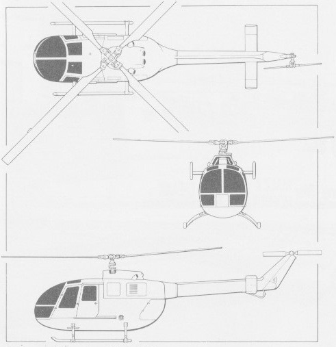
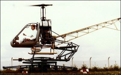
Rolled out in 1959, the Helicopter Trainer was powered by a Hirth 40hp ILO piston engine and had a twenty-one foot counterbalanced fibreglass rotor blade.
Developed in land and water based versions, both of were semi-captive. This feature allowed the helicopter to rise to a height of 0.6m, turn around a vertical axis and dip at up to 6° but prevented it from flying outside these limits.
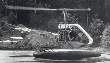
In all eighteen of these HeliTrainers were built operating throughout Europe, training military helicopter pilots. Although unable to fly, they were ideal for the teaching of hovering techniques and were replaced by dual trainer helicopters.

Bo-102
Engine: 1 x Hirth ILO, 40 hp / 30 kW
Main rotor diameter: 6.58m
Length: 5.68m
Take-off weight without a platform: 325kg
A 1960 experimental device for the development of a flying platform. Designed by Dr. Heidelberg. Lift and propulsion were supplied by several propellers. The props were driven by compressed air supplied by a compressor on the ground.
The 1911 Boland pusher biplane was designed by F.and J. Boland, and built by Boland Aeroplanes Co.
Span: 29’6″
Length: 19’6″
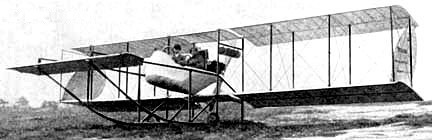
The 1912 Boland tailless pusher biplane was designed by F and J.Boland and built by the Boland Aeroplanes Co.
Span: 35’6″
Length: 21’2″

