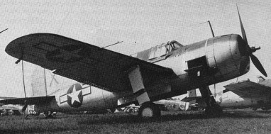
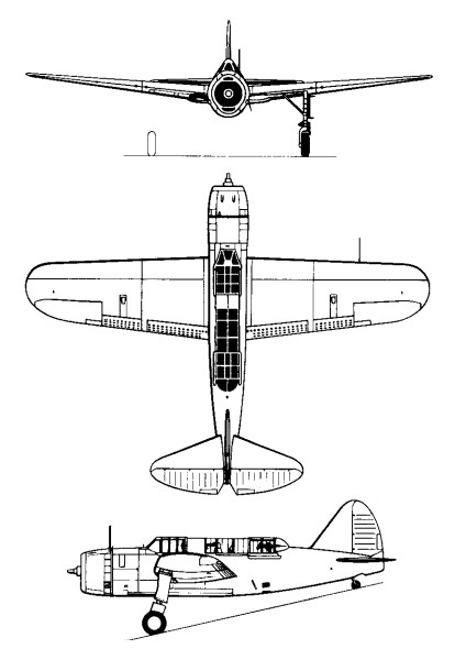
The US Navy issued a requirement for a new scout/dive bomber aircraft early in 1938. From half a dozen designs submitted, those of Brewster and Curtiss were considered most suitable, both incorporating the new 1700 hp Wright R 2600 Cyclone 14 cylinder two row radial, conforming adequately with the Navy Bureau of Aeronautics specifica¬tion. In January 1939, prototypes of the XSB2A1 (Brewster) and XSWC 1 (Curtiss) were ordered.
First flown on 17 June 1941, this was a mid-wing all-metal monoplane fitted with a 1,267kW Wright Double-Row Cyclone R-2600-8 engine. The prototype was tested with a mock-up powered dorsal turret, but this caused such buffeting that it was abandoned and traditional hand-aimed guns were used instead.
Production deliveries were made to the RAF in 1942 as SB2A-1 (known as Bermuda and quickly relegated to training and target-towing duties), and to the US Navy from 1943 as SB2A-2, -3 and -4; the latter were produced for the Netherlands East Indies but were not delivered and were used instead as trainers. The RAF’s Bermudas lacked the arrester hook and folding wings of the US Navy’s SB2As.
The Bermuda has split flaps which act as dive brakes, reducing the operational diving speed to a maximum of 240 mph.
In Great Britain, serious efforts to build a full scale rotary wing machine began in 1916, although design work on the Brennan Helicopter was initiated by Louis Brennan in 1884. At the Royal Air Establishment in Farnborough, England, Louis Brennan conducted experiments on the propeller-driven rotor concept from 1919 to 1926. The 1360kg empty weight machine used a single 18m rotor. Propellers at the rotor tips produced torqueless rotation and were powered by a 230 hp / 170kW Bentley BR-2 driving transmission shafts that ran down the length of the rotor blades. Compressed air was used to control the rotor pitch angle, through cyclic control. On 22 December 1921, indoor tethered lift tests were carried out with the assistant engineer, Robert Graham, as pilot. Outdoor tethered flights took place on 16 May 1924. A year later the Brennan Helicopter was making short flights of 18-27m at heights up to 1.5m. Power was sufficient to lift four “passengers” when tethered, but stability and control were still very poor. Over 80 take-offs were made, but the maximum altitude was only 2.4m and maximum distance only about 183m. On 2 October 1925, during the seventh small flight, the machine lurched at a height of about 1m and the rotors struck the ground, ending the tests. At this critical time in the helicopter’s development Juan de la Cierva arrived in England with his promising “autogiro” and official interest in the Brennan Helicopter rapidly faded. Finally, in March 1926 funding ceased, and Louis Brennan, at the age of 74, moved on to other inventions.
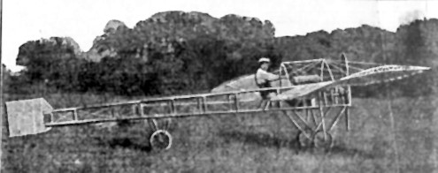
This machine was built by two brothers, Hino and Kurt Brendel, of German nationality but living in Topeka, Kansas. It made three successful, if short, flights but crashed on its fourth because of high wind. It was repaired and put on display but it’s uncertain if it flew again. In any event, the builders did not consider it very successful and built a second machine, basing it more closely on the Blériot type. One of the brothers used it in exhibition work, not only in Kansas but also in Canada.
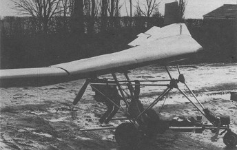
Single seat single engined high wing mono¬plane with conventional three axis control. Wing has swept back leading edge, unswept trailing edge and tapering chord; no tail. Pitch/roll control by stabilator; yaw control by tip rudders; control inputs through stick for pitch/roll and pedals for yaw. No external wing bracing; wing profile 100% double¬surface. Undercarriage has three wheels in tricycle formation; no suspension on any wheels. Flush right go right nosewheel steer¬ing connected to yaw control. No brakes. Aluminium tube framework, without pod. Engine mounted below wing driving pusher propeller. All tubing and bolts are to aircraft specification. Dave Bremner’s home¬built special uses a standard Mitchell B10 wing, the rest of the aircraft being to his own design. Certainly the most unusual aspect of the aircraft is its engine, a Suzuki twin from the GT185 motorcycle. Originally the aircraft was fitted with a 210 cc Villiers kart engine, but this suffered from two disadvantages: first it was difficult to arrange a suitable engine mounting system, and second it could only be started by swinging the prop. Dave’s search for a replacement led him to the GT185, which he chose because it has integral electric start and a horizontally split crankcase, allowing the gearbox to be re moved without expensive machining. In most respects he has built a fairly conventional machine, the cage being based on photographs and sketches of Mitchell’s own. There is no braking or suspension and the pedals are arranged so that both tip rudders can be deployed simultaneously to provide air braking. There were no plans to market the aircraft.
Engine: Suzuki GT 185, 20 hp at 6800 rpm. Propeller diameter and pitch 50 x 27 inch, 1. 28 x 0. 70 m. V belt reduction, ratio 3.0/1. Max static thrust 90 1b, 41 kg. Power per unit area 0.15 hp/sq.ft, 1.6 hp/sq.m. Fuel capacity 2.4 US gal, 2.0 Imp gal, 9.1 litre. Length overall 8.0ft, 2.44m. Height overall 4.8ft, 1.46m. Wing span 34.0ft, 10.36m. Chord at root 5.0ft, 1.52m. Chord at tip 1.3ft, 0.40m. Dihedral 6 deg. Sweepback 6 deg Rudder height 1.0 ft, 0.30 m Total wing area 136 sq.ft, 12.6 sq.m. Total stabilator area 12.0 sq.ft, 1.11 sq.m Rudder area 4.0 sq.ft, 0.37 sq.ft Wing aspect ratio 8.4/1. Wheel track 5.0 ft, 1.52 m Wheelbase 3.5 ft, 1.07 m Nosewheel diameter overall 10 inch, 254 mm Main wheels dia¬meter overall 16 inch, 406 mm Empty weight 242 lb, 110kg Max take off weight 492 lb, 223kg Payload 250 lb, 113 kg Max wing loading 3.67 lb/sq.ft, 17.9kg/sq.m Max power loading 24.61b/hp, 11.0kg/hp
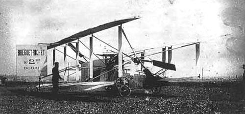
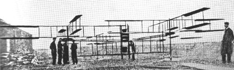
In 1908 the Breguet-Richet collaboration produced a No.2 Gyroplane, powered by a 55hp Renault engine and having two forward-tilting 2-blade rotors with a diameter of 7.85m and, in addition, fixed wings giving an extra 50sq.m of lifting surface.
On July 22, 1908, it rose vertically to the height of 4.5m and flew for a short period of time, apparently under control, but the machine was completely wrecked upon landing, but was rebuilt and flew again next spring.
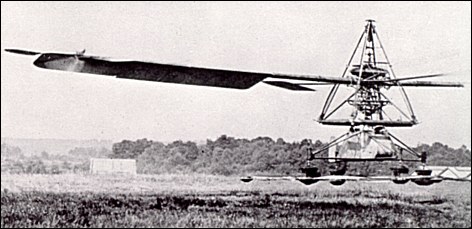
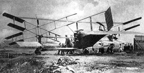
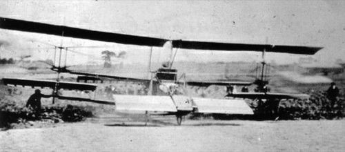
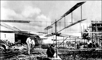
The first manned helicopter to make a successful ascent, though only with ground assistance, took to the air at Douai in France on 29 September 1907. It was built by brothers Louis and Jacques Breguet in association with Professor Charles Richet. They called it Gyroplane. Authorities differ over the date of the Breguet machine’s first flight at Douai, 24 August and 19 September 1907 being quoted with equal assurance; on this occasion the aircraft rose to about 0.60m. Take-off to some 1.50m was achieved during a test on 29 September, and similar heights were reached in several subsequent tests, but the Breguet-Richet aircraft was neither controllable nor steerable in a horizontal plane.
The machine consisted of a rectangular central chassis of steel tubing supporting the powerplant and the pilot; from each corner of this chassis there radiated an arm, also of steel tube construction, at the extremity of which was mounted a fabric-covered 4-blade biplane rotor, making a total of 32 small lifting surfaces driven by a 40 hp Antoinette engine. One pair of diagonally opposed rotors rotated in a clockwise direction, the other pair moving anti-clockwise.
Despite its weight, with pilot, of 577 kg (1273 lb), the Gyroplane rose 60 cm (2 ft) in the air, sup¬ported by four poles held by ground handlers, who dared not let go because the helicopter had no form of control save for an engine throttle. The pilot, M.Volumard, was reputedly chosen at least partly because of his small stature – he weighed only 68kg. The Gyroplane was eventually damaged after crashing into a beetroot field, and Louis Breguet turned to fixed wing craft, returning to helicopters only some 30 years later.
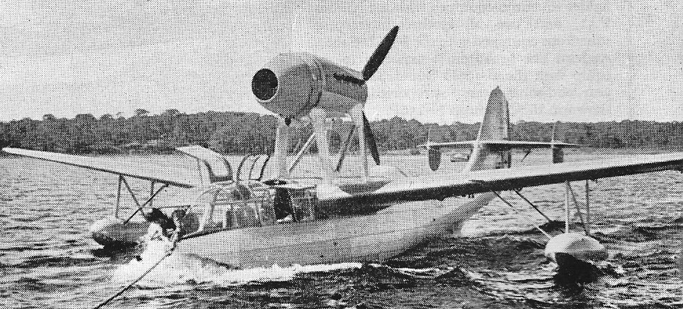
The Breguet Br.790 Nautilus light reconnaissance flying boat had completed flight tests by November 1939, and preparations were being made for the quantity manufacture of the type for the French Navy at the Toulon Arsenal at the time of the armistice.
The Bréguet Type III, which first flew in April 1910, was a development of the Type II which Bréguet had built and flown earlier that year. Eliminating the upper booms that had helped to carry the tail surfaces of the earlier aircraft, it had what is now seen as the conventional biplane configuration, with a fuselage containing a front-mounted engine driving a tractor propeller and control and stabilising surfaces mounted at the rear. At the time this was an unusual layout: the Goupy II which had first flown the previous year was the first aircraft of this configuration to be successful. Like Bréguet’s earlier aircraft, extensive use of metal was made in its construction: the structure of the rectangular-section fuselage, wing spars and interplane struts were steel, and the ribs were aluminium pressings.
The lower wings were mounted on a short spar mounted below the lower longerons and the upper wing was supported by only four struts, two inboard supporting the centre section of the wing, and one on either side connecting the mainspars of the wings near the wingtips. The mainspars of the wing panels were connected to the centre-section spar by knuckle joints, so that the wings could easily be folded back for road or rail transport.
Four small vertical stabilisers were mounted below the upper wing, and a pair of supplementary control surfaces were mounted below the fuselage. These were intended for lateral control, and were operated in conjunction with wing-warping The rear-mounted empennage initially consisted of a fixed fin and rudder and a rectangular elevator, with no fixed horizontal surface, but this was soon replaced by a cruciform assembly combining rudder and elevator, connected to the fuselage by a universal joint. This unusual arrangement became a characteristic of the aircraft manufactured by Bréguet before World War I.
The prototype was powered by a 50 hp (37 kW) Gnome Omega driving a three-bladed aluminium propeller through a 2:1 reduction gear. Later aircraft were produced with other powerplants.
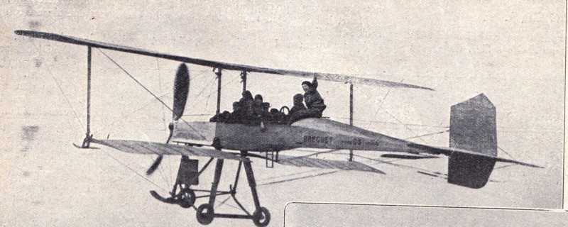
A Type III gained fame in August 1910 by being the first aircraft to lift six people.
Specifications (as shown at 1910 Paris Aero Salon) Powerplant: 1 × R.E.P. 1910 60hp 5-cyl. 2-row semi-radial, 45 kW (60 hp) Upper wingspan: 13.2 m (43 ft 4 in) Lower wingspan: 9.9 m (32 ft 6 in) Wing area: 38 m2 (410 sq ft) Length: 9.2 m (30 ft 2 in) Empty weight: 475 kg (1,047 lb)
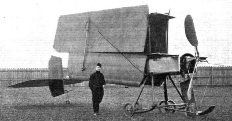
Like Bréguet’s previous design, the Bréguet Type I, the structure was principally of metal, although less highly stressed parts such as the tail surfaces used wood. It had a triangular section fuselage of wire-braced steel tube with the 41 kW (55 hp) air-cooled Renault engine at the front: this drove a three-bladed propeller which was connected to the engine’s camshaft and so revolved at half the speed of the engine. The wings had pressed aluminium ribs threaded onto a main spar of 65 mm (2.56 in) diameter steel tube. These were connected by a single interplane strut on either side. Tail surfaces consisted of a pair of horizontal surfaces, the lower carried on the rear of the fuselage and the upper by a pair of booms running back from the centre section of the upper wing. The upper surface was movable to achieve pitch control. A rectangular balanced rudder was mounted between the two horizontal surfaces. In addition, a pair of small horizontal stabilising surfaces were mounted at the front of the aircraft either side of the engine. The pilot’s seat was positioned halfway between the wings and the tail surfaces: a passenger seat was fitted behind the engine. The main undercarriage employed oleo-pneumatic suspension, and there was a single steerable tailwheel.
It was intended that lateral stability would be achieved by automatic differential movement of the two halves of the upper wing, this feature being the subject of a patent filed by Bréguet. In a turn, the greater speed of the outer wing would cause the angle of attack to be reduced, so eliminating the increase in lift that the greater speed would otherwise have produced. Lateral control was effected by a pair of mid-gap ailerons mounted on the interplane struts: these were evidently not effective and Bréguet intended to use another method for lateral control in his next design.
Its first recorded flight was made on 5 January 1910, when Louis Breguest made three circuits of the flying field at La Brayelle near Douai. and on 16 January 1910 it made a flight of 1.5 km (0.93 mi) However, by April 1910 Bréguet was flying his next design, the Type III.
Powerplant: 1 × Renault 50/60 hp V-8, 41 kW (55 hp) Propeller: 3-bladed, 2.50 m (8 ft 2 in) diameter Upper wingspan: 12.0 m (39 ft 4 in) Wing area: 40 m2 (430 sq ft) Empty weight: 580 kg (1,279 lb) Gross weight: 800 kg (1,764 lb) Maximum speed: 70 km/h (43 mph, 38 kn) Seats: 2
Bréguet and around 10 passengers above the airport of Douai in March 1911
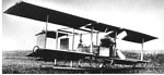
The Bréguet Type IV was developed from the Bréguet Type III which had appeared during 1910. It was a tractor biplane with a tricycle undercarriage.
The Bréguet Type IV was an aircraft built by Bréguet Aviation. It was first flown in 1911, and was the first Bréguet aircraft to be produced in quantity. It was used by the French Army and the British Royal Flying Corps. It is notable for the extensive use of metal in its construction, unusual in an aircraft of its time.
The Bréguet Type IV was produced in a number of variants, differing in their seating arrangement and in the engine fitted.
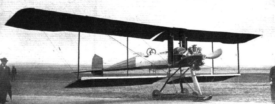
G, later G.1 powered by a 50 hp (37 kW) Gnome Omega G.2 powered by a 70 hp (52 kW) Gnome G.3 powered by a 100 hp (75 kW) Gnome Gnome Double Omega G.4 powered by a 160 hp (120 kW) Gnome Gnome Double Lambda R.1 powered by a 50 hp (37 kW) REP R.2 powered by a 70 hp (52 kW) REP L.1 powered by a 50 hp (37 kW) Renault 50/60 hp (the ‘L’ for Louis Renault) L.2 powered by a 70 hp (52 kW) Renault C.1 powered by a 40 hp (30 kW) Chenu C.2 powered by an 80 hp (60 kW) Chenu U.1 powered by an 80 hp (60 kW) Canton-Unné U.2 powered by an 80 hp (60 kW) Canton-Unné D.1 powered by a 100 hp (75 kW) Dansette O.1 powered by an 80 hp (60 kW) Le Rhône
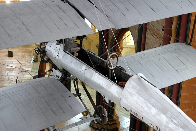
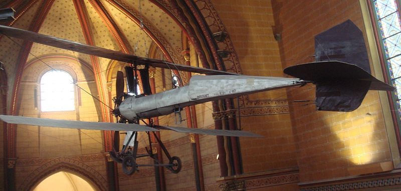
R.U.1
Although Bréguet’s earlier aircraft were referred to using a type number, the aircraft produced after the Type III were generally referred to using an airframe number and a letter/number combination denoting the type of engine fitted.
An example, an R.U.1, is on display at the Musée des Arts et Métiers in Paris.
R.U.1 at the Musée des Arts et Métiers
Breguet 1-bis of 1909 at aérodrome de la Brayelle
A large Breguet RU1 biplane.
U.I
The original 1909 Breguet U.I designed and built by Louis Breguet was later improved into the U.I-bis. Originally the Breguet biplane 1, but after a crash, it was re-designed and rebuilt. Sometimes referred to as the Breguet 2.
Number 40, of 1911 had a radial engine, two-blade wood propeller.
U.2
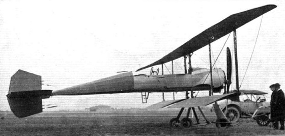
Proposed by the manufacturer to meet a military requirement, the Breguet U2 biplane was presented in various versions from 1911. The 1911 U2 version with a Salmson Canton-9 liquid cooled engine cylinder, two-bladed propeller, had the fuel tank between the two radiators placed vertically. The pilot, in back position, faced a rear-facing passenger, the other passenger, in the front, looked forward.
This machine has a steel structure fuselage, with a main landing gear with four wheels comprising two rear wheels mounted on the same axis and two front wheels detached. On early versions, lateral control was obtained by warping the wings, and later aileron control.
Initially the aircraft was equipped with a 130 hp Gnome rotary engine and was able to carry three people. Many engines were mounted on these machines, including Anzani, Renault 55 or 60 CV, and Canton-Unné of 120 hp. The propellers can be bladed or four-bladed.
U.2
Type U.2 No 45; Another military machine showing in the same Concours. A heavier aircraft than L.1 No 3, with an interwing strut between the earlier 2, retaining the original wiring. 2 tall radiators stood up under the center-section; the nosewheel was now doubled.
Type U.2 No 102: This 3-seater 2-bay single-spar biplane appeared in 1913. The 4-wheel landing gear was supported under the rear cockpit by a tall skid, keeping the cruciform tail off the ground. The fuselage was no longer a single boom aft, but consisted of 4 steel tube longerons supporting a structure faired out with stringers.
Type U.2 No 138: Similar to No 102, this new 1914 machine was a 2-bay 2-spar biplane, with 2 separate cut-out cockpits. The wing cell design was named “semi-rigide,” and the wings still warped.
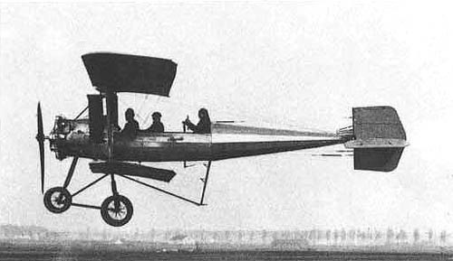
The Breguet H-U2 and U3 H seaplanes were derived from U-2 biplane. These became famous in April 1913, in Monaco, then in August of the same year in Deauville, in the hands of Henri Brégi and René sparrow.
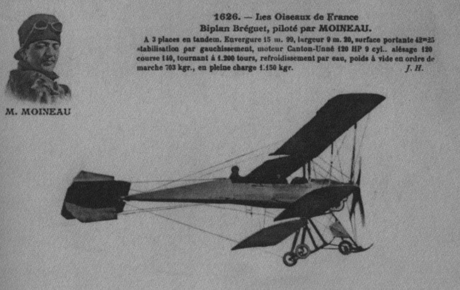
Breguet biplane U2, three-seater tandem, piloted by René Moineau
At the beginning of the First World War, the first bombing took place early in August 1914 with an attack of Frascati airship hangar near Metz by the airman Corporal Finck. Projectiles were almost exclusively former 90 or 120 caliber artillery shells. These weapons were crammed into cabins and launched by hand by the observer. Some firebombs were tried, but proved difficult to use and dangerous for the aircraft that carried them. The first months of war dart boxes (cylindrical steel rods of 12 cm long and 8 mm in diameter, tapered tip and Phillips tail to rotate to stabilize during the fall) were used. This process of low efficiency (lack of accuracy and dispersion) was abandoned in early 1915.
Used for reconnaissance missions at the beginning of the First World War these machines had rigid wings equipped with ailerons and a Salmson Canton-Unné liquid cooled 110 hp or rotary Gnome engine of 100 HP that allowed them to reach 110 km / h.
French forces employed about 30 machines.
U.2
A small batch of the popular Breguet L.2 biplane, powered by an air-cooled Renault V-8, was assembled or built by Albatroswerke, Johannisthal in Germany under license and test flown by Bréguet factory pilot Debussy in March 1912.
Breguet L.2, license-built by Albatroswerke
A myriad of versions of the Breguet biplane, were produced between 1910 and 1914. Breguet used a complex letter-number designation for the engine used in the machine. The L.2 uses a 70 hp Renault engine driving a four bladed propeller. In the Breguet system it was then coded as L (= Renault) 2 (70 hp). It might seem strange to code the Renault engine with the letter L, but the letter R was already taken by the R.E.P. engine. Code 2 stood here for 70 hp, where code 1 denoted 50 hp.
The machine had a tricycle undercarriage with a nosewheel. There were undercarriage skids to prevent the machine from nosing over. The big bulb in the front of the fuselage is the petrol tank. After the tank is a compartment holding two persons and the pilot at the back. The whole fuselage was a metal construction and in this version the big wings are two-bay.
The Breguet Biplane managed to set a world record with seven passengers.
The Royal Flying Corps (RFC) around August 1912 bought two machines of this exact type (L.2). They lasted till December 1913 but did very little flying, at most a few hours.
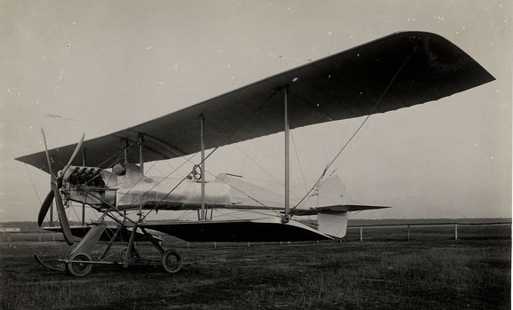
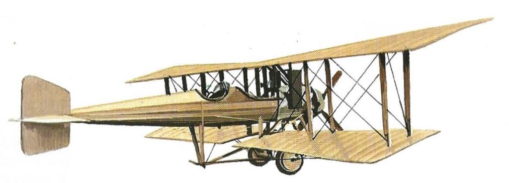
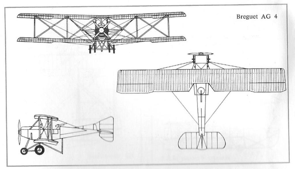
Just before the outbreak of the War, Breguet had started 2 new aircraft and projected a third. The A-G.4 was a 160 Gnome tractor; the A-U.3 was a 200 hp Canton-Unne tractor, and B-U.3 was a 200 hp Canton-Unne pusher (the A and B now used to distinguish similarly-powered machines only.)
A-G.4
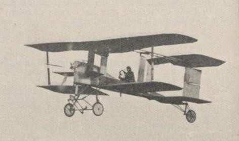
The relative success of the use of cannon in the Breguet BU.3 led the Breguet company to install it in their latest aircraft, the Breguet 5.
The French forces employed some type A-G4, the British employed some A-G4 for the Royal Flying Corps and 15 A-G4 for the Royal Royal Naval Air Service, the Italians some A-G4.
The A-G4 was the definitive 1913 military version with a rotary engine.
L-1 Cruiser Propeller: 2.4 m (8 ft) diameter Upper wingspan: 13.94 m (45 ft 9 in) Lower wingspan: 8.74 m (28 ft 8 in) Wing area: 30.43 m2 (327.5 sq ft) Length: 8.5 m (28 ft) Crew: 1 Capacity: 1
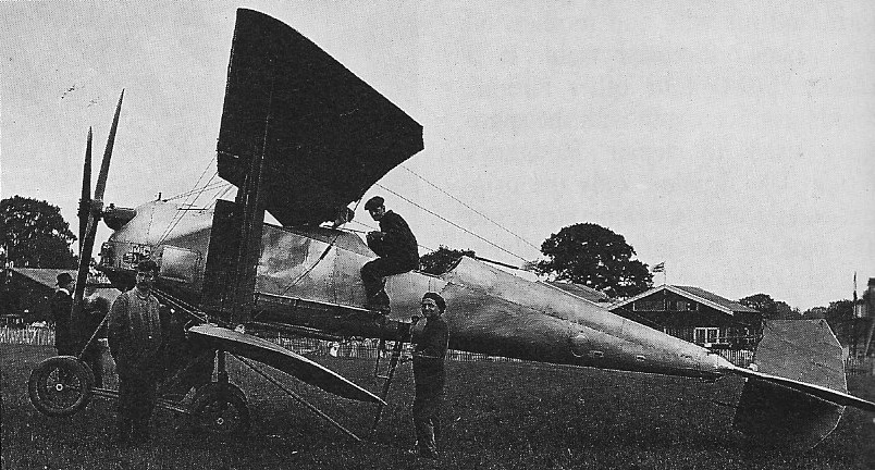
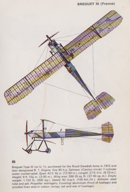
U.I Engine: Salmson Canton-Unné, 85 hp Span upper: 45′ / 13,70 m Span lower: 39’4″ Length: 30′ / 9.15m Empty weight: 1275 lb Total weight: 1150 kg Speed: 80 kph
U.I-bis Span: 41′ Length: 27’11” Weight: 1100 lb
U.2 Engine: Canton-Unné, 110 hp Wingspan: 44 ft 4 in / 13.5 m Length: 27 ft 10 in / 8.5 m Height: 8 ft 4 in / 2.5 m Empty weight: 1234 lb / 560 kg Loaded weight; 2116 lb / 960 kg Max speed: 68 mph / 110 kph Armament: none
U.2 Engine: Salmson Canton-Unné, 85 hp Wingspan: 13,70 m Length: 9.15m Total weight: 1150 kg Speed: 80 kph
A-G.4 Engine: Gnome, 160 hp Wingspan: 50 ft 4 in / 15.35 m Length: 27 ft 1 in / 8.25 m Height: 10 ft 10 in / 3.30 m Weight: 2970 lb / 1350 kg Max speed: 62 mph / 100 kph Ceiling: 42900 ft / 1500 m Armament: 1 x mg Crew: 2