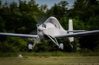
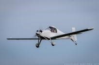
When Japan entered World War II in December 1941, the RAAF did not possess a single fighter aircraft for home defence and, consequently, a decision was hurriedly made to produce a local fighter as a stop-gap measure to meet the threatened Japanese onslaught. Fortunately, the Commonwealth Aircraft Corporation already had plans in hand for an interceptor aircraft, and this promising design was ordered into production on 2 February 1942. Thus, Australia’s first single-seat fighter came from an organisation headed by Lawrence Wackett, who was also responsible for the country’s first indigenous fighter, the two-seat Wackett Warrigal Mk II of 1930.
The Wackett was designed specifically for Australian climate conditions, and has a welded chrome-molybdenum steel-tube framework with fabric covering.
The first of two prototypes powered by the DH Gipsy Six engine was flown early in 1940. Owing to the difficulty of obtaining these engines for production aircraft, the design was modified to take the 165 hp Warner Super Scarab 165D radial engine.
The Wackett designed prototype CA-2 Wackett two-seat prototype went into production designated CA-6. Two hundred were then produced for the RAAF.
CA-6 Wackett Engine: 165 hp Warner Super Scarab 165D Wingspan: 37.01ft (11.28m) Length: 25.98ft (7.92m) Height: 9.84ft (3.00m) Empty Weight: 1,909lbs (866kg) Maximum Take-Off Weight: 2,590lbs (1,175kg) Maximum Speed: 115 mph (185kmh; 100kts) Maximum Range: 425 miles (684km) Accommodation: 2
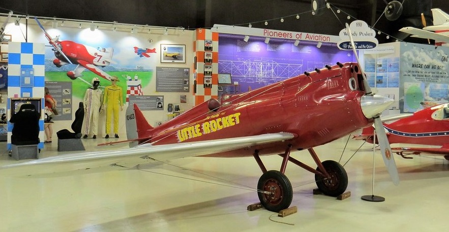
Command-Aire MR-1 Little Rocket Racer N345JA (Reproduction) on static display at the Sun’n Fun Florida Air Museum at the Lakeland Linder Regional Airport in the City of Lakeland Polk County Florida U.S.A.
Command-Aire built one little Rocket Racer. The Rocket was built to compete in the 1930 All American Derby. Equipped with a super-charged 90 hp Cirrus and Lee Gelbach at the controls, running a race course that spanned most of Mid-America, the little Rocket repeatedly recorded ground speeds of 215 mph, its average point-to-point time being in the neighbourhood of 160 mph. The aircraft won the 5,500 mile race and $15,000 prize (a fortune in the depression) with an average speed on 127mph.
The Rocket no longer exists, but Joe Armaldi in Florida built a replica of the racer.
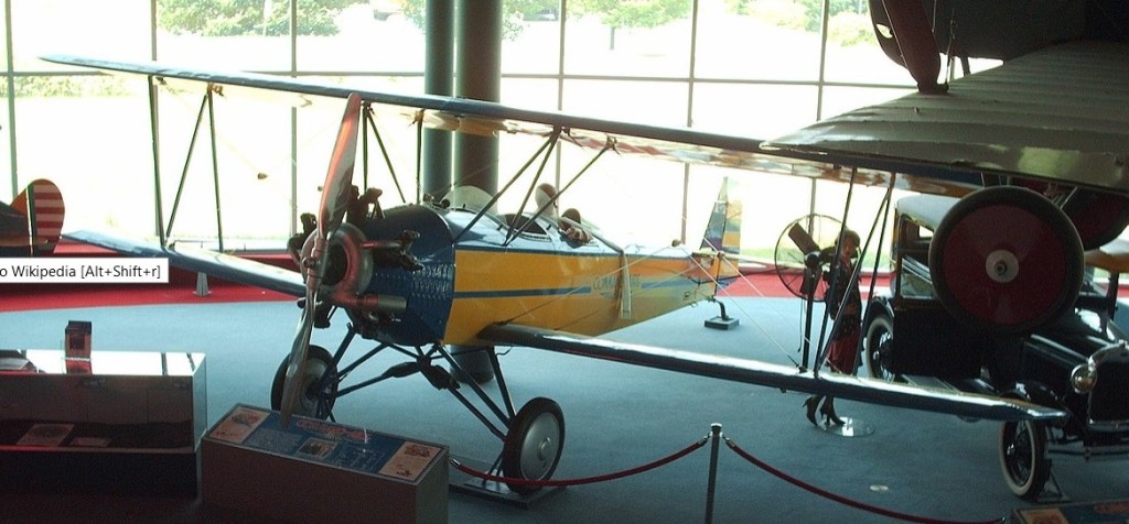
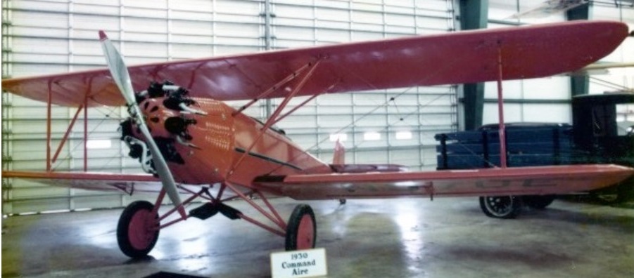
The Command-Aire did not at first appear to offer much of an advancement over the vast multitude of three seat biplanes built around the ubiquitous Curtiss OX-5 engine to similar designs, with similar dimensions and construction methods, many of which were already in production. The basic design was by Morton Cronk, and although it had excellent high altitude capabilities, it was slow. This setback nearly foundered the company before its first aircraft entered production.
Albert Vollmecke, a Heinkel engineer was in the US attempting to find a customer to build Heinkel HD 40 mailplanes under licence for the US market. Seeing that there was little prospect of any sales in the US, he decided to hire on with an American company, Command-Aire.
His first task was to rework the design to provide documentation for the new approval process. While there was only one major visible external difference, he undertook an extensive redesign based on his experience in the much more scientifically-grounded German aviation industry, and to bring the design into line with CAA (now FAA) certification requirements, which involved a lot of submissions, and alterations, and resubmissions before they signed off on it. Many parts had to be redesigned when it was easier to redo the design, than to use the existing design to calculate the necessary strength margins. The most obvious change was a switch from four small conventional ailerons at the tips to two slotted nearly full-span ailerons on the lower wing. This improved low speed control dramatically, allowing lateral control even after the aircraft had stalled – a novelty among American aircraft at the time, and a recurring advertising theme.
The second change was the incorporation of a Phylax fire suppression system capable of putting almost any fire out in flight. The third novelty was the use of a rotisserie type fuselage jig, that ensured accuracy and consistency between the airframes they built, reducing the chance of building an airplane that couldn’t be rigged to fly right. Although Command-Aire’s advertising claims that Vollmecke invented this, he claimed he merely brought the idea from Europe.
The fuselage was built from welded chromium-molybdenum alloy steel tubes, faired with wooden battens. The top of the fuselage was covered in large metal panels that could be readily opened to provide access, and a compartment for luggage was provided between the cockpits large enough for a suitcase.
The slightly staggered wings were built around solid spruce spars, with spruce and plywood warren truss type ribs. The wings were braced with cables.
The ailerons and the entire empennage were also built from chromium-molybdenum alloy steel tubing, and all controls were actuated through pushrods and bellcranks, with no cables or pulleys used. The ailerons on the prototype were conventional, however on production variants, they extended across nearly the full span on the lower wings only, and had a slot that allowed air to flow over the aileron at low airspeeds and high angles of attack, which helped ensure lateral control even after the wings had stalled. These were not Frise-type ailerons though, but conventional ailerons with a slot at the hinge line.
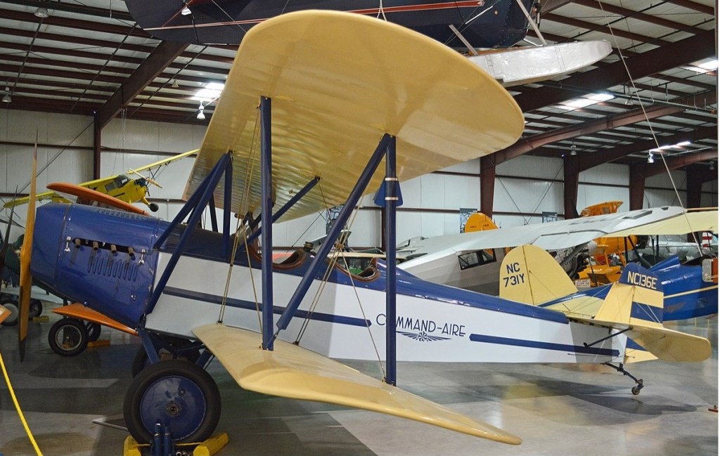
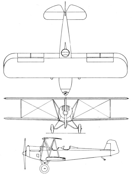
The undercarriage was a split axle type, braced to a steel tube four point pyramid that extended from the belly of the aircraft, with suspension provided with bungee cords which were protected by leather boots. Both cabane and interplane struts took the form of an N and were steel tubing as well. The 3C3 can be distinguished from later types by having an additional strut providing lateral bracing from the forward strut anchor point on the wing, to the lower longeron at the firewall, triangulating the structure. The 4C3 and later types dispensed with this extra strut, and coincided with an extensive redesign that otherwise had few external differences.
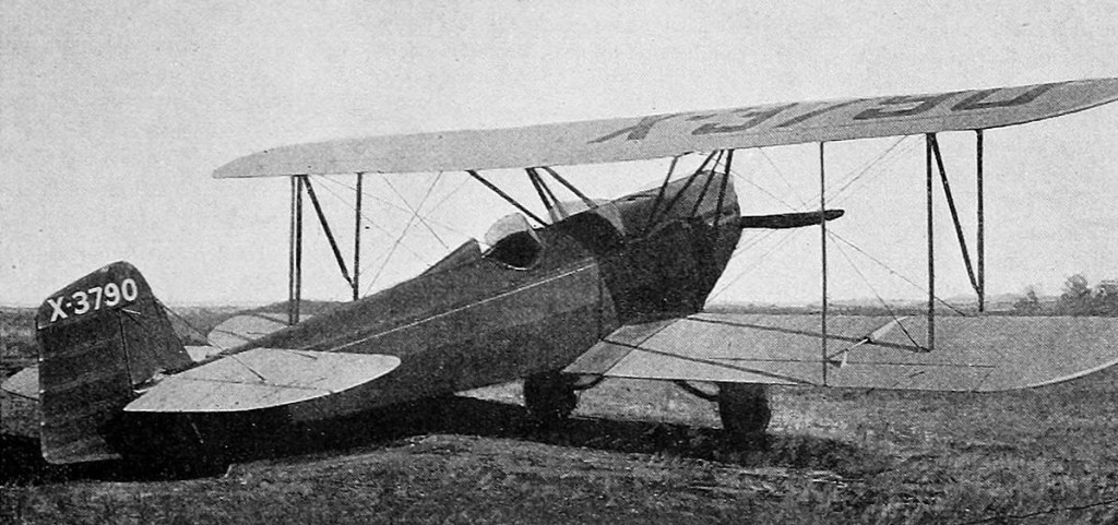
The 3C3 first flew in January 1928 and received certification in July 1928.
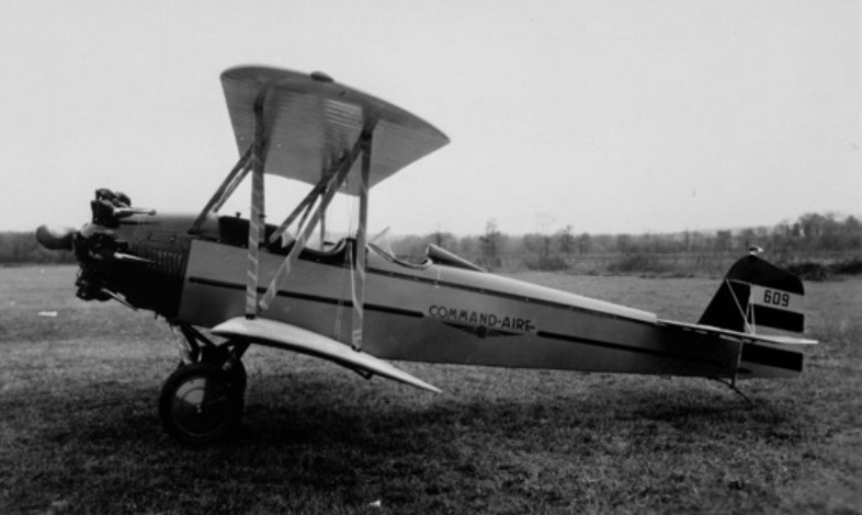
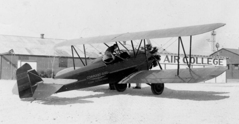
Command Aire 3C3 prototype from Aero Digest, February 1928
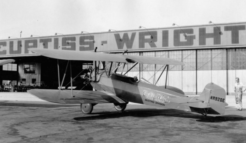
While normally a three-seat design, those aircraft with a T in the designation were built as two-seat trainers specifically for flight instruction, and a crop-dusting version was also sold, with the space in the front cockpit being filled with a large hopper, and the fuel tank relocated to the wing centre section. At least 17 of these were built, with others converted from other variants.
The 3C3 was one of the most pleasant and stable aircraft of the 1920’s. In the companies “hands off” flight demonstration, the fearless pilot would climb out of the cockpit and straddle the turtle deck like a horse while the aircraft cruised the skies, this proved a quite effective sales technique. He turned the aircraft by leaning in the desired direction.
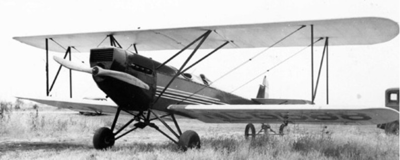
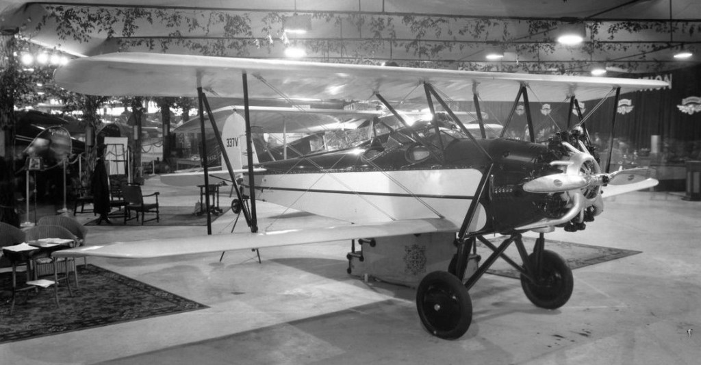
Command-Aire 3C3 NC6688 msn 513 showing salient characteristics, including triangulated cabane that was simplified on later models
The 3C3 is similar in construction to most aircraft of the period and used a war surplus OX-5 engine. One of the notable features was the metal cowls, cockpit and turtle deck which made half the aircraft metal covered–not fabric covered. The aircraft was controlled by push-pull tubes and bell cranks, there were no wires, cables or pulleys.
In another publicity stunt, a flight of over 100 mi (160 km) from San Diego to Los Angeles was made without once using the control stick as all control inputs were through the rudder pedals.
In 1929, the government decided to allow aerobatics (known as stunting at the time), during the Annual Arkansas Air Tour being held in 1929 and so a team of three Warner-powered Command-Aire 3C3-As were formed as “The Blue Devils”, but painted incongruously in black and orange stripes.
The 3C3 sold for $5500 in 1929.
The BS-14 and BS-16 (BS standing for Biplane sport) were the final developments, and again featured extensive redesign work, but once again with few visible external alterations. The rudder was redesigned, and a new and promising engine was added to the lineup – the Lycoming R-680. On the BS-16, the undercarriage was changed to the outrigger type and a tailwheel was provided in lieu of the skid used previously, while the rear seat was raised to improve visibility.
A variety of engines were installed during the life of the design, with the area ahead of the firewall being redesigned to accommodate lighter engines, with longer noses to maintain the correct balance.
The problematic engine supply situation was well understood long before the last Curtiss OX-5 was installed in an airplane, and substantial efforts for alternatives were made. Simplicity and reliability were key, and the solutions invariably involved air-cooled radial engines, however the designs were not sufficiently developed, and there were many failures, and for various reasons. As a German, it was natural for Vollmecke to look to Germany, where some of the best designs were available, however two major problems surfaced. The first was that the supply of these engines was endangered by economic instability in Germany. The second was that the Command-Aire people were never able to get their engines to run right on the fuel available. Vollmecke suspected that the octane rating was too low, which caused knocking – potentially damaging the engine. Only 7 aircraft were built with the German radials. The Czechoslovakian Walter NZ-120 was even less successful, and only one was used. The most successful of the replacement engines with Command-Aire, was the Curtiss Challenger, despite its poor reputation elsewhere. Over 50 aircraft were fitted with this engine. Had the company continued in existence, then the Wright J6 and Lycoming R-680 that were only installed in a small number of airframes, would probably have eventually outsold the OX-5 as they did with other aircraft types.
A Challenger powered-Command-Aire 5C3 was entered into the Guggenheim Safe Aircraft Competition in 1929. The 3C3 was the last aircraft not specially designed for the contest to be eliminated, and would actually enter revenue service. It later succeeded on a repeat of the test that it was eliminated on.
The Command-Aire 5C3 was featured in the Berryloid advertising series for aircraft dope, each featuring a different fabric covered aircraft, and each aircraft painted as a different bird. This advert was from the November 1929 Aerodigest
5C3 NC925E
In 1929, Command-Aire contracted the Curtiss Flying Service to handle sales, through their large number of facilities, and Curtiss purchased a large number of aircraft for flight training for their own schools. Recognizing that the excessive number of aircraft companies in the aviation industry would force consolidation into a smaller number of larger companies, it had long been the intention to merge Command-Aire into a larger company even before the onset of the Great Depression forced matters. Negotiations had been underway for just such a merger – into Curtiss, at one time the largest aircraft manufacturer in the United States, however while negotiations were still underway, Curtiss’s financial problems forced it to merge with Wright Aeronautical. Unfortunately, Wright had themselves recently absorbed Travel Air, whose offerings included the Travel Air 2000 which was similar to the Command-Aire biplanes. Negotiations collapsed, and along with them, went the contracts for supplying the flying schools – and access to the sales network.
Command-Aire landed a by now much needed contract from the Chilean government to produce 36 3C3-BTs to be built at a specially-built facility in Chile, however no Command-Aires seem to have been either used in that country, either civil or military.
Only one example appears to have been exported, a 3C3 that went to Canada in 1931, where it went through a succession of private owners as CF-APQ, having previously been NC5590 in the US.
Produced 1928-1931a total of 184-254 (total for 3C3, 4C3, 5C3, BS-14 and BS-16) were built/
1928 ATC 53, 2-201 Engine: 90 hp (67 kW) Curtiss OX-5 Propeller: 2-bladed Wooden fixed pitch Upper wingspan: 31 ft 6 in (9.60 m) Upper chord: 60 in (1.5 m) Wing sweep: 0° Lower wingspan: 31 ft 6 in (9.60 m) Lower chord: 60 in (1.5 m) Wing area: 303 sq ft (28.1 m2) Airfoil: Aeromarine 2A Length: 24 ft 6 in (7.47 m) Height: 8 ft 4 in (2.54 m) Empty weight: 1,410 lb (640 kg) Gross weight: 2,200 lb (998 kg) Useful load: 790 lb (360 kg) Fuel capacity: 40 US gal (150 l; 33 imp gal) Oil capacity: 4 US gal (15 l; 3.3 imp gal) Maximum speed: 100 mph (160 km/h, 87 kn) Cruise speed: 85 mph (137 km/h, 74 kn) Minimum control speed: 36 mph (58 km/h, 31 kn) Range: 440 mi (710 km, 380 nmi) 116 built. Crew: One Capacity: Two Undercarriage track: 87 in (2.2 m)
3C3-A 1929 ATC 118 Engine: 110 hp (82 kW) Warner Scarab 20 built. 1 fitted with Edo floats.
3C3-AT
3C3-AT N970E W-108
1929 ATC 151 2 seat trainer developed from 3C3-A about 6 built.
3C3-B 1929 ATC 120, 2-440 Engine: 105 hp (78 kW) Siemens-Halske Sh 12 5 built 1st possibly modified from 3C3 with a new c/n.
3C3-BT 1929 ATC 209 Engine: 113 hp (84 kW) Siemens-Halske Sh 14 2 seat trainer developed from 3C3-B. 2 built plus 1 converted from 3C3-B.
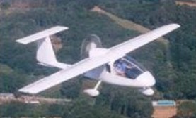
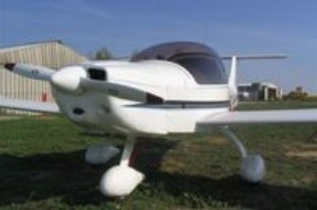
Eyeing entry into the U.S. market in 2012 was the Colyaer Freedom S100, a long-wing, composite Spanish entry that was ASTM-certified (#44) but lost its distributor. In 2012 a Lakeland, Fla., dealer was working on reintroducing it to America.
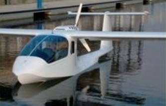
The Colyaer Gannet S100 is a seaplane that shares the wing, tail and upper fuselage of the Colyaer Martin 3. It has a water rudder and an optional reversible prop. On both airplanes, the engine is in the rear, which means less noise and greater visibility. Both the Colyaer Martin 3 and the Colyaer Gannet S-100 are made of Kevlar, which has a better strength-to-weight ratio than fiberglass, making the airplane both strong and light.
Stall: 35 kt / 40 mph / 65 kmh Cruise: 97 kt / 112 mph / 180 kmh VNE: 140 kt / 162 mph / 260 kmh Empty Weight: 270 kg / 595 lbs MTOW Weight: 450 kg / 992 lbs Climb Ratio: 1000 ft/min / 5 m/s Glide Ratio: 20 Take-off distance (50ft obstacle): 140 ft / 43 m Landing distance (50ft obstacle): 140 ft / 43 m
Ultralight Motorglider also with shorter wingspan model 110 with better cruise; 200km/h. The Colyaer Gannet S100 is a seaplane that shares the wing, tail and upper fuselage of the Colyaer Martin 3. On both airplanes, the engine is in the rear, which means less noise and greater visibility. Both the Colyaer Martin 3 and the Colyaer Gannet S-100 are made of Kevlar, which has a better strength-to-weight ratio than fiberglass, making the airplane both strong and light.
Stall: 35 kt / 40 mph / 65 kmh Cruise: 97 kt / 112 mph / 180 kmh VNE: 140 kt / 162 mph / 260 kmh Empty Weight: 270 kg / 595 lbs MTOW Weight: 450 kg / 992 lbs Climb Ratio: 1000 ft/min / 5 m/s Glide Ratio: 23 Take-off distance (50ft obstacle): 390 ft / 120 m Landing distance (50ft obstacle): 390 ft / 120 m
Grumman began designing the G-42 in mid-1939 as a successor to the J2F Duck but as a consequence of wartime priorities this was transferred to Columbia as the Columbia JL.
A total of three were produced.
XJL-1 Type: 6 place military utility amphibian Engine: 1 x Wright R-1820-56 Cyclone, 1200 hp Prop: 3 blade CS metal Max speed: 174 mph Cruise speed: 119 mph Range: 2070 miles MTOW; 13,000 lb Wing span: 50 ft 0 in Length: 45 ft 11 in
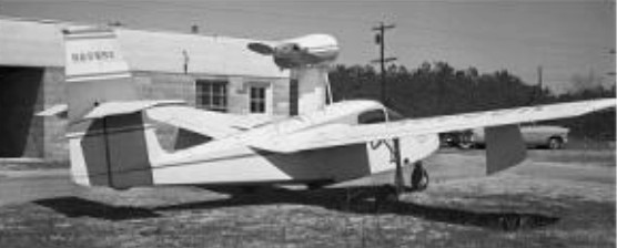
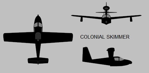
Following World War II, aircraft designer David Thurston, then of Grumman, formed the Colonial Aircraft Corporation as a side job, beginning work on a two/three-seat amphibian, the “Skimmer”. Using some ideas from his previous association with the Gooyear GA-1 Duck and Grumman G-65 Tadpole, Thurston built an all-new amphibian design with a shallower hull and raised turtledeck. Construction on the prototype, called the C-1 Skimmer, began during 1957, powered by a 115 hp Lycoming O-235-C1 with an Aeromatic propeller.
The all metal hull was semi-monocoque and the fully cantilevered wings joined the fuselage in the high mid-position.
Directly from the G-65 was a tricycle undercarriage retracting system in which the main wheels folded into the wings and one-piece, streamlined stabilising floats. The nose wheel, when retracted, left half of the tire exposed to act as a bumper. Flight control configuration was conventional, with flight surfaces manually actuated, except it appears for hydraulically-actuated flaps; there was a fold-down sea rudder at the base of the air rudder. Access was through a hinge-up front windscreen panel on each side, with side-by-side seating up front and a baggage area behind, which could alternatively handle a second passenger sitting sideways.
C-1 Skimmer
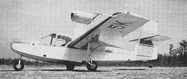
The Skimmer C-1 was a small flying boat of all-metal construction, with mid-mounted wings featuring a noticeable dihedral and fixed fin-style floats. It had a tail with a mid-mounted tailplane, and tricycle landing gear – all gear assemblies with single wheels, the main gear pivoting from the wings in towards the fuselage the nose gear semi-retracting upward into the nose. Ground steering was by differential braking, the nosewheel being free-castoring.
The C-1 prototype, registered N6595K, made its first flight on 17 July 1948 and was further developed over the next six years. The Type Certificate was achieved in September 1955. By that time Thurston had quit Grumman and was working at Colonial full-time. Changes included the installation of a 95 kW / 125 hp Lycoming O-295-D engine.
Production totals of the C-1 Skimmer are given as 22 up to late 1957. It led to the improved “C-2 Skimmer IV” during 1957, which was externally all but identical to the C-1 Skimmer, the primary change being an uprated O-320-A1A engine providing 135 kW (180 HP), permitting a higher maximum takeoff weight, enlarged horizontal tail surfaces, modified wing floats, plus structural strengthening of the wings and pylon for the increased gross weight. It was said to have seats for four, with a cabin redesign. The Type Certificate came in December 1957 and twenty C-2s had been completed at the time Colonial sold its assets, after a series of difficulties and shufflings, to Lake Aircraft Corp in late 1959.
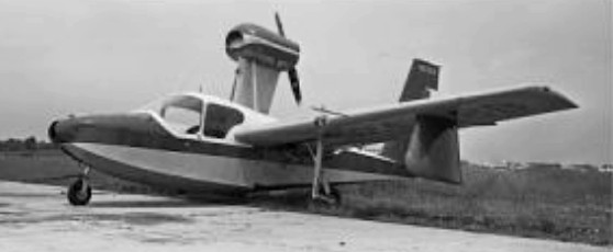
Lake Aircraft Corp marketed the aircraft initially as the Lake Skimmer, and developed the aircraft into the LA4. The initial Lake prototype, the “LA-4P”, very similar to the C-2 Skimmer, performed its initial flight in November 1959; it was followed by two “LA-4A” prototypes in 1960, which featured a 1.22 meter (4 foot) wingspan stretch and structural reinforcement.
A total of 43 (all versions) were built.
C-1 Skimmer Engine: 125 hp Lycoming O-290-D Seats: 2-3 Max speed: 125 mph Cruise: 155 mph ROC: 700 fpm Range: 700 mi Empty weight: 1300 lb Loaded weight: 1950 lb Wingspan: 34 ft Length: 23 ft 6 in Height: 8 ft 10 in Wing area: 150.6 sq.ft
Type: 2 place civil amphibian Engine: 1 x 180 hp Lycoming O-360-A5A Prop: 2 blade Constant speed, metal Max speed: 135 mph Cruise speed: 130 mph Range: 625 miles Empty weight: 1525 lb MTOW: 2350 lb Wingspan: 34 ft 0 in Length: 23 ft 6 in Wing area: 170 sq.ft