The 1909 Cuthbertson I and II pusher biplane were designed by Cuthbertson and built by the Michigan Steel Boat Co. in the USA.
Span: 30′
The 1909 Cuthbertson I and II pusher biplane were designed by Cuthbertson and built by the Michigan Steel Boat Co. in the USA.
Span: 30′
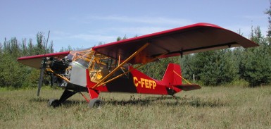
The LSA LITE STAR is the essentials and returns to the simplicity of stick and rudder. Low & slow in a gentle, agile airplane, makes flying fun again. This engine burns 5 USGPH and maintenance can be a DIY bonus. Parts & service on the engine & propeller are reasonable and inspections are minimal. A professionally welded, 4130 fuselage, and wings built with proven, extruded aluminum “I beam” spars, from a shop with 27 years experience building high performance aircraft. Gas tanks are in the wings, not the fuselage, for added safety. A high wing, tail dragger, side by side seating, fabric covered 4130 welded tube fuselage, fabric covered aluminum structure wings. Wheels, skis, or floats.
Gross weight: 1235-1350 Lbs.
Empty weight: 650 Lbs. With Corvair or Continental O-200
HP rating: 80-100 HP (can also use Rotax, or Continental O200)
Propeller: ground adjustable fixed pitch
Gear: Tail wheel configuration / shock cord suspension
Cruise Speed: 100 MPH
Stall speed: 35 MPH
Rate of Climb: 600-700 Ft/min.
Fuel capacity: up to 2×10 US gal.
Endurance: 4 hrs
2009 PRICE LIST;
1) $22,000 US for Airframe kit, all structural components welded and painted. Includes, fuselage, tail, landing gear legs, control sticks, rudder pedals, engine mount, fire wall, doors, windshield & windows, wing kit with gas tanks.
2) $60,000 US for complete LITE STAR aircraft ready to fly. Basic instrument package includes air speed, altimeter, compass and slip ball , 12-volt system with master solenoid & battery. Basic engine instruments include RPM, CHT, oil temperature, oil pressure light. Any additional instruments or radio equipment is at extra charge.
Cruise: 100 mph
Stall: 45 mph
Range: 400 sm
Rate of climb: 1000 fpm
Takeoff dist: 200 ft
Landing dist: 200 ft
Engine: Corvair , 110 hp
HP range: 65-110 hp
Fuel capacity: 20 USG
Empty weight: 650 lb
Gross weight: 1320 lb
Length: 21 ft
Wing span: 30.5 ft
Wing area: 160 sq.ft
Seats: 2
Cockpit width: 39.75 in
Landing gear: tailwheel
Designed by Morgan Williams Jr.
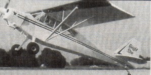
Custom Flight Ltd., of Midland Ontario, has introduced a new kit aircraft called the Bright Star. In response to requests for a lower priced version of the North Star, the Bright Star was developed. It retains the high quality standards and size of the North Star, but with some of the “extras” left off. The Bright Star has a single, larger door, no flaps, spring steel gear, a square tail, and smaller gas tanks. The gross weight is 1800 pounds and it can use aircraft or auto engines from 100 to 180 hp. It will be licensed in the experimental/amateur built category.
As of June, 2000, the prototype Bright Star has not flown yet.
The North Star fuselage strength was retained in the Bright Star to allow use of a great range of engines, from 100 hp to 180 hp. Many of the wing reinforcements in the North Star were to accommodate the very powerful flaps. By eliminating the flaps from the Bright Star we were able to lighten the wing structure, lower the price, and produce a wing with the same strength as the Super Cub wing and the improved lift of the North Star. The North Star wing can be put on the Bright Star Fuselage for a little more money, this however defeats the concept of keeping the cost as low as possible. The larger North Star gas tanks can be used in the Bright Star wings. The Bright Star has a squared off tail, and a trim tab instead of the jack screw, the same as Champs and Citabrias. This tail works fine and is more economical to produce.
There is only one door on the Bright Star and it is not split like the Cub door. It is one piece and similar in size to the Champ door making cockpit access easier. The door is hinged on the top so that it opens up against the wing and provides unobstructed access from in front of or aft of the wing struts.
A leaf spring landing gear similar to that used on the Citabrias and Cessnas is substituted for the more complicated Cub style gear.
Another way we reduced the purchase price was by eliminating the “bird cage” framework on top of the fuselage, and the belly framework under the fuselage. Instead tabs were welded on to allow the attachment of simple wood or aluminum framework made by the builder. Inexpensive wood stringers can also be supplied by the builder to keep the cost down or aluminum stringers can be purchased from CF Ltd.
Construction details
WINGS:
-Compression struts in line with aileron hinges, forces travel in a straight line instead of zig-zaging through the spars.
-raked wing tip gives long trailing edge, maximizing aspect ratio and increasing effective wing span, does not block visibility.
FUSELAGE:
-2 1/2″ wider in cockpit area.
-one larger door, 35″ tall x 46″ wide hinges up to bottom of wing.
-door handles on outside and inside of door.
-baggage floor lowered to bottom longerons.
-high ceiling in baggage area.
-90 lb. baggage capacity.
-deep “V” belly provides good drainage away from longerons and room to route cables under floor.
-belly opening at tail end, can put a garden hose in the front and flush dust and dirt out of the aft end, tail post left exposed so will not trap corrosion causing dirt and moisture.
-flat back on fuselage follows wing contour, creating lift.
-toe brakes, with parking brakes.
-instrument panel easily hinges down for access to instrument backs, is shock mounted, top edge is padded and dash edge fits under top panel flange so it cannot cut pilot in a crash.
-boot cowl (around pilot’s feet) easily removable for access by removing 2 piano hinge pins.
-dynafocal or straight engine mount.
-no sheet metal screws – nut plates welded and riveted in mean no screws to come loose or holes in tubing to introduce moisture.
-fuselage sandblasted with extremely fine sand, epoxy primed.
-tail wheel spring front bolt in a welded bushing to keep water out.
-all control stops adjustable, tail stops mate with discs not bellhorn edges to reduce wear.
-fin offset for trim.
-stainless steel tail brace wires.
-extra cable fairleads so cables cannot chip paint on tubes.
-one large handle on the right side of rear of fuselage.
-strength increased in high load areas, closer trusswork in aft fuselage.
-leaf spring landing gear is taller for long prop clearance, also gives increased angle of attack, producing lower takeoff and landing speeds, has wider wheel base, so greater stability.
-steps on landing gear give access to top of wing and easier entry to cockpit.
-front and rear seats fixed in place.
-dual controls.
Bright Star
Engine: Lycoming O-360, 180 hp
Hp range: 100 to 180 hp.
Fuel capacity: 23 U.S. gal./ 20 Imp. gal.
Wing span: 36 ft 4 in
Wing area: 190 sq. ft.
Length: 23.5 ft
Height: 7.5 ft
Gross weight; 1800 lb
Empty weight/: 1000 lb
ROC: 1000 fpm
Top speed; 140 mph
Cruise; 100 mph
Stall; 35 mph
Take off distance; 225 ft
Landing distance: 275 ft
Seats: 2
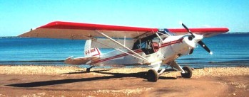
Designer Morgan Williams Jr. started with a Super Cub design to build a better aircraft. The design of the North Star had four parameters. It had to be stronger, more durable, fly better, and be easier to work on.
There were weak spots in the Cub that were known but really show up when raising the gross weight. The SC is a J3 with a higher gross and a bigger engine. With an added extra set of diagonals to the fuselage, shortening the spans in a structurally sound way. The wings are similarly strengthened with the spar reinforcements copied and improved from the Pawnee crop duster. Many more durability and other enhancements are listed in the construction specs.
The landing gear legs are 3″ taller to give higher angle of attack for better takeoff.
The sheet metal on the top of the leading edge is extended to about 4″ aft of the front spar. This gives a truer airfoil shape without the concave fabric between ribs in this critical section of the wing. The back of the fuselage is not the typical “peaked roof” as seen on most Cubs. Piper flattened the back on the agricultural models to facilitate a hopper door. By chance, since the back more closely followed the wing shape, they found the “A” models had a slightly lower stall speed.
The trailing edge of the wing is extended. This wing has 3 feet more effective span on each side. The longer trailing edge also puts the aileron outboard 2 feet. The aileron, like the flaps, also has greater cord and better airflow through the slot. All the North Stars are rigged flat, no washout.
The flaps are larger, 2′ longer and 4″ wider cord than cub flaps. The superior hinge geometry, and the redesigned radiuses on the aft bottom portion of the wing ribs of the North Star, produce the improved, energised, air flow through the large slot that adheres to the top surface of the flap, making the slow speed performance exceptional. With no flaps the North Star lifts off at 35 mph. With 20 degrees of flap it jumps into the air on takeoff at 25 mph, and climbs! This low speed means less ground wasted accelerating. Full flaps, no power on approach gives 800 FPM descent. Just touch the throttle to 1200 RPM and the path flattens out giving excellent descent control. Sideslips also work and when performed with full flaps can give 1,000-1,500 FPM rate of descent. After you become familiar with the airplane a normal approach will be full flap, 40mph, no power, over the trees, sideslip, straighten, flair, flaps off, brakes on.
The shocks are a hydraulic shock/coil spring combination. The long stroke and hydraulic shock damping give much superior protection from those extra rough landings.
Along with the kit, supplied is instructions on videotape, and a dozen 24″ x 36″ blue prints with full size details of the wing are included. For the fuselage: full size patterns for the floor boards and interior panels are supplied with a video to show how to make and install the interior. A binder is provided with 2 separate parts lists: hardware order lists with recommended suppliers and hardware location lists that tell where each bolt, pulley, etc. goes in the airplane. The binder also contains CAD detail drawings, indexed for the various areas and systems of the plane. It is set up so that new drawings can be added as they are created.
Fuel tanks in wings are welded .040-5052 aluminum and hold a total of 52 U.S. gal/44 Imp. gal./197 L.
-2 doors.
-baggage door.
-baggage floor lowered to bottom longerons.
-baggage floor extends 52″ aft.
-90 lb. baggage capacity.
-stainless steel belly framework, corrosion proof even if moisture does collect in belly.
-6″ travel in adjustable front seat with tilting back.
-rear seat tilts and lifts out for more cargo.
-fish pole/ski tube behind baggage (option).
North Star
Engine: Lycoming 0320 (150 hp).
HP range: 150-180.
Wing span: 36 ft 4 in
Height: 6.8 ft.
Length: 22.5 ft.
Wing area: 190.7 sq.ft.
Empty weight: 1170-1250 lbs.
Gross weight: 2000-2200 lbs. (2300 on floats)
Fuel capacity: 52 U.S. gal./44 Imp. gal./197 L.
Speed max: 140 mph.
Stall speeds at 2200 lb:
40 mph, No Power, No Flaps.
35 mph, No Power, or Full Flaps.
35 mph, Full Power, No Flaps.
30 mph, Full Power, Flaps.
25 mph, Full Power, Full Flaps.
Cruise 82-41 prop and 600-6 wheels: 98 mph.
Cruise on 2000 floats: 85 mph.
Lifts off: 45 mph in 500 ft
Climb: 600 fpm through 4,000 ft.
Baggage: 90 lbs.
Take off roll 180 ft
Lift off and land-on floats: 35-40 mph, 9 seconds
Range: 600 sm.
Service ceiling: 16,000 ft.
Seats: 2.
Landing gear: tail wheel.
Cockpit width: 29 in
A side by side, two seat, single engined, high-wing monoplane with conventional three axis control. Wing shape; tapering chord; yaw control by fully flying tail, circa 1982.
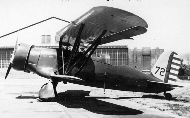
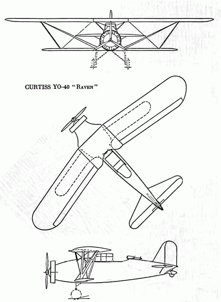
In 1931, in response to a United States Army Air Corps requirement for a new observation aircraft, Curtiss designed the Model 62, a single-engined biplane with the lower wing much smaller than the upper, known as a sesquiplane (i.e. “one-and-a-half wings”), while the outer panels of the upper wings were swept back to avoid centre-of-gravity problems. The lower wing was connected to the upper wing by one set of struts. It was of all-metal construction, with a monocoque fuselage and had a retractable tailwheel undercarriage with inwards retracting mainwheels, and was powered by a Wright Cyclone radial engine. The crew of two sat in tandem in open cockpits. It was armed with one fixed forward firing .30in machine gun in the right upper wing and one flexibly mounted .30in gun in the rear cockpit.
A prototype (sn 32-343), designated YO-40, flew in February 1932. It crashed on 20 May that year, and had to be returned to Curtiss where it was rebuilt with stronger wings and an enclosed cockpit as the YO-40A. The YO-40A was scrapped in 1938.
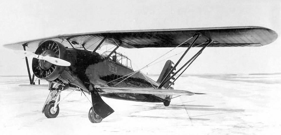
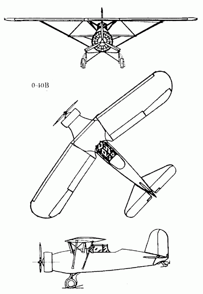
A further four YO-40As were ordered, but they were redesigned as monoplanes by removing the lower wing, the resultant aircraft being designated Y1O-40B. A stub of the lower wing had to be retained as it contained the retractable landing gear. The engine was upgraded to a more powerful R-1820-27 and the wingspan reduced by 2ft 4in. The new aircraft were heavier than the original prototype, and their performance was generally worse.
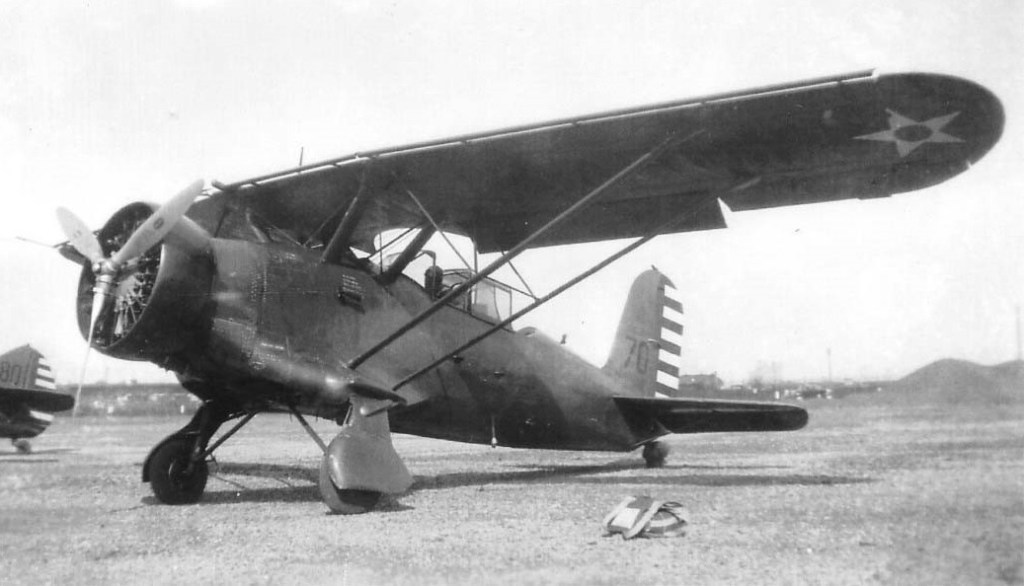
The four Y1O-40Bs (sn from 32-415 to 32-418) were delivered in June 1933, and after service tests, were re-designated O-40B Raven, being operated by the 1st Observation Squadron of the USAAC. While the aircraft’s performance and manoeuvrability were good, the Air Corps was disappointed with the cockpit arrangements and the low fuel capacity, and no more orders followed. The last O-40B was withdrawn from use in 1939.
YO-40
Engine: Wright R-1820E Cyclone, 653 hp / 487 kW
YO-40A
Y1O-40B / O-40B
Engine: Wright R-1820-27 Cyclone, 670 hp / 500 kW
Wingspan: 41 ft 8 in (12.70 m)
Wing area: 266 sq.ft (24.7 sq.m)
Length: 28 ft 10 in (8.79 m)
Height: 10 ft 8 in (3.25 m)
Empty weight: 3,754 lb (1,703 kg)
Gross weight: 5,180 lb (2,350 kg)
Maximum speed: 187.7 mph (302 km/h; 163 kn)
Cruise speed: 160.5 mph (258 km/h; 139 kn)
Stall speed: 62 mph (100 km/h; 54 kn)
Range: 324 mi (282 nmi; 521 km)
Service ceiling: 23,100 ft (7,000 m)
Rate of climb: 1,660 ft/min (8.4 m/s)
Armament: 1× fixed forward firing .30 in Browning machine gun and 1× .30 in Browning machine gun in observers cockpit
Crew: two
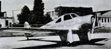
The 1936 Curtiss-Wright Sparrow was an all-metal two place side-by-side cruise, powered by a 90 hp Lambert R-266 engine.
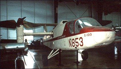
The Curtiss-Wright X-100 was a short-lived research program used to demonstrate the lift concept being developed for the Curtiss-Wright M-200 aircraft, which eventually became the X-19. The X-100 was to test the lift force concept and the gimbaled nacelles needed for a tilt prop configuration, and to test the glass fiber propellers needed to enable the use of radial lift. The X-100 was successful in that it verified the characteristics of the props, and produced data on noise, vibration, downwash, ground effect, stability, and control, and the piloting techniques needed to hover and transition a tilt prop VTOL.
The airframe was all aluminum except for the aft half of the fuselage starting just aft of the cockpit, which was fabric covered. Design and fabrication was completed in just over a year, using concurrent design and construction. The design, fabrication, testing, and documentation of components occurred in a continuous and ongoing process.
The X-100 was a high wing with T-tail and conventional landing gear. The fuselage was 8.6m long and consisted of welded tube construction. The shoulder mounted wing, with a span of 4.9m and an area of 2.1sq.m, had a wing loading of 560kg/sq.m. This was intentional so that the radial force produced by props could be demonstrated beyond any doubt. A three bladed, 3m diameter propeller was mounted on a gimbaled nacelle at each wing tip, and the two props rotated in opposite directions to balance yawing moments. Gross weight was 1580kg. The two-place cockpit had side by side seating. A rectangular engine intake was just behind the cockpit on the top of the fuselage. The T-tail, with an area of 2.1sq.m, was chosen to keep the stabilizer out of the props’ slipstream, giving the X-100 an overall height of 3.28m.
To control pitch and yaw during hover, the engine exhaust was ducted out the rear of the fuselage and could be vectored up or down, and left or right by a device called a jetivator. This device was chosen for simplicity and to reduce weight. As a control effector, the jetivator could produce 63kg of pitch force and 18kg of yaw force. Roll control during hover was by differential control of the prop pitch. Altitude control was by means of the throttle.
The X-100 originally had a rigid conventional landing gear. It eventually was replaced by tricycle gear to improve landing characteristics.
The props were made of foamed plastic molded onto a metal shank and covered with a layer of urethane elastomer. Blades were wide and had a considerable amount of twist to maximize the amount of radial lift. The relatively low tip speed of 200m/s in hover minimized the amount of noise.
The nacelles could rotate from pointing vertical to 12 degrees above horizontal. They rotated forward slowly at 2 degrees per second to allow the pilot to adjust power and attitude in order to prevent settling during the transition to cruise flight. They rotated back to vertical at 5 degrees per second.
Curtiss-Wright’s program managers selected a Lycoming YT-53-L-1 turboshaft engine of either 650 or 825 horsepower. The U.S. Army, who had numerous YT-53-L-1 engines on hand, loaned two of them for the X-100 project. In exchange, Curtiss-Wright agreed to write a report on the engines’ performance. The fuselage had to be enlarged to accommodate the Lycoming engine.
The design process started in February 1958. The first prop assembly was fabricated soon after and tested in NASA’s 12m x 24m wind tunnel starting in October 1958. It was run through the expected power operating range and at shaft angles from 0 to 90 degrees. These tests demonstrated that thrust in hover would be 10 percent below prediction (which was later confirmed in flight test), but there was enough excess thrust that the 10 percent loss was acceptable. Preliminary wind tunnel tests using models were performed at the Massachusetts Institute of Technology, then a powered model was run in the wind tunnel to determine stability and control characteristics. Tests using the actual aircraft eventually were run in NASA’s 12m x 24m wind tunnel. Reasonable correlation was achieved between wind tunnel tests and flight tests.
Roll out of the completed X-100 was on December 22, 1958, at Curtiss-Wright’s Caldwell, NJ, facility, and the first engine run was performed on January 14, 1959. The first hover was made in a tether rig on April 20, 1959, to verify control power and feel. The first free hover test was performed on September 12, 1959, but extra weight was added to prevent the X-100 from getting out of ground effect. After three days of testing, hover flights of up to 20 minutes duration were made. The outflow velocities of air along the ground at various distances from the hovering X-100 proved to be similar to those of a helicopter of similar weight.
Hover proved to be difficult as the pitch and yaw thrust provided by the jetivator was insufficient. Roll and yaw motions tended to couple together. The throttle was used to maintain height during hover, and lags in the engine response further compounded the problem. The X-100 also tended to weathervane into the wind during hover due to yaw moments produced by the wind hitting the props at an angle, which the jetivator’s yaw control could not counter adequately.
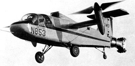
Steady hovering was possible only up to about 4m, while the X-100 was in ground effect. If maximum power was applied on the ground, the X-100 would rise to about 7.6m, settle to within a few feet of the ground, then rise again and repeat several cycles of a slowly damped oscillation in height.
The first transition from hover to forward flight was made on April 13, 1960. The transition itself was fairly simple. The pilot pressed a switch on top of the control stick to rotate the nacelles forward, then added power to prevent sinking. As the nacelles rotated, the X-100 picked up 30km/h of airspeed for each 10 degree of tilt. The conversion was done at 0.9 to 1.5m of altitude and very slowly to prevent settling to the ground. The nacelles were rotated down in 5 degree increments until a speed of 290km/h was achieved with the nacelle at a 15 degrees from horizontal. In general, low speed flight characteristics were unsatisfactory, especially in gusty air. The X-100 demonstrated a high pitch-up moment as forward speed increased, but directional stability, roll control, and longitudinal maneuvering were good in flight at 110km/h. At low altitude and up to 110km/h, the X-100 was notably free of mechanical vibration. Testing at altitude showed the aircraft to be buffet and stall free over a large range of angles of attack.
STOL take-offs and landings were made with nacelle angle at 20 degrees from the vertical. Directional control was poor and was a problem during ground run. Smooth touch-downs also were difficult, much of the problem being caused by the landing gear being too stiff. There was considerable bouncing even at low touchdown speeds.
The basic test program was completed on July 21, 1960. Test pilots from NASA visited Curtiss-Wright and flew the X-100 on August 12 and 13. This concluded test operations for the X-100 at the Caldwell, NJ, facility.
With Curtiss-Wright satisfied that they had proven the radial lift concept, they turned the X-100 over to NASA. It was shipped to the Langley Research Center in October of 1960. It was used to study the effects of downwash on several types of ground surfaces, such as snow, grass, pavement, and packed dirt. NASA also studied problems associated with visibility in snow during hover and slow forward transition. This role was finished by October 1961.
The X-100 was test-flown until August 1965, when a gear case and prop failed. The pilots safely ejected and the ship crashed, but its technology was basis for X-200 and, ultimately, Bell-Boeing XV-22 Osprey.
Following the completion of tests at Langley, the X-100 was donated to the Smithsonian Institution. During its short career, the X-100 completed a total of 14 hours flying time and 220 hours of ground engine run time. It successfully proved the radial force concept, the feasibility of tilting nacelles, and low noise levels.
X-100
Engine: Lycoming YT-53-L-1 turboshaft, 630kW / 825-shp
Wingspan: 7.62m
Length: 8.68m
Height: 3.35m
Empty weight: 1480kg
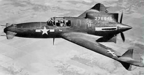
The XP-55 (Curtiss Model 249C), along with the XP-54 and XP-56, resulted from Army Air Corps proposal R-40C calling for unconventional aircraft designs. Like the XP-54, the Ascender was initially designed for the Pratt & Whitney X-1800 engine and had to be redesigned when the engine project was canceled. The XP-55 first flew on 13 July 1943 with an Allison V-1710 engine. It was to be one of the last projects supervised by Donovan Berlin before he left Curtiss to work on the P-75 project for Fisher.
The XP-55 had a pusher engine mounted at rear, swept-back wings and forward canard mountings. The foreplane was not a canard in the true sense, but a free-floating surface with no fixed stabilizer. Its limits were 68 degrees up and down, although the down angle was restricted to 17 degrees for take-offs. Entry to the cockpit was said by test pilots to be rather awkward, requiring a telescoping ladder that was stored behind the pilot’s seat. The XP-55 was essentially a flying wing, having only vestigial vertical surfaces which were distributed on the rear fuselage and outer wings.
The XP-55 was a single-seat single-engine design. The pusher-type engine was mounted to the extreme rear and the wings were highly swept. First drawings and scale models were completed and assessed as early as 1940 to which the Army Air Corps needed more convincing. As a result, Curtiss took it upon itself to produce a flyable full scale model – this one to be designated in-house as the CW-24B. The test aircraft differed some from the final three prototypes developed from the granted contract of 1942. The test bed flew with a Menasco C68-5 powerplant, whereas the final prototype models were fitted each with the Allison V-1710 engine.
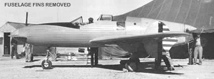
Curtiss built a full-scale flying testbed, the company Model CW-24B, powered by a Menasco C65-5 engine. The fabric-covered CW-24B went to a new US Army test site, the airfield at Muroc Dry Lake, California, for 1942 tests. These revealed serious stability problems which were only partly resolved by moving its vertical fins farther out from their initial mid-way position on the swept-back wing. The Curtiss 24 B was not a true canard, in that it had no fixed forward ‘tail’ surface. Essentially it was a flying wing with a nose mounted elevator. The 24 B made 169 flights from California’s Muroc Dry Lake, but after Curtiss-Wright had validated its concept with the CW-24B flying mock-up the USAAC ordered three XP-55 prototypes, on July 10, 1942. Armament for the XP-55 was originally drawn up to include a pair of 20mm cannon to go along with twin 12.7mm (.50 caliber) machine guns. This arrangement was revisited and revised to a quad .50 caliber array during the testing phase and this standard armament stayed with the life of the program.
For Curtiss, it would be its first design to feature a powered tricycle landing gear assembly (though fixed on the initial test models). The absence of a true rudder resulted in smaller vertical surfaces mounted far off onto the wings. The use of forward canards was also revolutionary as was the ejection system – the propeller had to be jettisoned before the pilot could eject himself. The XP-55 used a single rotation, three-bladed propeller instead of the co-axial, contra-rotating type which had been planned.
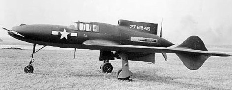
The first XP-55 (42-78845) was completed on July 13, 1943. It made its first test flight on July 19, 1943 from the Army’s Scott Field near the Curtiss-Wright St Louis plant. The aircraft experienced stability problems and underwent several modifications to increase the canard elevator surface, vertical stabilizer area, and eventually received four-foot wing tip extensions to improve stall characteristics. It was found that excessive speed was required in the take-off run before the nose-mounted elevator could become effective. Before this problem could be addressed, the first machine was lost during spin tests at St Louis on 15 November 1943. The first prototype underwent stall testing and on the third attempt the aircraft pitched forward 180 degrees onto its back and fell into the same inverted descent predicted in original Air Corps wind tunnel tests. The engine quit and nothing the pilot did could break the stall. After a perfectly stable fall of 16,000 feet, the pilot, J. Harvey Gray, bailed out safely. The aircraft continued straight down and dug a large smoking hole in the desert floor. After modifications, stall tests were performed satisfactorily, although the complete lack of any warning prior to the stall and the excessive loss of altitude necessary to return to level flight after the stall were undesirable characteristics.
The second XP-55 was flown in St Louis on 9 January 1944. The third followed on 25 April 1944 and, soon after, went to Eglin Field, Florida, for tests of its nose-mounted 12.7mm machine-guns.
The XP-55 had the advantage of being constructed largely from non-strategic materials and for a time a jet version, the company Model CW-24C, was contemplated. But lingering problems, including generally poor stability, remained unsolved when the third XP-55 was returned to Wright Field, Ohio, for further tests continuing into 1945.
An artificial stall warning device was introduced to try and correct some of these problems, and between September 16 and October 2, 1944, the second Ascender underwent official USAAF trials. The trials indicated that the XP-55 had satisfactory handling characteristics during level and climbing flight, but at low speeds and during landings there was a tendency on the part of the pilot to over-control on the elevators because of a lack of any useful “feel”. Pilot, Russ Schleeh, commented that it was terribly unstable, and that if you took your eyes off the horizon for a moment, even in the landing pattern, the plane would drift wildly off course.
The performance of the XP-55 prototype aircraft built (S/N 42-39347, 42-78845-7) was not very impressive and was in fact inferior to that of the more conventional fighters already in service. Performance was mediocre with the Allison V-1710 engine attaining only 377 mph instead of the hoped-for 500 mph. Engine cooling was also a problem. In addition, by 1944, jet-powered fighter aircraft were clearly the wave of the future. Consequently, no production was undertaken, and further development was abandoned. The third prototype survived the testing program, but was destroyed in an accident on May 27, 1945, at Wright Field, Ohio. The pilot, Captain William C. Glascow, came in low over the field during an air show, attempted a barrel roll at low altitude, and crashed. Not only was the aircraft destroyed but the pilot was killed as well as a passing motorist. The sole surviving XP-55 (42-78846) was flow to Warner Robins Field in Georgia in May of 1945. It was later taken to Freeman Field to await transfer to the National Air Museum at the Smithsonian Institution in Washington. Currently the aircraft is in the Kalamazoo Aviation History Museum undergoing a complete restoration.
The second XP-55 has survived and is among numerous historically valuable airframes held by the Smithsonian Institue’s National Air and Space Museum in Washington D.C.
The name Ascender had originated as a joke on the part of a Curtiss engineer, a reference to the aircrafts rather odd design which was not appreciated by the congressional oversight committee. The name stuck, and eventually became official.
Curtiss-Wright XP-55 Ascender
Engine: 1 x Allison V-1710-95 liquid-cooled V12, 1,275hp, 951kW
Length: 29 ft 7 in (9.02 m)
Wingspan: 40 ft 7 in (later 44 ft 6 ft)
Wing area: 209.0 sq ft / 19.41 sq.m later 21.83 sq.m / 234.98 sq ft
Height: 9.84ft (3.00m)
Empty Weight: 6,354lbs (2,882kg)
Maximum Take-Off Weight: 7,710lbs (3,497kg)
Maximum Speed: 390mph (628kmh; 339kts) at 19,300 ft (5,885 m)
Service Ceiling: 34,600ft (10,500m)
Climb to 20,000 ft (6,095 m): 7 minutes 6 seconds
Range: 635 miles (1,022 km)
Armament: 4 x 12.7mm (0.5 in) Colt Browning M2 machine guns in nose
Crew: 1
CW-24B
Engine: Menasco C68-5, 275 hp, 633kW
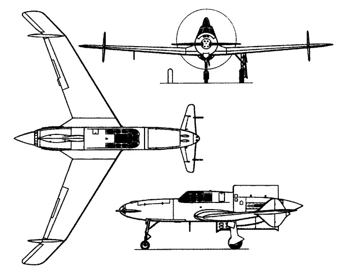
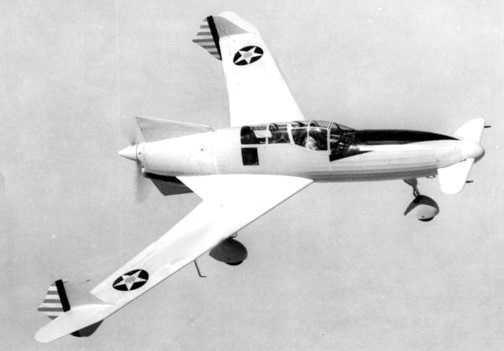
First flown on 2 December 1941, piloted by J Harvey Gray, the sole CW-24B (42-39347) was a low-powered, full-size, flying mock-up of the Curtiss P-55.

CW-24B
Engine: 275hp Menasco C6S-5 pusher
Wing span: 36’7″
Length: 27’4″
Useful load: 826 lb
Seats: 1

