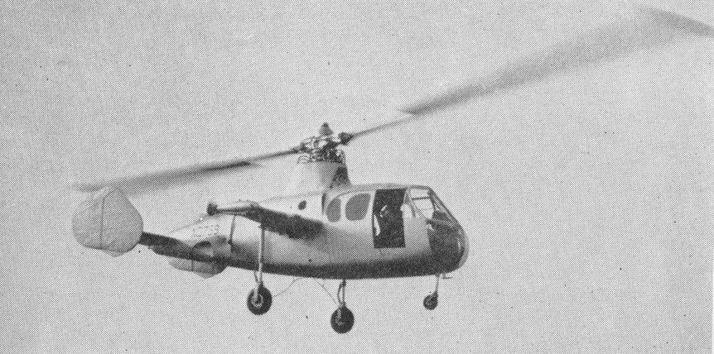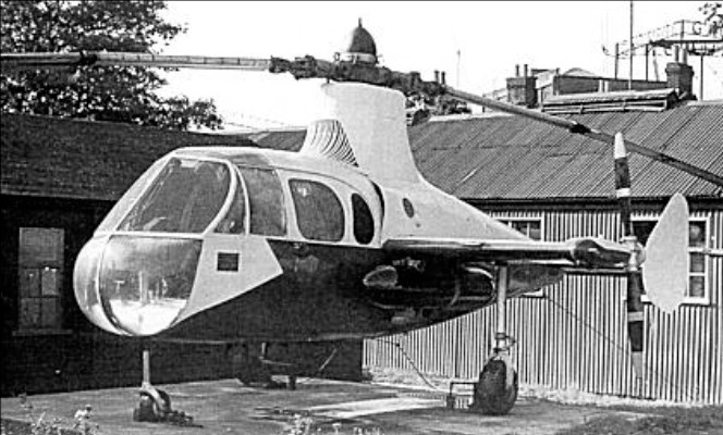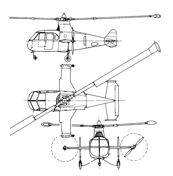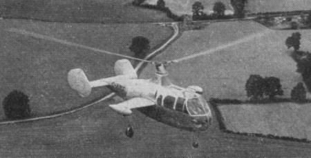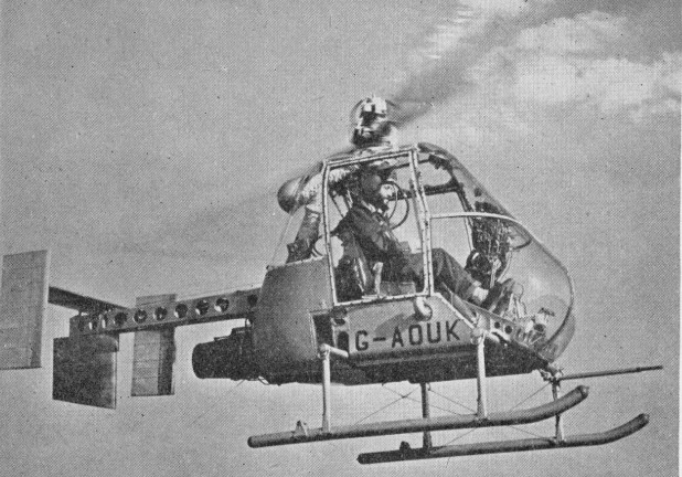
Fairey Ultra-Light Helicopter

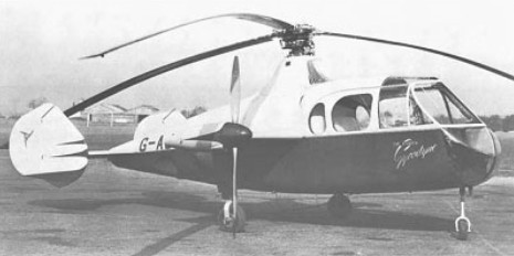
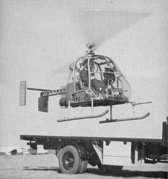
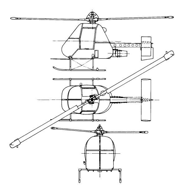
During 1953 the War Office collaborated with the Air Ministry and the Ministry of Supply in the formulation of a specification for a simple and relatively inexpensive small helicopter for use by the Army for reconnaissance and other secondary duties such as casualty evacuation and training. The requirements were severe in terms of vertical climb performance, in tropical as well as temperate conditions, though endurance and speed were less stressed. The helicopter had also to be capable of being dismantled and assembled easily and quickly and of being transported on a standard Army three-ton truck.

The specification was sent to helicopter manufacturers in the British aircraft industry, with requests for tenders, and some half-dozen designs were submitted. Fairey eventually won the contract in July 1954 and a preliminary order for four prototypes, to specification H.144T, was placed. Two more were planned as a private-venture investment.

Fairey believed that a rotor-tip drive would be ideal for the Ultra-light Helicopter (as it was named), and preliminary studies showed that a tip-jet-driven version could be designed to do better than meet the requirements. A suitable small turbojet power source was already available in Britain — the French Turbomeca Palouste BnPe.2, which had been re-engineered with the turbine in Nimonic 90 alloy and was built under licence by Blackburn and General Aircraft.

To provide tip-jet air pressure in addition to residual thrust an oversize centrifugal compressor was fitted, and the excess delivery was bled off from the casing surrounding the annular combustion chamber. Untainted air was thus obtained at an initial maximum pressure of about 2.8kg/sq.cm. With this available pressure it would have been possible to design the rotor for operation using simple air jets, but, with their background of experience of fuel-burning pressure-jets, these were employed.

The compressed air was delivered, via a lagged duct, to the rotor head and, with metered fuel from the same tank as that supplying the gas turbine, and carried by centrifugal force to the tip-jets. There was a manually-operated blow-off valve for use when the engine was being ground-run, and, later in the test development, when rotor-power needed to be cut so that rapid autorotative descents could be made.

With the ample power available the rotor was designed to operate at high revolutions and to have a small diameter (8.53m), thus meeting the need for compactness. Two of the later variants were fitted with a slightly bigger diameter rotor (9.75m) so as to improve the performance. The small diameter of the rotor permitted the mechanical design and control system to be simplified. No drag hinges were employed and the two blades formed a see-saw combination without individual flapping hinges.

A direct tilting-head type of control was employed in the first prototype, but an irreversible hydraulically-powered system for the cyclic-pitch control was designed (together with a flexible pylon) and fitted to this and to later aircraft. The pilot’s controls were those normal for helicopters — with a collective-pitch lever which carried a twist-grip throttle for increasing engine revolutions and consequent air pressure for the tip-jets, and a stick for control in roll and pitch, but the rudder-pedal directional control was through a steel-skinned rudder on which the jet efflux impinged.

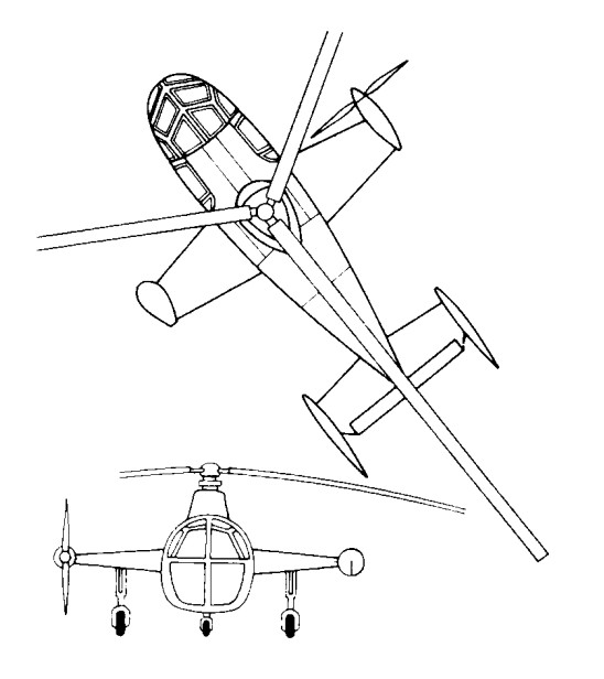
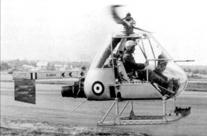
The Ultra-light was very simple in construction, the basis of which was a large light-alloy box containing the bag-type fuel tank. From the centre of this box rose the rotor pylon on which the remainder of the aircraft was, so to speak, hung. To the rear was attached a box-girder boom, under which the engine was slung, carrying the rudder — or rudders and an adjustable tailplane in later versions. This boom had a transport joint aft of the engine mounting. The crew’s seats (the observer facing aft in the proposed Army version) were on the basic box structure. The undercarriage consisted of a pair of skids attached to tubes running across the underside of the box.
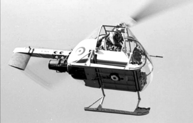
The initial flight of the first prototype, XJ924 (F.9423), was made at White Waltham by W. R. Gellatly, on 14 August, 1955 – only about 13 months from the start of design work — and it was shown and flown at the SBAC exhibition and display at Farnborough early in the following month.

Progress on the original basis was, however, to be overtaken by events. Before mid-1956 the Ministry of Supply had, for reasons of economy, ceased to support the Army project, and development of the Ultra-light was continued by Fairey on a private-venture basis, with considerable and expensive efforts to develop the original design and to sell it to prospective Service and civil operators.

There have been some considerable differences, among semi-official and other records, of the actual identities of the various Ultra-lights, of the total number completed and of the sequence in which they were produced. The principal difficulty in straightening the records has been caused by the fact that the original order ‘bookings’ were changed. Four (F.9423—9426) were planned to meet the original Ministry of Supply contract and two more (F.9427—8) were built by Fairey on a private-venture basis. After a certain amount of work had been done there were interchanges of components and then, following the Ministry cancellation, Fairey increased their private-venture programme.

Some uncertain confirmation of the sequence of the completion of the Ultra-lights can be found in the press reports of the SBAC displays of the period. One such report for 1956 said that four had by then been built, the fourth being G-AOUK; another, after the 1957 display, said that five had been built, including G-AOUJ, which was at the show with G-AOUK, and that a sixth, G-APJJ, was under construction.

The serials XJ924, 928, 930 and 936 were allotted to the first four and three of the six were civil-registered following the withdrawal of official support. In order of c/ns, but not necessarily of completion or of initial flights, the six appear to have consisted of the following individual aircraft. The first prototype, XJ924 (F.9423), was the first to fly and was later modified with the hydraulic cyclic-pitch control and flexible pylon already mentioned. The second prototype, XJ928 (F.9424), became a Fairey de velopment aircraft for which a modified cabin was designed so that different loads, such as a stretcher case, could be accommodated; this was registered G-AOUJ and fitted with the hydraulic controls, flying for the first time in the revised form on 1 September, 1957. The third prototype, XJ930 (F.9425), was delivered to the Ministry of Supply. The fourth, XJ936 (F.9426), flown on 24 August, 1956, was the first to be fitted with the hydraulic controls and the flexible pylon; it appeared at die SBAC Display in September 1956 registered G-AOUK, and was the company’s principal demonstration and trials aircraft. Operating from the back of a standard truck, it demonstrated a rate of climb of 6.75m/s and a rate of descent in autorotation of 20m/s. The first of the two original private-venture aircraft, F.9427, was apparently used only for resonance tests and for ground-transport trials.

In the autumn of 1957 G-AOUJ underwent trials aboard the frigate HMS Grenville to determine the practicability or otherwise of operating small reconnaissance helicopters from platforms at sea. More than 70 landings and take-offs were made in winds of up to 62 knots, with the deck sometimes pitching through 3.05-3.66m and rolling up to 14 degrees each way. During 1958 both G-AOUJ and G-APJJ were being evaluated by the Royal Navy. The second, F.9428, was registered G-APJJ and flown initially in 1958; this had a cabin similar to that of G-AOUJ and was used for trials by the Royal Navy, operating from the deck of a destroyer, HMS Undaunted, before going to the Royal Aircraft Establishment, Bedford, and later to the College of Aeronautics at Cranfield.

In 1957 the Piasecki Aircraft Corporation of Philadelphia, USA, had obtained an option to build and the US Army was evaluating it for uses similar to those originally envisaged by the British authorities. Nothing, however, was to follow from these developments.
Typical of the continuous effort being put into Ultra-light demonstrations was the use, early in October 1958, of the stretcher-carrying G-AOUJ, flown by Peter Twiss, in a nuclear-war casualty exercise by the RAMC near Aldershot; the Rotodyne also took part in this exercise. Interest in the Ultra-light had been shown in Canada, and G-AOUJ, with its bulged nose to take a stretcher, and with special navigation and heating/ventilating equipment, was shipped out there later in 1958 for cold-weather trials and demonstrations by Lt-Cdr J. G. P. Morton. In the spring of that year a new draft specification was being drawn up for a version suitable for operation from small ships on anti-submarine duties both in attack (with a homing weapon) and communication roles. This proposal was based on a draft naval staff requirement and was a variation of the aircraft described in a brochure of April 1957 in which a naval strike version had been offered. The three civil-registered Ultra-lights were necessarily designed to meet airworthiness requirements and G-AOUJ and G-APJJ were duly certificated in the autumn of 1958. Work on the project was finally abandoned in 1959.

G-AOUJ has returned to the Helicopter Museum and restoration continued at Weston super Mare, but various parts, and drawings, are missing. A particular problem now is the swash-plate mechanism, of which there are no details.
Gallery

Engine: 1 x Turbomeca Palouste turboshaft, 185kW
Main rotor diameter: 8.61m
Fuselage length: 4.57m
Max take-off weight: 817kg
Empty weight: 290kg
Max speed: 153km/h
Hovering ceiling, IGE: 3109m
Range: 300km
Fairey Jet Gyrodyne

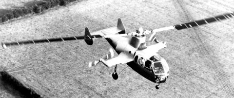
Towards the end of 1953 the surviving second prototype Gyrodyne reappeared in a very different form. A research contract had been received from the Ministry of Supply to try the principles of the tip-jet rotor-driving system.

This was necessary to test the tip-jet, and to develop handling and other procedures for the compound, or convertible, helicopter. By early January 1954 this aircraft, named the Jet Gyrodyne, and carrying the duplicated Ministry serial XD759, which was later to be changed to XJ389, was making tethered flights at White Waltham in the hands of John N. Dennis, who had joined Fairey as helicopter test pilot in June 1949. The first free flight was made in January 1950.

The Jet Gyrodyne retained the fuselage, tail unit, stub wings and tricycle undercarriage of the Gyrodyne, and was also powered by a specially modified Alvis Leonides nine-cylinder radial. The engine was used to drive, through a gearbox and shafts in the stub-wings, two variable-pitch pusher propellers of Fairey design. These propellers provided propulsion in cruising flight and slow-speed directional control through rudder pedals by means of a differential pitch-change which was superimposed on the collective-pitch action. A third drive from the Leonides was taken from the main gearbox, via a friction clutch, to two Rolls-Royce Merlin centrifugal compressors mounted face-to-face under the rotor pylon. Air from these compressors was fed to the fuel-burning pressure-jet units at the tips of the 18.29m two-blade rotor. Unlike that of the Gyrodyne, the rotor had a conventional helicopter control system – with collective-pitch change for varying the overall lift, and cyclic alterations of the blade-angle, by means of a conventional column, to provide fore-and-aft and lateral, or rolling, control.

In the Jet Gyrodyne tip burners, compressed-air from the blowers passed through the rotor blades, while centrifugal force fed the metered fuel through the blades to the jets. The compound, or convertible, helicopter principle is lift for take-off, slow flight and landing was provided by the jet-driven rotor. For transition to cruising flight the compressed air to the rotor tips was progressively reduced and available engine power transferred to the propellers, leaving the rotor as an auto-rotating lift unit which was supplemented (in a very minor proportion for the Jet Gyrodyne) by the fixed wing. The procedure was reversed for a return to the helicopter regime.

The problem for the Jet Gyrodyne was accentuated by, at a gross weight of 2720kg, under-powered for the work it had to perform and the Leonides was normally operated at maximum boost. The Jet Gyrodyne could not quite maintain level flight in the cruising, autorotative, mode. It was not until 1 March, 1955, that a transition was completed by John Dennis. Within four months of this first full transition, the techniques had become well established and transition was no longer being accompanied by a considerable loss of height. The cycle was demonstrated during the SBAC Display at Farnborough in September 1955; while practicing for this demonstration, 65 successful in-flight tip-jet re-lights were accomplished during eight days.

Even during the earlier period of testing, the transition from helicopter to autogyro flight was relatively easy. The basis of the operation was the transfer of engine power from the jet-feeding compressors to the propellers. The pitch of the propellers was progressively coarsened, thus absorbing more power and reducing the air delivery to the jets, which eventually flamed out, and the compressors were declutched. It was found that transition could be made at widely varying speeds, but 128km/h was found to be the most convenient, with a rotor speed of about 210 rpm.

The difficult operation was the transition back to helicopter flight. A great deal of flying was required before the best propeller-pitch and tip-jet re-lighting sequence could be established. A major part of the difficulty was that, with the compressors being driven, there was no reserve of engine power for the propellers during the re-lighting sequence, and the aircraft descended rapidly in autorotation until the jets had been re-lit. So long as the re-lighting was being done over or near an aerodrome there was no particular danger in this situation; a controlled landing could be made, and often was made, in autorotation.

As finally established, the drill was to throttle back momentarily, engage the compressor clutch, switch on the tip-jet ignition and fuel supply, and progressively fine-off the propeller pitch. This automatically opened the intake-valves for the compressors. The tip-jets re-lit when a certain head pressure had been reached and collective-pitch was increased to keep the rotor speed down. Propeller pitch was then slowly reduced to zero so that maximum power was available for the blowers to give full tip-jet thrust.

Because of the need to keep the gross weight down with the limited power available, the Jet Gyrodyne normally carried only sufficient fuel for 15 minutes or so of safe tip-jet burning endurance. Extra tanks were occasionally carried under the wings to provide 30 minutes’ endurance, but, as already noted, there was no particular danger in fuel exhaustion for an aircraft which could make powerless autorotative landings from a best indicated gliding speed of only 72km/h. The high inertia of the big rotor allowed for a few moments of hovering before touch-down.

By September 1956 the Jet Gyrodyne had made 190 transitions and 140 autorotative landings. The techniques were by then familiar and reasonably well understood, so that there was already a sound basis for the procedures required for the Rotodyne, which was to make its first flight a year later.

All the early test flying with the Jet Gyrodyne, including transition from helicopter to autogyro flight and vice versa in March 1955, was done by John N. Dennis. Six Ministry of Supply pilots each flew the Jet Gyrodyne successfully after about an hour’s instruction and practice.

At the time when the Jet Gyrodyne was making its earlier test flights the design team was led by Dr G. S. Hislop, chief designer (helicopters), and Capt A. G. Forsyth, chief helicopter engineer, who was responsible, among other features, for the tip-jets, and shared with Dr J. A. J. Bennett (who had by then left the company) the 1949 British Patent on which the Jet Gyrodyne and Rotodyne concepts were based. Later Jet Gyrodyne flight development was carried out by Sqn Ldr W. R. Gellatly and Lt Cdr J. G. P. Morton, who were to take the Rotodyne through its four years of testing.

Although scheduled for scrapping in 1961, the Jet Gyrodyne was rescued and eventually preserved.

Fairey Gyrodyne / E.4/46 / FB-1 / Fairey-Bennett One

In preparation for the move into rotary-wing development, Fairey had built up a strong helicopter team, led by Dr J. A. J. Bennett, who brought the Gyrodyne proposal to the company in August 1945, and with Sqn Ldr Basil H. Arkell, who joined in January 1946, as test pilot. The first official announcement of the project, a private-venture to specification E.4/46, was made on 3 April, 1946, though no information was then given; at that time the Gyrodyne was known as the FB-1 (Fairey-Bennett One).

Although the broad concept was relatively simple, the translation of this concept into working hardware involved a considerable effort in engineering and other ingenuities. An idea of the amount of ‘machinery’ in the prototype can be gathered from the fact that nearly 50 per cent of the empty weight was contributed by the powerplant and transmission systems. In these there were four primary units: a 520hp Alvis Leonides nine-cylinder radial engine, with its mounting and systems; a main gearbox with first-stage reduction for the rotor and propeller drives, a clutch and freewheel; an upper gearbox with double epicyclic reduction gear, plus the rotor brake; and a gearbox in the starboard wingtip with the reduction-gear and pitch-changing mechanism for the propeller.

The engine power could be transmitted in variable ratios to a three-blade rotor just over 15m in diameter and to the anti-torque propeller on the starboard tip of the stub wing, the Gyrodyne behaved like a helicopter, but the same propeller also provided the necessary thrust for fast flight, when the aircraft looked almost like an autogyro.

The rotor articulation was designed so that the collective-pitch changed automatically according to the power being applied. The throttle lever was designed to be similar in length, movement and effect to the collective-pitch control of a conventional helicopter and was pulled up to increase power and lift. Fore-and-aft and lateral control was provided by a form of tilting head; although the rotor-hub axis did not physically tilt, as in the case of most autogyros, a similar effect was produced by tilting the rotor head in relation to the axis. Stick-shake was eliminated, using suitable safeguards, by controlling rotor-tilt through irreversible hydraulic jacks.

The Ministry of Supply asked for an alternative rotor-hub arrangement to be designed with overriding collective-pitch and cyclic-pitch blade-angle control so that this could be compared on test with the existing system. This normal helicopter control system was required mainly for trimming purposes at altitude and to provide more positive control when hovering after an autorotative approach.

Yaw control was maintained, as with other helicopters, by altering the pitch of the propeller through conventional pedals. Rudders were fitted for directional control during autorotative flight after power failure. An ‘elevator’ in the form of a large trim tab, was used to adjust the fuselage attitude when cruising.

A government contract to Specification E.4/46 was awarded for two prototypes, and the first Fairey Gyrodyne, G-AIKF (provisionally serialled VX591), was exhibited almost complete at White Waltham on 7 December 1946.

After 85 engine-running and 56 rotor-testing hours the first untethered flight was made at White Waltham by Basil Arkell on 7 December 1947, weighing just over 2000kg. Testing continued, with longer flights at gradually increasing speeds, until March 1948, when the Gyrodyne was dismantled for examination. By then a second prototype, G-AJJP, had been completed.

The second prototype, basically similar to the first but with more comfortable interior furnishings befitting its role as a passenger demonstrator, was flying by the time of the next SBAC Display, in September 1948, at Farnborough.

Following re-assembly and further tests, G-AIKF was prepared for an attempt on the international helicopter (Class G) speed record in a straight line. This had long been held unofficially by the German Focke Achgelis Fa 61 and more recently a Sikorsky R-5 had also been unofficially timed at 185km/h in the USA. Two eastward and two westward flights over a 3km course at White Waltham were made by Arkell on 28 June, 1948, at an average speed, for the best pair of opposing runs, of 200km/h. In addition to being a world record, this was the first British national record for any helicopter. The course was along the London-Reading railway line on the north side of the aerodrome, and, as it happened, was 45 degrees off a fairly strong wind, so the probability is that a speed of 225km/h might have been achieved in calmer conditions.

Some ten months later an attempt to set up a 100km closed-circuit record ended in tragedy. During trials on 17 April, 1949, two days before the attempt was to be made, the first prototype Gyrodyne suffered a fatigue failure in the rotor head and crashed at Ufton, near Reading, killing F. H. Dixon and his flight observer, Derek Garroway. Dixon, who joined Fairey in 1936 and was chief test pilot from 1942 to 1945, had since been involved in less arduous flying and other duties, but had also shared much of the development and demonstration flying of the Gyrodyne with Basil Arkell.
The investigation following the accident led to a protracted period of investigation and fatigue-testing, and development ceased. The second prototype was grounded and was afterwards very much modified to reappear more than four years later as the Jet Gyrodyne, the test vehicle for the Rotodyne.

Gallery

Engine: 1 x Alvis Leonides, 388kW
Main rotor diameter: 15.77m
Fuselage length: 7.62m
Height: 3.10m
Take-off weight: 2177kg
Empty weight: 1633kg
Max speed: 124 mph
Seats: 4-5

Fairey Firefly

Firefly FR .Mk4

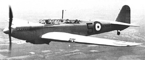
A natural development of the Fulmar two seat fighter, the Firefly was designed by a team led by H E Chaplin to meet specification N.5/40, an amalgamation of the earlier requirements of N.8/39 and N.9/39 which had called for a carrier based fighter with a turret. However, the turret was dropped, and when chief test pilot Chris Staniland flew the first Firefly I on December 22, 1941, it was a clean tandem-seater with manually folding wings containing four 20 mm (0.79 in) cannon and retractable Youngman area increasing flaps. At first there was no requirement for the type to be able to carry bombs or rockets.

Fairey Firefly Article

It was a stressed skin monoplane with folding elliptical wings housing four cannon and with the trailing edge with Youngman flaps which could be recessed into the wing.

Full production started in August 1942 with the first production F.I flying on 26 August 1942.

Development was satisfactory, and the F.1, with 1730 hp / 1,483kW Rolls Royce Griffon IIB driving a Rotol three-bladed propeller, entered service with 1770 Squadron of the Fleet Air Arm in October 1943 as a two-seat day fighter, subsequently seeing extensive action in all theatres, especially in air to surface attacks against the Japanese. Manoeuvrability and long range made up for poor speed, and the good pilot view and comfortable rear observer cockpit were most welcome. Fairey, at Hayes and Stockport, and General Aircraft built 429 F.Is followed by 376 FR.Is (fighter reconnaissance) with ASH ship and submarine ¬detection radar in a radome under the nose of the fuselage. Each was armed with two 20mm cannon in each wing. Then followed 37 NF.II night fighters, with the large AI.X radar packaged into pods on the leading edge of both wings and with the forward fuselage lengthened to preserve centre of gravity posi¬tion, which was disturbed by the heavy displays in the rear cockpit. Conversions included the NF.I, with American 3 cm AI radar (usually APS 6) in a ventral pod, with other changes including shrouded exhausts, and the FR.IA which was a Mk.I rebuilt almost to FR.1 standard. From the 471st aircraft the engine was the 1990 hp Griffon XII.

The Firefly T.1 was basically an F.1 converted for use as a deck-landing conversion and instrument-flying trainer. The raised rear cockpit was occupied by the instructor. They were usually unarmed, although a few carried two 20mm cannon.

RCN Firefly T.1

The Firefly T.2 was an armaments trainer, similar to the T.1 with two 20mm cannon and provision for carrying bombs, rockets and long-range drop tanks. The Griffon 12-powered Firefly T.3 was a version of the FR.1 intended specifically to train observers, the rear cockpit being equipped with the fullest possible range of radio and radar equipment.

Not¬able highlights included the attack on the German battleship Tirpitz and a series of strikes on mainland Japan shortly before VJ-Day brought hostilities to a conclusion. In the post-war era, the Firefly demonstrated a considerable degree of versatility, turning its hand to other duties such as target towing and anti-submarine warfare as well as continuing in its primary function of fighter-bomber. By the time production ceased 1,702 had been built, some remaining active with the Fleet Air Arm until as late as 1957 whilst others served with Australia, Canada, Denmark, Ethiopia, India, the Netherlands, Sweden and Thailand.

Indian Air Force Firefly Mk.1 target tug

The Royal Canadian Navy employed 65 Fireflies of the Mk AS5 variety on board its own aircraft carriers between 1946 and 1954. The letters ‘AS’ stand for anti-submarine, which was the intended primary role of the RCN’s Fireflies.

Firefly AS.5

A total of 29 Firefly FR.1s were operated by the RCN after the war.
Availability of the two stage Griffon led to the F.III, reaching 562 km/h (349 mph) with the 2035 hp Griffon 61, but handling was poor.
An extensive redesign resulted in the greatly improved F.IV (postwar FR.4) with 2250 hp Griffon 74 driving a four blade Rotol propeller, which flew for the first time on 25 May 1945. New square tipped wings had reduced span and neat leading edge pods housing fuel (left) and radar (right). Radiators were moved to the inboard leading edge, the area of the tailfin was increased, and the aerodynamics improved. New underwing racks could carry up to 907 kg (2000 lb) of bombs, 16 rockets or drop tanks. Production, all by Fairey, amounted to 160 were completed by early 1948, of which 40 went to the Royal Netherlands Navy. Nearly all those in front line service with Royal Navy carriers saw action in Korea in 1950 53.
Some later being modified to Firefly TT.Mk 4 standard for target-towing duty.
The next basic model to appear was the Mk 5. Similar to the 4, but with the wing folding and locking powered hydraulically, and with additional role equipment. Variants including the Firefly NF.Mk 5 night-fighter, the Firefly FR.5 day reconnaissance fighter and the Firefly AS.Mk 5 antisubmarine patrol aircraft; the last eventually became the most numerous post-war version. All had better communications, navigation and IFF, and the NF and AS having night and search/attack radar. Production totalled 352 between 1947 and 1950, including batches for the Royal Australian and Canadian Navies which served throughout the Korean campaign.
The FR.5 carried the same radar in the starboard wing nacelle as the 4 and was equipped with beam approach, IFF and communications radio. The NF.5 had the same basic radio plus a radio altimeter and other night-flying equipment. The AS.5 was an anti-submarine version and carried special submarine-detection equipment under the wings and fuselage.
In 1951, the Firefly AS.6 entered service as an interim ASW aircraft pending delivery of the Fairey Gannet. It abandoned all fighter pretensions and carried only radar, sonobuoys and antisubmarine weapons. Fairey built 133.
The Firefly 7 of 1953 was produced in two forms, as the AS and T, although it was used mainly as an anti-submarine training aircraft. Powered by a Griffon engine with a ‘chin’ radiator, the three-seat anti-submarine aircraft carried the latest detection devices and sonobuoys for tracking a target at sea. A new blister-enclosed rear cockpit accommodated two radar operators and the aircraft had elliptical long span wings without wing radiators, swept forward wing roots, and a new tail unit.

Firefly U.9

The remaining 160 Mk 7s were all Firefly T.Mk 7 trainers. Firefly production eventually terminated in March 1956 with the delivery of the last of 24 new-build Firefly U.Mk 8 target drones, but 54 Mk 5s were also converted to this mission, these being known as Firefly U.Mk 9 aircraft. The U.8, U.9 and U.10 were all radio controlled drones or targets. The Fairey Firefly 8 (Rolls Royce Griffon 59) had four cameras in each wing tip fairing to photograph missiles which are directed to its vicinity. For test purposes and other duties it may be flown by a crew of two pilot and observer. Unlike the Firefly 7, from which it was developed, has an arrester hook fitted in the aperture under the fuselage. This is for arrested landings on aerodromes while under radio control. It has an 86 gallon fuel tank between the cockpits. The U.9 was the standard target for development and training with the Seaslug ship to air missile, while the U.10 was a similar rebuild of the AS.7.

Firefly 9

All targets had large multi angle high speed camera pods on the wingtips.

In the 1950s more than 450 Fireflys were rebuilt for new roles. The first was the TT.1 target tug, with Mk 2B windmill winch and 2150 m (7053 ft) of cable for a drogue target; some of these had a long career in Sweden. The T.1 operational trainer, 30 of which were supplied to the Royal Navy and a few to other countries, had two separate stepped cockpit canopies, dual control and changed equipment. Most were unarmed, but some had two cannon.
Operationally, British Fireflies of various marks saw considerable post-war action, taking part in the Malayan confrontation between 1949 and 1954 as well as the Korean War, whilst the Dutch Firefly FR.Mk 1 aircraft undertook combat duty against rebel forces in the Dutch East Indies.
In total, 1623 Fireflies left the assembly lines.

Gallery

Firefly F.I
c/n 1-470
Engine: Rolls-Royce Griffon IIB, 1730 hp
Wingspan: 44 ft 6 in / 13.56 m
Wing area: 327.979 sq.ft / 30.47 sq.m
Length: 37 ft 7 in / 11.4 m
Height: 13 ft 7 in / 4.15 m
Empty weight: 9750 lb / 4422 kg
Loaded weight: 14,020 lb / 6359 kg
Wing loading: 42.85 lb/sq.ft / 209.0 kg/sq.m
Max speed: 316 mph / 509 kph / 275 kts
ROC: 1700 fpm / 518 m/min
Service ceiling: 28,000 ft / 8534 m
Range internal fuel: 580 mi / 933 km
Range w/max.fuel: 1720 km / 1069 miles
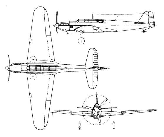
Armament: 4 x 20mm Hispano cannon
Bombload: 2000 lb / 906 kg
Crew: 2

Firefly I
c/n 471-
Engine: Rolls-Royce Griffon XII, 1990 hp
Wingspan: 44 ft 6 in / 13.56 m
Length: 37 ft 7 in / 11.4 m
Height: 13 ft 7 in / 4.15 m
Empty weight: 9750 lb / 4422 kg
Loaded weight: 14,020 lb / 6359 kg
Max speed: 316 mph / 509 kph
ROC: 1700 fpm / 518 m/min
Service ceiling: 28,000 ft / 8534 m
Range internal fuel: 580 mi / 933 km
Armament: 4 x 20mm Hispano cannon
Bombload: 2000 lb / 906 kg

Firefly II
Wingspan: 44 ft 6 in / 13.56 m
Length: 37 ft 7 in / 11.4 m
Height: 13 ft 7 in / 4.15 m

Firefly III
Wingspan: 44 ft 6 in / 13.56 m
Length: 37 ft 7 in / 11.4 m
Height: 13 ft 7 in / 4.15 m

Firefly FR.Mk 4
Engine: one 2,245-hp (1674-kW) Rolls-Royce Griffon 74
Wingspan 12.55 m (41 ft 2 in)
Wing area 30.66sq.m (330 sq ft)
Length 11.58 m (38 ft 0 in)
Height 4.24 m (l3ft 11 in)
Empty weight: 4388 kg (9,674 lb)
Loaded weight clean: 13,927 lb / 6317 kg
Maximum take-off: 7083 kg (15,615 lb)
Maximum speed: 591 km/h (367 mph) at 4265 m (14,000 ft)
ROC: 2050 fpm / 625 m/min
Service ceiling 9725 m (31,900 ft)
Range internal fuel: 760 mi / 1223 km
Range max: 2148 km (1,335 miles)
Armament: four 20-mm Hispano cannon
Bombload: 16 27-kg (60-lb) rockets or two 454-kg (l,000-lb) bombs.

AS.5
Engine One 2,259hp Rolls Royce Griffon 74
Wing span: 12.55 m (41 ft 2 in)
Length: 11.56 m (37 ft 11 in)
Height: 14 ft 4 in
Empty weight 9,674 lb
Gross weight: 7300 kg (16100 lb)
Maximum speed: 618 km/h (384 mph)
Initial Rate of Climb: 6 mins 50 secs to 10,000 ft
Ceiling: 28,400 ft
Endurance: 6.5 hours
Armament: 4 x 20 mm cannon Hispano
Bombload: 2 x 1,000 lb bombs or 16 x 60 lb rockets
Crew 2

Firefly Mk. 6 ASR
Engine: Rolls-Royce Griffon 74, 2245 hp
Wing Span: 41ft (12.50m)
Length: 37ft (11.28m)
Height: 15ft 6in(4.7m)
Range: 1,070 miles(1,772 km) w/ 2 @ 90Imp.Gal drop tanks
Speed: 345 mph (555 km/h)
Armament: two or four 20mm canon two drop tanks or ASR equipment
Bombload: 3000 lb / 1359 kg

Firefly 7
Engine: Rolls-Royce Griffon 74, 1145 hp
Wingspan: 44 ft 6 in / 13.56 m
Length: 38 ft 3 in / 11.65 m
Height: 14 ft 4 in / 4.37 m
Empty weight: 11,016 lb / 4997 kg
Loaded weight: 13,970 lb / 6337 kg
Bombload: 3000 lb / 1359 kg

Firefly 8
Engine: Rolls-Royce Griffon
Span: 43 ft 6 in
Length: 38 ft 3 in

FR.5

Fairey Spearfish

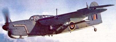
The Spearfish was designed by Fairey Aviation to Admiralty Specification O.5/43 as a replacement for the Fairey Barracuda in the carrier-based torpedo/dive bomber role. In comparison to the Barracuda, the Spearfish had a much more powerful engine, an internal weapons bay and a retractable ASV Mk.XV surface-search radar mounted behind the bomb bay. The Spearfish was half as large again as the Barracuda, as it was designed to be operated from the 45,000-long-ton (46,000 t) Malta-class aircraft carriers then under development.

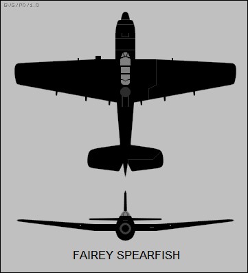
The Spearfish was a cantilever, mid-wing monoplane, with an all-metal, monocoque fuselage. The centre wing section was built integral with the fuselage and the outer wing panels could be hydraulically folded for carrier operations. A distinguishing feature of the wing was the large Fairey-Youngman flaps that spanned 73.5% of the wing’s trailing edge. The Spearfish had an outward-retracting conventional landing gear with a tailwheel. The wings housed a pair of 183-imperial-gallon (830 l; 220 US gal) fuel tanks, plus a 43-imperial-gallon (200 l; 52 US gal) tank in the leading edge of the starboard wing for a total of 409 imperial gallons (1,860 l; 491 US gal) of fuel. The two-man tandem cockpit had a hydraulically operated canopy.

The large internal weapons bay could alternatively carry up to four 500-pound (230 kg) bombs, four depth charges, a torpedo, or a 180-imperial-gallon (820 l; 220 US gal) auxiliary fuel tank. The Spearfish was intended to carry four 0.5-inch (12.7 mm) M2 Browning machine guns, two in a remote-controlled Fraser-Nash FN 95 barbette behind the cockpit and two in the wings. The only external offensive armament was 16 RP-3 rockets that could be carried underneath the outer wing panels.

In August 1943, the company received an order for three prototypes to be built against Specification O.5/43 and the first prototype, serial number RA356, was constructed at Fairey’s Hayes factory and first flew on 5 July 1945 from Heston Aerodrome; the other two did not fly until 1947. In November 1943 the company was ordered to build a dual-control dive-bombing trainer variant against Specification T.21/43 and this was built at the Heaton Chapel factory and assembled and flown at Ringway on 20 June 1946. Three further development aircraft were ordered in May 1944 to be built at Heaton Chapel, with the last two to be fitted with a Rolls-Royce Pennine engine; only the first Centarus-engined aircraft was built but never flew.

Production orders for 150 aircraft were placed to be built at Heaton Chapel; the first ten aircraft were intended to use 2,600-horsepower (1,900 kW) Bristol Centaurus radial engine, Centaurus 59 engines on the next 22, and Centaurus 60s of the remainder. In addition, the flaps were to be enlarged and lateral control was to be provided by spoilers with small “feeler” ailerons. With the cancellation of the Malta-class carriers, the Fleet Air Arm no longer had a requirement for new torpedo bombers and the programme was cancelled. Work continued on the two other prototypes built at Hayes after the cancellation of the contract, albeit very slowly.

Test pilot Eric Brown evaluated the first prototype and found “the controls in cruising flight were very heavy and, in fact, lateral control was so solid that I could barely move the ailerons with one hand at 130 knots (240 km/h; 150 mph).” In bad weather a pilot circling a carrier while waiting to land would have been forced to fly such a wide circuit that he could not always keep the carrier in sight. The later prototypes had ailerons boosted by hydraulic power and artificial feel to the stick from a spring, as an interim measure but Brown found “the second prototype was much less the pleasant aircraft to fly as the stick continually hunted either side of neutral and there was no build-up of stick force with increase in speed.” The Spearfish lacked any sort of stall warning, which would have been a problem in operational use as the stall and approach speeds were fairly close. For the landing, the aircraft proved quite docile.

The first prototype was later used by Napier & Son at Luton for trials of the firm’s inflight de-icing systems. It was then briefly used for ground-training purposes beginning on 30 April 1952, until it was scrapped shortly afterwards. The second prototype was used by the Royal Navy Carrier Trials Unit at RNAS Ford, Sussex, until it was sold for scrap on 15 September. The third prototype conducted ASV Mk.XV radar trials, but was damaged in a heavy landing on 1 September 1949 and sold for scrap on 22 August 1950 as uneconomical to repair. The fourth prototype never flew and was used as a source of spares. The sole Heaton Chapel-built aircraft was the closest to the planned production configuration and it was used for engine-cooling and power-assisted flying-control trials, until it was struck off charge on 24 July 1951.

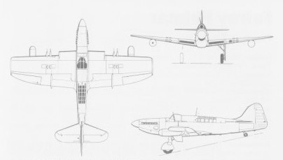
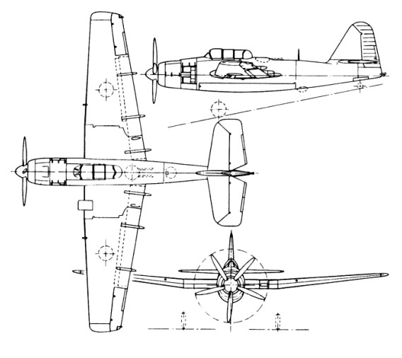
In a follow-up, to meet Specification O.21/44 for a two-seat strike fighter, the Spearfish was redesigned to accommodate a twin-coupled Rolls-Royce Merlin engine and contra-rotating propellers. A variety of other engines were considered and although a production order was placed for three examples in 1944, the programme was eventually shelved, remaining as an unfulfilled paper project.

Engine: 1 x Bristol Centaurus 57, 2,825 hp (2,107 kW)
Propeller: 5-bladed Rotol VH 65, 14 ft (4.3 m) diameter
Wingspan: 18.36 m / 60 ft 3 in
Wing area: 49.24 sq.m / 530.01 sq ft
Length: 13.59 m / 44 ft 7 in
Height: 4.11 m / 13 ft 6 in
Max take-off weight: 10026 kg / 22104 lb
Empty weight: 6901 kg / 15214 lb
Fuel capacity: 409 imperial gallons (1,860 l; 491 US gal)
Max. speed: 470 km/h / 292 mph / 254 kn
Cruise speed: 196 mph (315 km/h, 170 kn)
Service ceiling: 7620 m / 25000 ft
Time to 10,000 ft / 3,048 m: 7.75 min
Range: 1,036 mi / 1,667 km / 900 nmi
Combat range: 349 mi (562 km, 303 nmi)
Armament: 4 x 12.7mm M2 Browning machine guns
Bombload: 1 × torpedo or 2,000 lb (907 kg)
Crew: 2

Fairey Barracuda

The original S.24/37 Barracuda was designed around the Rolls-Royce Exe 24-cylinder X-type engine but early in the construction stage the power plant was changed to the Rolls-Royce Merlin 30. This Merlin-engined prototype first flew on 7 December 1940.
The first prototype Barracuda had an unbraced tailplane in line with the top of the fuselage but during the early trials it was found that when the flaps were in the diving position the disturbed air caused serious tail flutter. To overcome this the tailplane of the second prototype was raised 1.22m to clear the wake from the flaps and also to clear the folding wings. The first trials with the repositioned tail unit were made in July 1941 and eliminated the problem.
The Barracuda was first used operationally in September 1941 in raids from HMS Victorious on Kirkenes in northern Norway and on Petsamo in Finland. The first monoplane torpedo bomber to go into service with the FAA. In 1942 Barracudas took part in sweeps over French ports and in the invasion of Madagascar. The first major action in which Barracuda squadrons took part was the successful bombing attack on the German battleship Tirpitz in Alten Fiord, north Norway on 3 April 1944. It was in action against the Japanese for the first time in an attack on enemy installations at Sabang, on the island of Sumatra on 19 April 1944.
Production of the Barracuda ended in 1946, by which time 2582 had been built: as the Barracuda I with a Merlin 30 engine; Barracuda II with a 1,222kW Merlin 32 engine; Barracuda III, similar to the Mk II but with ASV 10 radar equipment in a bulge under the fuselage; and Barracuda V (first flown in June 1945) with a Rolls-Royce Griffon VII engine driving a Rotol four-bladed propeller, increased wing span, larger rudder and fin, generally strengthened structure, no rear armament but one 12.7mm forward-firing machine-gun.

Gallery

Fairey Barracuda Mk II
Length: 39 ft 9 in / 12.12 m
Height: 15 ft 1 in / 4.6 m
Wingspan : 49 ft 2 in / 14.99 m
Wing area : 413.983 sqft / 38.46 sq.m
Max take off weight : 14253.1 lb / 6464.0 kg
Weight empty : 10819.9 lb / 4907.0 kg
Max. speed : 208 kts / 386 km/h
Cruising speed : 178 kts / 330 km/h
Service ceiling : 16601 ft / 5060 m
Wing load : 34.44 lbs/sq.ft / 168.0 kg/sq.m
Maximum range : 999 nm / 1851 km
Engine : Rolls Royce Merlin 32, 1618 hp / 1223kW
Crew : 3
Armament : 2x cal.303 MG (7,7mm), Torpedo 735kg / 726kg Bomb

Fairey P27/32 / Fairey Battle

Battle Mk.III

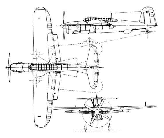
In September 1934 Fairey produced a brochure which described and illustrated the Fairey P27/32 as a universal design, being able to take on a number of different shapes each suited to a particular operational role.

Fairey Battle Article

Their first venture into the all-metal monoplane field, in which light-alloy stressed-skin construction was employed, the oval-section monocoque portion was of light-alloy hoop frames, pressed out in single pieces, each being notched to receive four special section longerons and the pre-formed skin plating. The skin plating was cut to form strips of clinker construction with the upper edge rolled to form an integral U-section stringer. After the first strip of fuselage skin had been attached to the frames, the next strip was applied with a small overlap on the previous skin, along which a closing rivet line was centred. This “stringerless” method of construction thus saved the weight of numerous long rivet lines which would have attached the separate stringers had they been employed.

The four TT-sectioned longerons, arranged as upper and lower pairs, ran three-quarters the length of the fuselage, with the inner flanges of each longeron connecting to each frame by of small brackets. A butted flat skin joint was arranged above each longeron, closure being made by a double rivet line through each skin and the outer flange on each side of the longeron.

The fuselage forward of the pilot’s bulkhead comprised the steel tube structure supporting the pilot’s cockpit flooring and the fireproof bulkhead. Light alloy subframes and sections formed the fuselage profile and sections to which fixed and detachable light-alloy panels were fitted. The power plant picked up with fittings on the firewall together with a light tubular structure which carried the detachable cowling panels.

The small centre section to the wing comprised two short lengths of spar, built up from light-alloy box sections into a girder structure, joining four heavy wing ribs. The spaces formed by the two pairs of ribs at the outboard ends each housed a large fuel tank, whilst the larger space between the inner ribs formed the bomb aimer’s compartment which was entered from the cockpit interior by means of a large aperture in the top skinning of the centre section.

Battle production in Fairey’s Stockport factory

The outer wing panels were of two-spar construction, the inner ends of girder form, changing in section to flanged beams on the outboard sections. Wing ribs containing large circular flanged lightening holes and further strengthened by deep edge flanges were pressed from light-alloy and were attached to the spars by means of angle brackets. Notched in a similar way to the fuselage frames, the wing ribs supported continuous Z section spanwise stringers, this time separate from the wing skinning. The lightalloy wing skin was applied in long flat strips, overlapped as on the fuselage skins, with single rows of rivets through the overlap and the Z stringer flange below. The underside skinning was fitted with screwed panels running spanwise, adjacent to the flying control runs and bomb release gear.

All of the movable control surfaces were of metal framing with fabric covering. The split trailing edge flaps were of metal throughout and were interconnected at their inner ends via universal joints. A simple hydraulic system was provided which powered the flaps, main undercarriage legs, and the bomb mounting crutches.
The latter permitted the bombs to be lowered clear of the wings during dive bombing. The undercarriage jack bodies were fixed attachments, whilst the ram was free to run within guides to which the leg radius rod was attached. From the fully retracted position, the first half-inch of movement of the ram unlocked the holding-up latch allowing the leg to drop down. When fully extended, self-locking was provided by the angular position of the radius rod.
The separate cockpit hoodings as on the mock-up were dispensed with on the prototype P27/32, and a single long glazed hooding was fitted which joined the two positions. Although this subsequently was found to have spoiled the pilot’s rearward view, it did much to improve the air flow and lessen wind noise around the cockpit area as discovered on wind tunnel model tests. However before the prototype machine had reached the flying stage, a contract was received for an updated airframe with the specific requirement that a third crew member must be carried so that the rear gun could be manned at all times.
This was regarded with complete horror at Hayes, and brought forth further demands from C. R. Fairey that the single-engined design be replaced with the twin-engined design. In subsequent meetings it soon became clear that a production contract was being offered provided a minimum performance could be guaranteed by the company. When Mr Fairey asked what that would be in terms of speed, the answer was not less than 195mph at 15,000 feet with full load and a crew of three. Because Mr Fairey was expecting nothing less than 270mph at that altitude with a crew of two, the guarantee was given and the production contract to Specification P23/35 was issued for no less than 155 machines. However further slippage in the delivery date of the first Merlin ‘C’ engine to Hayes, coupled with less satisfactory power output figures, did much to cause frustration in the experimental flight shed at Heathrow and greater concern at the Hayes Design Office end that the performance of the P27/32 would not reach the expected 270mph figure. In the meantime everything possible was being done to make the prototype as aerodynamically clean as possible and a further weight saving campaign was initiated.
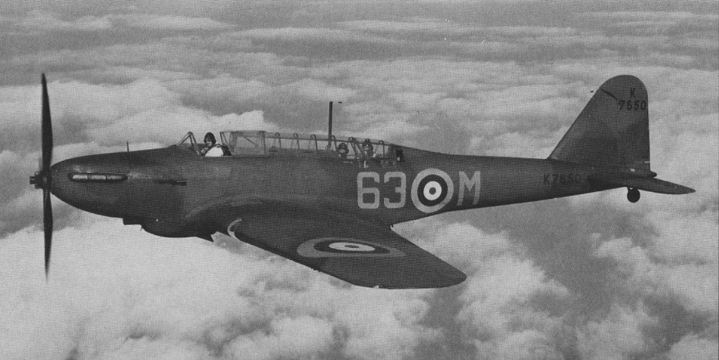
The prototype made its first flight from the Great West Aerodrome, in the hands of Flt Lt Chris Staniland, on March 10, 1936. Then fitted with a fixed-pitch three-bladed Fairey metal propeller it soon brought praise from an enthusiastic Staniland, although he was later to report that during high speed flight with the hood open the entire canopy was in danger of being ripped off. This matter was put to right when the final mock-up of the rear gun installation was approved, which enabled the final form of the hooding to be settled. The single Vickers ‘K’ gun was mounted on the familiar Fairey high-speed gun mounting, only this time with the difference that the mounting could be collapsed into a rotating cone which enabled the retracted gun to be rotated beneath the fuselage skin leaving a completely unbroken and smooth line to the rear fuselage. When finally flying in this form, and with the de Havilland two-position, three-bladed propeller, and the new letter-box exhaust manifolds as fitted to the RollsRoyce F25 engine, the Battle probably reached the peak of its perfection.
Shallow dive bombing with the pilot aiming and releasing the bomb load was thought to be the P27/32’s most suited role, and was one it was thought possible to operate with a two-man crew; but at this stage the fate of the machine was more or less sealed as an underpowered, three-seat, light, day reconnaissance/bomber.
On paper at any rate the Martlesham Heath trials showed that even under these limitations the Battle could almost make 260mph and could nearly cover 1,100 miles when flying at 200mph, and during the late summer of 1937 the Hayes Design Office concentrated on a weight saving version under the official classification of, the Battle Mk II in an effort to make the best of what had been conditioned by the Air Ministry. The first production Battle Mk I had flown from Ringway at some time during April 1937 and first arrived at the Great West Aerodrome on May 10, 1937, and subsequently went to Martlesham Heath on July 6 for its acceptance trials. Here some grim revelations were recorded, for at the new increased all-up weight the Battle Mk I K7558 could only reach 238mph at 15,000 feet.
On this basis comparative figures for the light, long-range Mk II project appeared more promising indicating a restoration of the maximum speed to 255mph at 15,000 feet, with a range in excess of 1,400 miles. But in August 1937 all such hopes of performance improvement came to a halt.

No.88 Sqn RAF

Already hundreds of Battles were beginning to take shape under the Shadow Factory Scheme and interest from Dominion and several other governments was strong. Starting in late 1935 with the company’s desire to fit a super power unit in place of the thwarted P16, designs soon evolved using first the Vulture and then the P24. When the virtual failure of the Vulture led to its replacement by the Exe and the Sabre, it was soon established that the Battle was capable of easily being converted to any suitable power unit, and the idea of a flying engine test bed was soon established. In response to demands for dual-control trainers and bombing and gunnery training conversions, detailed project drawings soon established that the changes could easily be effected at minimum cost in time, money, materials and manhours. When these facts were realised and that ex operational airframes could be retrospectively converted, the Battle appeared to have the chance of an extremely long and active life, thus in a short time hundreds more Battle orders were rushed through. Fairey production and technical resources were stretched to the limit with these undertakings in spite of having the separate Stockport factories to undertake most of the development work.
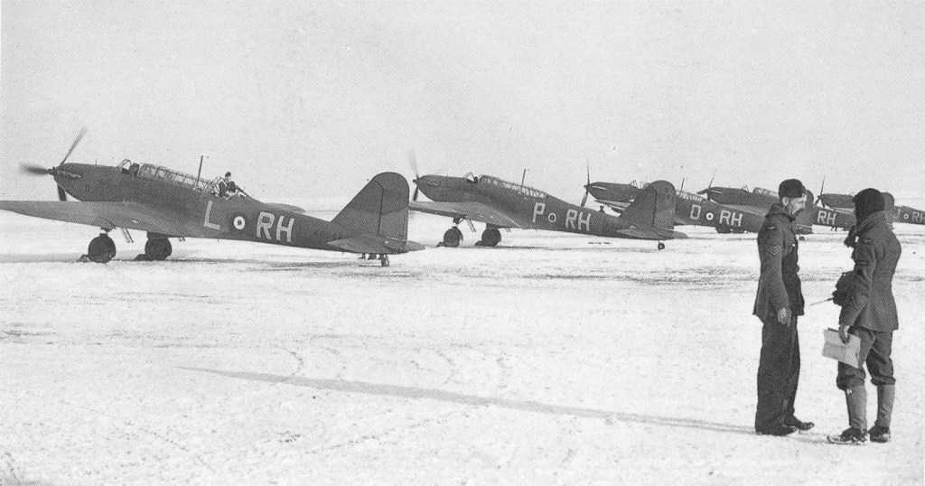
The 10 squadrons of Battle bombers of the Advanced Air Striking Force found themselves in France on September 1, 1939. With no visible signs of war taking place and prevented from aggressive action by the British Government ruling that bombing could not be directed against land targets, the Battles were employed on high altitude – photo-reconnaissance work across the German frontier, and later still to leaflet dropping sorties. These missions were undertaken in daylight without fighter protection and losses were severe, but these actions were nothing in comparison with the odds faced some six hours after the German attack had been launched on May 10, 1940, when the remains of the Battle squadrons were released to carry out their first bombing attacks on the enemy. The rear gunner of a Battle of No 88 Squadron Advanced Air Striking Force shot down a Messerschmitt Bf 109E over France on 20 September 1939: the first RAF aircraft to shoot down a German aircraft during World War II.
All told, the Air Ministry ordered some 2,419 Battles for the RAF, Dominion and foreign air forces. Of this total only 2,185 were built (1 by Hayes; 1,155 by Stockport and 1,029 by Austin). Sixteen were ordered by Belgium, which were built separately by Stockport, thus the total number of Battles constructed was 2,201.

Battle T66

The type also served with the air forces of Australia, South Africa and Turkey.

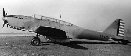
One Battle, serial K9370, was fitted with the Fairey P.24 engine and Fairey electrically operated contra-rotating constant-speed propellers – the first propellers of this type to be flight tested in the UK. First flying on 30 June 1939, to 5 December 1941 the aircraft accumulated about 86 flying hours at the hands of Flt Lieut Christopher Staniland, Mr F. H. Dixon (the company’s subsequent chief test pilot) and a number of RAF pilots.

Fairey Battle with Fairy P24 Monarch engine and coaxial propellers

It was then shipped to the USA.

Fairey Battle with Fairy P24 Monarch engine and coaxial propellers

Gallery

Prototype Battle Mk I
Engine: Rolls-Royce Merlin F, 12-cylinder 60 deg Vee, liquid cooled, 890bhp for take-off, 1,035bhp at 12,000ft.
Wing span 54ft.
Length 42ft 7in (tail up).
Height 15ft (tail up).
Root chord 11ft 4 in.
Tip chord 5ft.
Propeller dia: 11 ft 6in (or 12ft).
Wing area: 422 sq ft.
Track 9ft 8in.
Empty wt: 6,647 lb.
Loaded wt: 10,792 lb.
Wing loading: 25.6 lb/sq ft.
Power loading: 10.4 lb/hp (take-off),
Power loading: 10.9 lb/hp (supercharged).
Max speed, level: at SL: 210mph
Max speed, level: at 5,000ft: 226mph
Max speed, level: at 10,000ft: 240mph
Max speed, level: at 15,000ft: 257mph
Max speed, level: at 20,000ft: 245mph
Max speed, level: at 25,000ft: 215mph.
Cruise at 16,000ft: 200mph.
Landing speed: SL 60mph.
Climb to 5,000ft: 4 min 6 sec
Climb to to 10,000ft: 8min 24sec
Climb to to 15,000ft: 13min 36sec
Range at 16,000ft at 200mph: 1,100 mile
Range at 16,000ft at 257mph: 650 mile.

Fairey Battle Mk.I
Engine : Rolls Royce Merlin Mk.I, 1016 hp
Length: 52.067 ft / 15.87 m
Height: 15.486 ft / 4.72 m
Wingspan : 54.003 ft / 16.46 m
Max take off weight : 10793.5 lb / 4895.0 kg
Max. speed : 210 kts / 388 km/h
Service ceiling : 23491 ft / 7160 m
Range : 913 nm / 1690 km
Crew : 3
Armament : 2 MG 455 kg Bomb

Mk.III
Engine: Rolls-Royce Merlin III, 1440 hp / 755kW
Wingspan: 16.5 m / 54 ft 2 in
Length: 15.9 m / 52 ft 2 in
Height: 4.7 m / 15 ft 5 in
Wing area: 39.2 sq.m / 421.94 sq ft
Max take-off weight: 4900 kg / 10803 lb
Empty weight: 3000 kg / 6614 lb
Max speed: 257 mph @ 15,000 ft
Cruise speed: 338 km/h / 210 mph
Ceiling: 7000 m / 22950 ft
Range w/max.fuel: 1600 km / 994 miles
Armament: 2 x .303 machine-guns, 500kg of bombs
Crew: 3

Fairey G.4/31

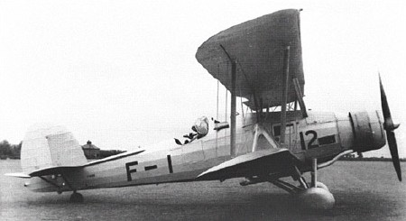
Air Ministry Specification G.4/31 called for a General Purpose aircraft, capable of level bombing, army co-operation, dive bombing, reconnaissance, casualty evacuation and torpedo bombing. The Vickers Type 253 won against the Fairey G.4/31, Westland PV-7, Handley Page HP.47, Armstrong Whitworth AW.19, Blackburn B-7, Hawker PV-4 and the Parnell G.4/31.
One prototype Fairey G.4/31 was built, first flown on 29 March 1934.

Engine; 1 x 750hp Armstrong Siddeley Tiger IV
Take-off weight; 3991 kg / 8799 lb
Empty weight; 3172 kg / 6993 lb
Wingspan; 16.15 m / 52 ft 12 in
Length; 12.45 m / 40 ft 10 in
Height; 4.78 m / 15 ft 8 in
Wing area; 61.13 sq.m / 658.00 sq ft
Max. Speed; 253 km/h / 157 mph
Ceiling; 7071 m / 23200 ft
Crew; 2-3
Armament; 2 x 7.7mm machine-guns, 1 x 450kg or 3 x 227kg bombs or 1 torpedo

Fairey P.4/34

Two prototypes, first flown on 13 June 1937. No production.

Engine; 1 x 1030hp Rolls-Royce Merlin I (later II)
Take-off weight; 3989 kg / 8794 lb
Empty weight; 2908 kg / 6411 lb
Wingspan; 14.43 m / 47 ft 4 in
Length; 12.19 m / 39 ft 12 in
Height; 4.29 m / 14 ft 1 in
Max. Speed; 456 km/h / 283 mph
Ceiling; 8108 m / 26600 ft
Range; 1481 km / 920 miles
Crew; 2

Fairey TSR.II / Fairey Swordfish

Swordfish II

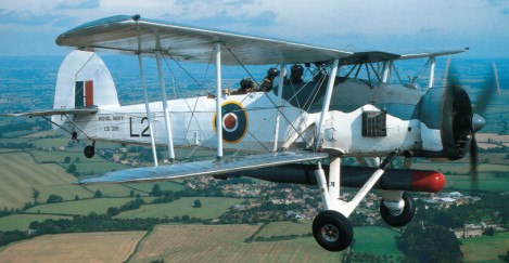
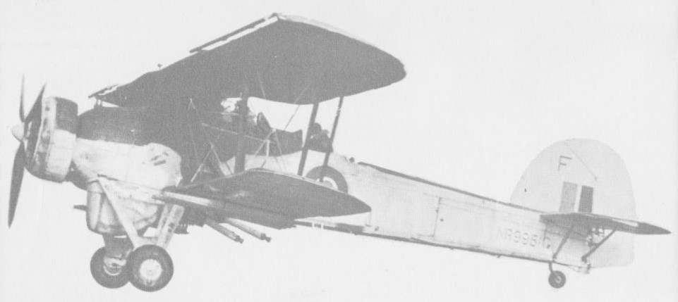
In 1933 the Fairey Aviation Company privately financed and built the TSR.1, a biplane torpedo spotter reconnaissance aircraft, from which the Swordfish evolved. Although the first TSR.I crashed, it had undergone sufficient tests to prove the feasibility of the design, and Fairey built the TSR.II, a slightly larger aircraft. It was designed by Marcelle Lobelle to meet the Naval Spec S.15/33.

Fairey TSR.II / Fairey Swordfish Article

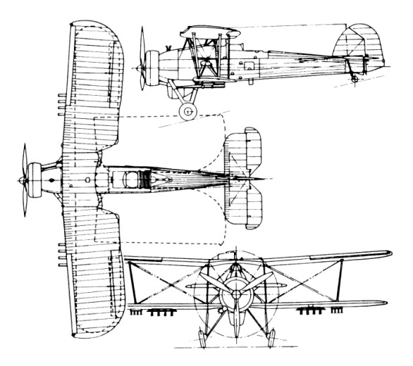
First flying from Harmondsworth on 17 April 1934, and after numerous modifications a specification (S.38/34) was written around the aircraft. Official testing proved it to be a stable and reliable aircraft. The fuselage, 36ft 4in long, was rectangular in section and featured a bolted steel tube frame. The aft portion was fabric covered, but detachable metal panels, for easy access, were fitted from the cockpit forward. The crew consisted of a pilot, navigator and bomb-aimer.
The equal span biplane wings were of fabric covered metal construction, and the upper wing centre section was attached to the fuselage by a pyramid structure and carried the hoisting sling. The lower wings were braced to the fuselage by an inverted V strut. The wing cellules could be manually folded for compact storage. The leading edge of the upper wing was fitted with Handley Page slots, and ailerons were fitted to both upper and lower wings.
The undercarriage used medium pressure tyres and pneumatic brakes. Each of the main units consisted of an oleo shock absorber leg connected to the lower centre section front spar, and two inner struts hinged to the fuselage. The design was strengthened to withstand catapult launches and arrester hook landings. Early production Swordfish, built to Air Ministry Specification S.33/34, were powered by an air cooled 690 hp Bristol Pegasus IIIM3 radial engine. Blessed with superb handling characteristics, the Swordfish performed extremely well on carrier borne operations, being able to operate from pitching decks in stormy conditions. It had a range of 546 miles and a maximum speed of 138 mph at 5,000ft.

The propeller was a three-blade Fairey-Reed metal.

The Swordfish carried 155 Imp.Gal / 705 lt of fuel in its min tank and 12.5 Imp.Gal / 57 lt in a gravity tank, both behind the Pegasus IIIM3 or Mk.30 engine.

The first batch of production Fairey Swordfish rolled off the assembly line during December 1935, and were operating with the Royal Navy’s Fleet Air Arm (FAA) within two months. By 1939, on the eve of the Second World War, there were 13 operational squadrons of the type. A total of 689 aircraft had been delivered or were on order.
The Swordfish Mk I’s defensive armament comprised a fixed forward firing synchronised Vickers machine gun and a movable Vickers K gun on a Fairey high speed mounting in the rear cockpit. The offensive load could be a single 18in 1,610 lb torpedo, or one 1,500 lb mine, or 1,500 lb of bombs. The Mk II, which appeared in 1943, had a strengthened lower wing capable of carrying eight 601b rocket projectiles.
The final production version, the Mk III, had an ASV Mk X radar scanner in a radome under the fuselage. In Canada, canopy equipped Mk.IIs and IIIs were designated Mk IVs. The No 1 Naval Air Gunners School at Yarmouth, Nova Scotia, operated 105 Swordfish. Considered obsolete at the beginning of the war, the Swordfish outlived its successors and survived the war with an impressive battle record; the type is credited with sinking a greater tonnage of Axis shipping than any other torpedo bomber.

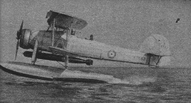
The Swordfish first made big news in the seaplane form, when a Swordfish catapulted from HMS Warspite not only spotted for the British naval force during the battle in Ofot Fiord, Norway, on April 13, 1940, but itself bombed and sank a submarine and fin¬ished off an enemy destroyer that had been dam¬aged by the ships.
Seven months later, Swordfish from the carrier Illustrious achieved one of the most spectacular successes in naval air warfare. In two waves or twelve and nine aircraft, they dived into Taranto Harbour under cover of darkness and launched their bombs and torpedoes to such effect that three Italian battleships, a cruiser and two destroyers were seriously damaged, two naval auxiliaries sunk and shore installations heavily damaged all for a loss of two Swordfish. Another major success was achieved on May 26, 1941, when Swordfish of 818 Squadron so crippled the battleship Bismarck that the Navy was able to intercept and sink it. The well remembered attack on the Scharnhorst and Gneisenau in the Channel cost the lives of 13 of the 18 men who took part.
Outliving its intended replacements, the Fairey Albacore and Barracuda, the Swordfish served until the war’s end. Production ended on 18 August 1944, by which time a total of 2,396 Swordfish were built.

Gallery

Engine: Bristol Pegasus, 690 hp
Wingspan: 45 ft 6 in
Length: 36 ft 4 in
Takeoff weight: 9250 lb
Max speed: 139 mph
Seats: 2-3

Swordfish Mk II
Engine: 1 x Bristol Pegasus XXX, 559kW / 740 hp
Max take-off weight: 3406 kg / 7509 lb
Empty weight: 2132 kg / 4700 lb
Wing loading: 12.3 lb/sq.ft / 60.0 kg/sq.m
Wingspan: 13.87 m / 45 ft 6 in
Length: 10.87 m / 35 ft 8 in
Height: 3.76 m / 12 ft 4 in
Wing area: 56.39 sq.m / 606.98 sq ft
Max. speed: 120 kt / 222 km/h / 138 mph
Cruise speed: 104 kt / 193 km/h / 120 mph
Service ceiling: 3260 m / 10700 ft
Range: 1658 km / 1030 miles
Armament: 2 x 7.7mm machine-guns, 1 x 730kg torpedo or 680kg of bombs
Crew: 2-3

Fairey Swordfish