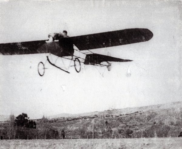
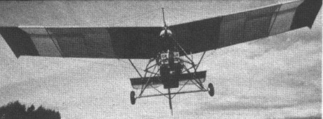
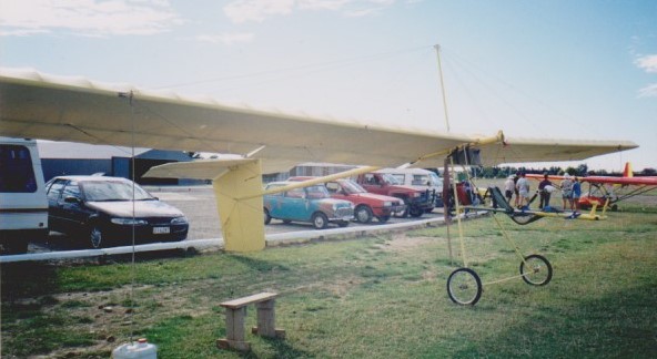
Percy Fisher began the design of his aircraft in June 1911, and the machine was finally finished in November 1912. On Christmas day 1912, Fisher attempted his first flight at Pigeon Bush in the Wairarapa. It was a short hop into the air, followed by a heavy crash. While the engine was powerful enough to lift the aircraft into the air, the basic configuration presented some severe control problems. On 28 April 1913 with Reginald White at the controls, the Fisher monoplane made its first successful short flights at Pigeon Bush. After the Gladstone flights in June 1913, several different pilots occasionally flew the aircraft, before it was retired in early 1916. The only remains of the aircraft in 2003 were the two cylinders at Southward’s Museum. Percy Fisher went on to have a very successful engineering business in Wellington, New Zealand. He died in 1941.
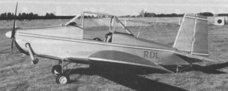
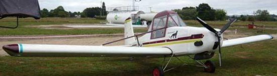
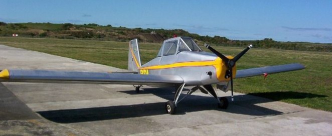
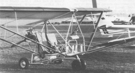
Designed by Bobby Baker and first shown in public in 1984. Built up from wood from plans supplied by the First Strike, the fuselage is constructed out of spruce longerons and plywood bulkheads, resulting in a strong, light and inexpensive approach for the homebuilder. Powered by a Rotax engine. Finished in ceconite and dope. Centre mounted joy stick, rudder pedals, tailwheel steerable through rudder pedals. The wings are removable for trailering, set up time being cited as 20 minutes. Designer Bobby Baker notes that some owners have been using the Bobcat for spray work, however he cautions that the design requires some beefing up – seen as no problem – before the additional load is carried. Suggestions for beefing up the structure, putting the craft up out of the microlight category, are included with the initial plans.
Supercat
The Supercat is a strengthened version with a slightly shorter wingspan and greater performance capabilities.
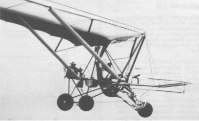
Bowdler Aviation Inc markets plans and kits to build the Supercat single-seat monoplane, formerly developed by First Strike and first flown 1984. The SuperCat has removable wings, taking less than one hour with two people, and fold up tail feathers.
In 1943 Firestone absorbed G and A Aircraft of Pitcairn Field, Willow Grove, and this included the CG-4A, a troop-carrying glider, and the XO-61, a pusher-type autogyro. Between 1943 and 1945 the G and A was modified and developed into a dual tandem helicopter, the XR-9B.
G&A Aircraft had previously built six examples of the XO-61 two-seat gyroplane for the U.S. Army. This experience was applied to the design of a new helicopter for the U.S. Army, designated Model 45.
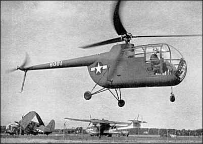
Conceived in 1943, the Model 45 was a conventional pod and boom helicopter with tandem seating, a fixed tricycle undercarriage and a three-blade main rotor. Completed in 1944 with co-operation from the Army Air Force’s Air Technical Service Command, the main rotor had three blades (and a fixed-type head); the tail rotor was 1.98 metres in diameter.
The helicopter was made of welded steel tube covered with an alloy skin, while the tail boom had a balsa-wood core covered with alcad. For storage purposes this helicopter could be broken down into three parts: rotor blades, fuselage and boom assembly. The prototype incorporated an experimental electro-hydraulic governor, which by acting on the simultaneous pitch control maintained a constant predetermined rotor speed, irrespective of the power used. With automatic assistance from this governor, the pilot could rise or descend vertically just by using his throttle.
The original Model 45B design used a 126hp XO-290-5 engine and the Model 45C (military XR-9A) was a development with a two-blade rotor. Neither of these were actually built and the prototype (which carried the identity 6001) was designated XR-9B and was fitted with a 135hp Lycoming O-290-5 engine. Firestone also built a civil version, the Model 45D (NX58457), with side-by-side seating but development of helicopters was abandoned by Firestone in 1947.
XR-9B Number of seats: 2 Engine: 1 x Lycoming O-290-7, 135hp Rotor diameter: 8.53m Length: 8.41m Width at landing wheels: 2.74m Height: 2.6m Gross weight: 800kg Cruising speed: 128km/h Inclined climb: 305m/min Absolute ceiling: 3050m Range: 400km
Side by side two seat single engined high¬wing monoplane with conventional three axis control. Wing has swept back leading and trailing edges, and constant chord; no tail, canard wing. Pitch control by fully flying canard; yaw control by tip rudders; roll control by spoilers; control inputs through stick for pitch/roll and pedals for yaw. Wing braced from below by struts; wing profile; double surface. Undercarriage has four wheels in ‘tricycle’ formation; suspension on all wheels. No ground steering. Brakes on all wheels. Aluminium tube framework, without pod. Engine mounted below wing driving pusher propeller. Easily distinguishable from other Fledge derivatives by its unusual double nosewheel, the T1 is basically a two seat version of the M1. It was first shown at the Aero 83 Exhibition at Friedrichshafen in March 1983 and was placarded as having made its first flights the month before. The standard version includes electric start, while options include wheel fairings and floats.
Engine: Hirth 276A13, 40 hp at 7000 rpm. Propeller diameter 63 inch, 1.60 m. Belt reduction, ratio 2.04. Max static thrust 252 lb, 114 kg. Power per unit area 0.22 hp/sq.ft, 2.4 hp/sq.m. Length overall 10.5ft, 3.20m. Wing span 32.8 ft, 10.0 m. Constant chord 5.6 ft, 1.70 m. Canard span 6.7 ft, 2. 00 m. Main wing area 183 sq.ft, 17.0 sq.m. Rudder area 9.7 sq.ft, 0.90 sq.m. Wing aspect ratio 5.9/1. Wheel track 5.3 ft, 1.60 m. Empty weight 327 lb, 148kg. Max take off weight 707 lb, 320kg. Payload 380 lb, 172 kg Max wing loading 3.86 lb/sq.ft, 18.8 kg/sq.m. Fuel capacity 6.9 US gal, 5.7 Imp gal, 26.0 litre. Max power loading 17.7 lb/hp, 8.0kg/hp. Load factors: +6.0, 3.0 ultimate. Never exceed speed 56mph, 90kph. Economic cruising speed 44mph, 70kph. Stalling speed 28mph, 45 kph. Max climb rate at sea level 600 ft/min, 3.1 m/s. Best glide ratio with power off 8/1 at 37mph, 60kph. Take off distance 100ft, 30 m. Landing distance 65 ft, 20 m. Range at average cruising speed 112 mile, 180km.
The prototype of the single seater M1 from Firebird made its first flight in 1979 and by 1983 more than 100 examples have been produced. The wing is directly descended from the famous Fledgling designed by Klaus Hill, originally as a hybrid control hang-¬glider. This wing, with its rudders at its wing tips, was powered in 1978 in the USA and the following year in Europe, by Firebird. Just as Pterodactyl does with its Ptraveler and Ascen¬der, Firebird uses it with a variable incidence canard. There is one fundamental difference between Firebird’s approach and that of the Americans, in that the German manufacturer chooses to support the wing with two profiled struts under each half wing, thus dispensing with all the ground and flight rigging wires. The other principal difference is the power pack, which on the Firebird has to conform with West Germany’s stringent noise regulations. With Konig en¬gine and three bladed propeller, the standard arrangement on the M1, under 60 dB is recorded using the regulation measuring conditions. Complete with electric start and battery, the M1 cost DM 17,408 in 1983, while options in¬clude an extra fuel tank, an instrument panel, floats and a parachute of 755 sq.ft (70 sq.m) area, which is usable at speeds up to 155 mph (250 kph) and which gives a rate of descent of 1300 ft/min (6.7 m/s) with a 442 lb (200 kg) load. Wing profile; FNI 4 81; double surface. Undercarriage has three wheels in tricycle formation; steel spring suspension on nosewheel and no suspension on main wheels. Push right go left nosewheel steering independent from yaw control. Brake on nosewheel. Aluminium tube/carbon fibre framework, without pod. Engine mounted below wing driving pusher propeller.
Engine: Konig SC430, 24 hp at 4200 rpm. Propeller diameter 53 inch, 1.34 m (three blade). Belt reduction, ratio 2.2/1. Max static thrust 143 lb, 65 kg. Power per unit area 0.15hp/sq.ft, 1.6 hp/sq.m. Height overall 9.4 ft, 2.85 m. Wing span 32.8 ft, 10.00 m. Chord at root 5.6 ft, 1.70 m. Chord at tip 4.6ft, 1.40m. Dihedral 5 degs. Sweepback 38 degs. Canard span 6.6ft, 2.00m. Canard chord 2.1 ft, 0.63 m. Total wing area 175 sq.ft, 16.3sq.m. Main wing area 161 sq.ft, 15.0 sq.m. Canard area 14.0 sq.ft, 1.3 sq.m. Wing aspect ratio 6.7/1. Wheel track 6.9 ft, 2. 10 m. Wheelbase 4.6 ft, 1.40 m. Nosewheel diameter overall 14 inch, 35 cm. Main wheels diameter overall 16 inch, 41 cm. Empty weight 2161b, 98kg. Max take off weight 420 lb, 190 kg. Payload 204 lb, 92 kg. Main fuel capacity 3.4 US gal, 2.8 Imp gal, 13.0 litre Reserve fuel capacity 2.6 US gal, 2.2 Imp gal, 10.0 litre in. Max wing loading 2.60 lb/sq.ft, 12.7 kg/sq.m. Max power loading 17.5 lb/hp, 7.9 kg/hp. Load factors +4.0, 2.0 design; +6.0, 3.0 ulti¬mate. Max level speed 50 mph, 80 kph. Never exceed speed 56 mph, 90kph. Economic cruising speed 37mph, 60kph. Stalling speed 24mph, 40kph. Max climb rate at sea level 400 ft/min, 2.0 m/s. Min sink rate 350ft/min at 34mph, 1.8m/s at 55 kph. Best glide ratio with power off 8.5/1 at 37mph, 60kph. Take off distance 100ft, 30 m. Landing distance 65 ft, 20 m. Range at average cruising speed 93 mile, 150 km.
Otherwise known as the “Mangamingi Monster Mark III” this aircraft was designed by Tim Hardwick-Smith to achieve a low horsepower, slow flying aeroplane, for low cost flying, farm surveillance and motor gliding. The machine first flew on 1 February 1997 and was registered ZK-JHH on 13 February 1997.
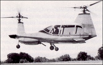
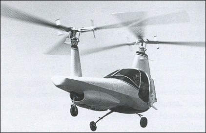
The Beta 200 prototype (N5000F) was first flown on 26 May 1966. Filper planned several versions of the Beta with either two seats (Model 200A and 300) or four seats (Model 400A and 600A). The four-seat models had a fuselage which was stretched by 36-inches and the first Beta 400A (N5003F) was flown on 13 July 1967. The Beta 400A had a 250hp Continental IO-520. Details of the Model 600A are unknown. A former N.A. test pilot and a flight test engineer were killed in the stretched version. Registration records show that 32 Betas were completed, comprising two Model 100As, 29 Model 400As and one Model 600A, but there is some doubt as to whether all of these were completed. It is believed the company ceased operations in 1969.
Under the direction of William Orr, Filper Research designed a novel helicopter using the ‘Gyroflex Rotor’, which employed special balance weights fitted to the roots of the rotor blades instead of conventional flapping or lead-lag hinges, or other hub stability devices. Filper was in the peach-pitting machinery business. This concept was tested on the Filper Helicopter (N9712C) which had fore and aft rotor pylons and the pilot sitting astride a central beam which also carried the engine. A commercial development was the Filper Beta 100A. This was a tandem rotor machine with a two-seat cabin and pylon at the rear, and the engine with the forward pylon in front. This arrangement resulted in the pilot being unusually far from the front of the helicopter. The Beta 200 prototype (N5000F) was first flown on 26 May 1966. Filper planned several versions of the Beta with either two seats (Model 200A and 300) or four seats (Model 400A and 600A). The Beta models had various powerplants – namely the 210hp Continental IO-360-E (Model 200A), Allison 250-C18 turbine (Model 300) and 250hp Continental IO-520 (400A). Details of the Model 600A are unknown. Registration records show that 32 Betas were completed, comprising two Model 100As, 29 Model 400As and one Model 600A, but there is some doubt as to whether all of these were completed. No Filpers were ever sold to the public and never received FAA certification. It is believed the company ceased operations in 1969.