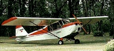
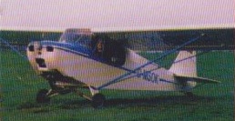
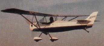
The Super Koala 2 seat development of the Koala adds another seat for side-by-side. The cockpit has dual controls and the wings detach for storage. Options are a 52 or 64 horsepower Rotax engine for cruise speeds of 65-85 mph, allowing hands-off flying. First flown in 1983, by 2004 100 had been sold.
Super Koala Engine; Rotax 503, 52 hp Wingspan; 31′ Wing Area; 140 sq. ft. Height; 5’7″ Length; 18’1″ Fuel Capacity; 8 USgal. Fuel Consumption @ 75%; 3 USgal/hr. Design Loads; +4.6 -2.3g Drive Type; Geared Gross Weight; 740 lbs. Empty Weight; 350-375 lbs. Construction Time; 500 hrs. Field Assembly Time; 20 min. Velocity-Never Exceed; 95 mph Cruise Speed Solo; 75-80 mph Stall Speed (w/flaps) Solo; 28 mph Climb Rate Solo; 1000 fpm Glide Ratio Solo; 9:1 Takeoff Run Solo; 150′ Landing Roll Solo; 200′ Cruise Speed Gross; 70-75 mph Stall Speed (w/flaps) Gross; 30 mph Climb Rate Gross; 700 fpm Glide Ratio Gross; 9:1 Takeoff Run Gross; 200′ Landing Roll Gross; 250′
Super Koala Engine; Rotax 582LC, 64 hp Wingspan; 31′ Wing Area; 140 sq. ft. Height; 5’7″ Length; 18’1″ Fuel Capacity; 8 USgal. Fuel Consumption @ 75%; 4 USgal/hr. Design Loads; +4 -2.2g Drive Type; Geared Gross Weight; 830 lbs. Empty Weight; 375-400 lbs. Construction Time; 500 hrs. Field Assembly Time; 20 min. Velocity-Never Exceed; 95 mph Cruise Speed Solo; 75-80 mph Stall Speed (w/flaps) Solo; 29 mph Climb Rate Solo; 1400 fpm Glide Ratio Solo; 9:1 Takeoff Run Solo; 125′ Landing Roll Solo; 200′ Cruise Speed Gross; 70-75 mph Stall Speed (w/flaps) Gross; 32 mph Climb Rate Gross; 1100 fpm Glide Ratio Gross; 9:1 Takeoff Run Gross; 150′ Landing Roll Gross; 250′
Super Koala Stall: 45 kt / 52 mph / 83 kmh Cruise: 60 kt / 69 mph / 111 kmh VNE: 95 kt / 109 mph / 176 kmh Empty Weight: 201 kg / 443 lbs MTOW Weight: 376 kg / 829 lbs Climb Ratio: 1000 ft/min / 5 m/s Glide Ratio: 9:1 Take-off distance (50ft obstacle): 430 ft / 130 m Landing distance (50ft obstacle): 560 ft / 172 m 2009 Price: US$14,300
First flown in 1982, 200 were sold by 2004. A low wing, single seat ultralight designed to be as portable as possible, the 303’s wings are easily folded back to rest on the cantilevered horizontal stabilizer. Field assembly time is less than 10 minutes. Take-off roll is 100 feet, with a climb rate of 800 feet per minute. In the 303, visibility is always good. The cockpit is situated slightly forward of the wing’s leading edge, giving a clear view of what’s above, around and below. The FP-303 has a centre mounted joy stick, rudder pedals, and tailwheel steerable through rudder pedals. In 1997 the plans cost US$195.
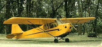
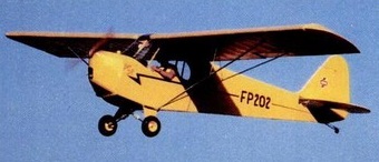
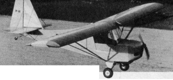
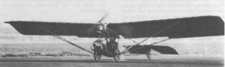
First flown in 1981, for those who like to work with wood, Fisher Flying Products of Ohio market the FP202 Koala kitset Cub replica, a design which utilises the geodetic construction method. Centre mounted joy stick, rudder pedals, tailwheel steerable through rudder pedals. Detachable wings. An aluminum strut braced main spar carrythrough, a ground adjustable horizontal stabilizer, 14-inch pneumatic tires with rubber shock cord, and removable cockpit panels for summer flight.
In 1984 the Fisher Koala kit was priced at $4750 with a 40 hp engine.
By 2004, 325 had been sold.
FP-202 Engine; 2 Cycle, 1 Cyl, 28 HP Prop Diameter/Pitch; 60″/28″ Reduction Ratio; 2.58-to-1 Wingspan; 29’10” Length; 17’9″ Height; 5’5″ Wing Area; 120 sq. ft. Fuel Capacity; 5 gal./2 gph Gross Weight; 500 lbs. Empty Weight; 250 lbs. Useful Load; 250 lbs. Wing Loading; 4.17 psf Power Loading; 13 lb/hp Design Load Factors; +4 -2.5g Construction Time; 500 hrs. Field Assembly Time; 15 min. Velocity-Never Exceed; 75 mph Top Level Speed; 60 mph Cruise Speed; 55mph @ 65% power Stall Speed; 26 mph Sea Level Climb Rate; 900 fpm @ 40 mph Takeoff Run; 95′ Landing Roll; 125′ Range at Cruise; 135 mi L/D (Glide Ratio); 9-to-1 @ 40 mph
FP-202 Koala Engine: Rotax 277, 28 hp. Static thrust: 200 lbs. Speed max: 62 mph. Cruise: 57 mph. Height: 5.8 ft. Length: 17.9 ft. Wing span: 29.9 ft. Wing area: 120 sq.ft. Wing loading: 4.16 lbs/sq.ft Power loading: 17.85 lbs/hp Fuel cap: 5 USG. Weight empty: 245 lbs. Gross: 500 lbs. Vne: 75 mph Range: 180 sm. Stall: 26 mph. ROC: 750 fpm. Take-off dist: 150 ft. Landing dist: 150 ft. Design limits: +4, -2.5g. Glide ratio: 9-1. Service ceiling: 13,000 ft. Seats: 1. Landing gear: tail wheel.
Engine: Rotax 277, 25 hp Wing span: 9.10 m Wing area: 10.5 sq.m MAUW: 226 kg Empty weight: 110 kg Fuel capacity: 19 lt Max speed: 97 kph Cruise speed: 75 kph Minimum speed: 40 kph Climb rate: 3.5 m/s Certification: Vz Seats: 1 Fuel consumption: 7 lt/hr Plan price (1998): US$250 Kit price (1998): US$5922
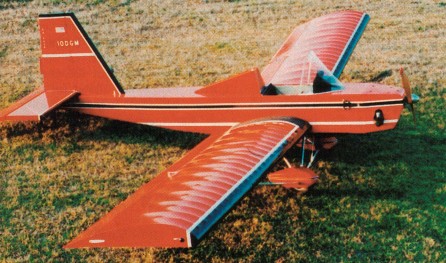
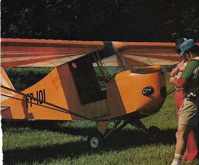
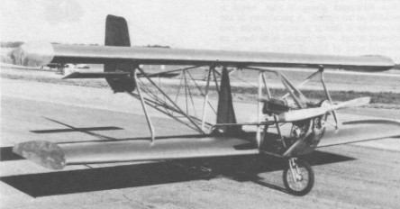
Single seat single engined high wing mono¬plane with conventional three axis control. Wing has unswept leading and trailing edges, and constant chord; conventional tail. Pitch control by elevator on tail; yaw control by fin mounted rudder; roll control by half span ailerons; control inputs through stick for pitch/roll and pedals for yaw. Wing braced from below by struts; wing profile; double surface. Undercarriage has three wheels in tail dragger formation; steel spring suspension on tailwheel and bungee suspen¬sion on main wheels. Push right go right nosewheel steering connected to yaw control. Wood/fabric fuselage; enclosure. Engine mounted below wing driving tractor propeller. All wood geodetic construction with aluminium tube struts and landing gear, steel tubing engine mount and glass fibre cowling. Covered with aircraft heat shrink cloth. Shown publicly for the first time at Oshkosh in 1982, the FP 101 is radically different from the other Mike Fisher products. Mike Fisher offered four permutations of the FP 101: two engines (Zenoah G25B with 22 hp or Kawasaki TA440A with 40 hp) and two wing spans (35ft, 10.67m or 29ft, 8.84 m).
Unlike the Barnstormer and the Boomer¬ang from the same company, this machine is not available as plans, but only as a kit, which can be purchased in three ways. First, the FP 101 can come as four part kits: wings, fuselage and hardware at $750 each and either a Zenoah power pack for $1398 or a Kawasaki power pack for $1850. Alternatively the airframe kits can be together for $2150 (short span) or $2350 (long span), with power packs as before. Finally the kit can be purchased complete with Zenoah for $3350 (short span) or $3550 (long span), equivalent figures for the Kawasaki variant being $3798 and $3998 in 1982.
Engine: Zenoah G25B, 22 hp at 6500 rpm. Propeller diameter and pitch 50 x 24 inch, 1.27 x 0.60 m. V belt reduction, ratio 2.0/1. Power unit area 0.16 hp/sq.ft, 1.7 hp/sq.m. Fuel capacity 5.0 US gal, 4.2 Imp gal, 18.9 litre. Length overall 16.5ft, 5.03m. Wing span 34.8 ft, 10.62 m. Chord at root 4.0 ft, 1.22 m. Sweepback 0 degs. Total wing area 140 sq.ft, 13.0 sq.m. Wing aspect ratio 8.7/1. Main wheels diameter overall 14 inch, 35 cm. Empty weight 210 lb, 95 kg. Max take off weight 500 lb, 227kg. Payload 290 lb, 132kg. Max wing loading 3.57 lb/sq.ft, 17.4 kg/sq.m. Max power loading 22.7 lb/hp, 10.3 kg/hp. Max level speed 55 mph, 88 kph. Never exceed speed 70 mph, 113 kph. Max cruising speed 55 mph, 88 kph. Economic cruising speed 40 mph, 64 kph. Stalling speed 15 mph, 24 kph. Max climb rate at sea level 450 ft/min, 2.3 m/s. Take off distance 100 ft, 30 m. Landing dis¬tance 150 ft, 45m.
Engine: Kawa¬saki TA440A, 40 hp at 6000 rpm. Propeller diameter and pitch 54 x 27 inch, 1.37 x 0.69 m. V belt reduction, ratio 2.4/1. Max static thrust 230 lb, (104) kg. Power unit area 0.29 hp/sq.ft, 3.1 hp/sq.m. Fuel capacity 5.0 US gal, 4.2 Imp gal, 18.9 litre. Length overall 16.5ft, 5.03m. Wing span 34.8 ft, 10.62 m. Chord at root 4.0 ft, 1.22 m. Sweepback 0 deg. Total wing area 140 sq.ft, 13.0 sq.m. Wing aspect ratio 8.7/1. Main wheels diameter overall 14 inch, 35 cm. Empty weight 250 lb, 113 kg. Max take off weight 500 lb, 227kg. Payload 250 lb, 113kg. Max wing loading 3.57 lb/sq.ft, 17.4 kg/sq.m. Max power loading 12.5 lb/ hp, 5.7 kg/hp. Max level speed 55 mph, 88 kph. Never exceed speed 70 mph, 113 kph. Max cruising speed 55 mph, 88 kph. Economic cruising speed 45 mph, 72 kph. Stalling speed 22 mph, 35 kph. Max climb rate at sea level 850 ft/min, 4.3 m/s. Best glide ratio with power off 10/1. Take off distance 75 ft, 23 m. Range at aver¬age cruising speed 125 mile, 200 km.
Wingspan; 29ft, 8.84 m Length 13 ft 10 in Empty weight 250 lbs. Gross weight 500 lbs Cruise speed 55 mph. Stall speeds 24 mph. Takeoff/landing roll 100ft. Climb rate 850 fpm. Fuel capacity 5 USG.
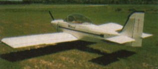
Single seat single engined high wing mono¬plane with conventional three axis control, first flown in 1982. Wing has unswept leading and trailing edges, and constant chord; cruciform tail. Pitch control by elevator on tail; yaw control by fin mounted rudder. Control inputs through stick for pitch/roll and pedals for yaw. Wing braced from below by struts; wing profile; double surface. Undercarriage has tall dragger formation and rigid suspension with 20-inch main wheels. Aluminium tube framework, without pod. Engine mounted below wing driving tractor propeller. Frame: 6061T6 and 2024T3 aluminium. Wing: 2.7 oz Stits Polyfiber. Like the Barnstormer, the Boomerang monoplane is also intended for home builders, to whom Fisher Flying sell through intermediary Wicks Aircraft in plan form for $65 or as a complete kit for $3720. The standard aircraft is fitted with a twin cylinder 340 cc Kawasaki engine of 30 hp with 2.0 reduction which is less frequently used than the TA440 436 cc Kawasaki giving 38.5 hp, which is available as an option. A peculiarity of the Boomerang is that it is available with two different wings an option is to have an enlarged wing of 32ft (9.75m) span. Wing area is increased in proportion, which allows the aircraft to be used as a two seater, though it is then included in the experimental aircraft category and no longer qualifies as an ultralight in the USA. Like Mike Fisher’s biplane, the Boomerang was also sold in the form of sub assembly kits: wing for $1175; fuselage for $585; covering for $425 and motor for $1450, in 1982.
Engine: Kawasaki 340 cc, 30 hp. Propeller diameter and pitch 54 x 22 inch, 1.37 x 0.56 m. Reduction ratio 2.0/1. Power per unit area 0.19 hp/sq.ft, 2.1 hp/sq.m. Fuel capacity 2.5 US gal, 2.1 Imp gal, 9.5 litre Optional fuel capacity 5.0 US gal, 4.2 Imp gal, 18.9 litre. Wing span 28.0 ft, 8.53 m. Mean chord 5.6 ft, 1.70 m. Total wing area 156 sq.ft, 14.5 sq.m. Wing aspect ratio 5.0/1. Main wheels diameter overall 20 inch, 50 cm. Empty weight 190 lb, 86 kg.
Single seat single engined negative stagger biplane with conventional three axis control. Wings have unswept leading and trailing edges, symmetrical double-surface, and constant chord; conventional cruciform tail. Pitch control by elevator on tail; yaw control by fin mounted rudder; roll control by full -span ailerons; control inputs through stick for pitch/roll and pedals for yaw. Wings braced by struts; wing profile NACA 23015; double surface. Undercarriage has three wheels in tricycle formation; bungee suspension on all wheels. Flush right go right nosewheel steering connected to yaw control. Brakes on 16-inch main wheels. Aluminium tube framework, without pod. Twin cylinder Kawasaki 440A with 2.0 reduction and recoil restart capability engine mounted below wing driving tractor propeller. Frame: 6061T6 and 2024T3 aluminium. Wing 2.7oz Stits Polyfiber. The prototype of this biplane was shown for the first time at Oshkosh in August 1982. Essentially in-tended for home builders, the Barnstormer has been available from Fisher Flying Pro¬ducts since the end of 1982 as plans for $95 or as a complete kit with Kawasaki TA440 engine for $4355. In order to give greater flexibility to the builder, various sub assem¬bly kits are also available as follows: tail surfaces kit $285; wings kit $1175; fuselage kit for $1050; covering $395; power unit $1650. Options include a ground adjustable two-¬bladed variable pitch propeller and shor¬tened wings down from 20 ft (6.09 m) span to 17.5 ft (5.33 m).
Engine: Kawasaki TA 440A, 38.5 hp at 6000 rpm. Propeller diameter 58 inch, 1.47m. Reduction ratio 2.0/1. Power per unit area 0.21hp/sq.ft, 2.4hp/sq.m. Fuel capacity 1.7 US gal, 1.4 Imp gal, 6.6 litre Optional fuel capacity 5.0 US gal, 4.2 Imp gal, 18.9 litre. Wing span 20.0ft, 6.09m. Constant chord 4.0 ft, 1.21 m. Sweepback 0 degs. Total wing area 176 sq.ft, 16.4 sq.m. Aspect ratio of each wing 4.5/1. Nosewheel diameter overall 16 inch, 40 cm. Main wheels diameter overall 16 inch, 40 cm. Empty weight 220 lb, 100 kg. Wing loading, 2.19 lbs/sq.ft.
In February of 1942, the USAAF issued a Request For Proposals for a fighter/interceptor of high performance. Maximum speed was to be 440 mph at 2000 feet, operational ceiling was to be 38,000 feet, and range was to be 2500 miles. A special requirement was added for the initial climb rate, which was to be no less than 5600 feet per minute.
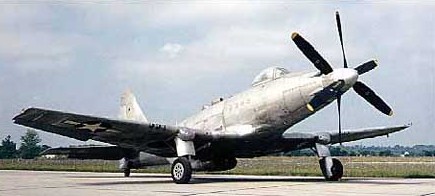
P-75A Eagle
In April of 1942, Donovan Berlin (who had been responsible for the P-36 and the P-40) left the Curtiss company to take over the directorship of the Aircraft Development Division of the Fisher Body Division of the General Motors Corporation. One of his first assignments was in response to the USAAF request. In September of 1942, Fisher submitted their proposal using the most powerful liquid-cooled engine then available, the 2,885-hp twenty-four cylinder Allison V-3420. This engine was basically a pair of coupled V-1710 engines, mounted side-by-side in a W-type configuration. Significant savings in cost and time were to be gained by employing major assemblies from existing aircraft already in production in the manufacture of the new interceptor.
The first of two proto¬type XP-75s that flew on 17 November 1943 was built with P-51 Mustang outer panels, F4U Corsair landing gear and A-24 Dauntless empennage.
On October 10, 1942, a contract for two prototypes was awarded to Fisher under the designation XP-75.
Serial numbers 43-46950 and 43-46951 were assigned to the two XP-75 prototypes. The Allison engine was to be located behind the cockpit and was to drive a set of contra-rotating propellers via an extension shaft and a reduction gearbox. The engine was cooled by a duct in the ventral fuselage. Initially, it was planned that the outer wing panels of the P-51 Mustang would be used in an inverted-gull configuration. However, at an early stage it was decided to drop the inverted gull-wing configuration and go with a straight wing design utilizing outer wing panels from a P-40.
By the summer of 1943, the USAAF had a more urgent need for long-range escort fighters than it did for fast-climbing interceptors. The urgent demand to exploit existing components was abruptly dropped. On July 6, 1943, the USAAF ordered six more prototypes that would be adapted to fulfill the long-range escort role. They were assigned the designation XP-75A, and the serial numbers were 44-32161/32166. They were to be powered by an Allison V-3420-23 engine, and were to be armed with six 0.50-inch machine guns in the wings and four 0.50-inch guns in the fuselage nose. At the same time, the USAAF decided to order 2500 production P-75As, although they did stipulate in the contract that if the production aircraft did not meet specifications the order might be cancelled. Maximum speed was to be 434 mph at 20,000 feet and 389 mph at sea level. These production P-75As were to be built at the Fisher plant in Cleveland, Ohio.
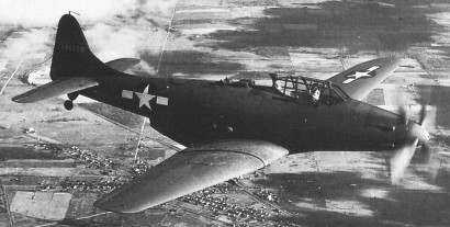
The first XP-75 flew on November 17, 1943. It was powered by an Allison V-3420-19 engine rated at 2600 hp for takeoff and driving a pair of contra rotating propellers. As planned, the wing was of a straight center section with P-40 outer panels with modified tips. The tail assembly was from an A-24, and the main undercarriage members were taken from an F4U Corsair.
The ‘hybrid’ test ships were fol¬lowed by six production XP-75As with bubble canopy rather than the braced hood of earlier machines and a modified tail assembly. The first of these flew on 15 Septem¬ber 1944 and had most compo¬nents designed new from the out¬set. It featured the V-3420-23 engine of the XP-75A.
All six XP-75A long-range escort versions were in the test program by the spring of 1944. Some problems were encountered with instability, since errors had been made in the initial estimate of the aircraft’s center of mass. The coupled Allison engine failed to give its full rated power. The engine cooling was inadequate, aileron forces were excessively high, and the spinning characteristics were poor. Though it could reach a speed of 400 mph, the XP-75 was disappointing in almost every other aspect.
At that stage in the war, the Republic P-47D Thunderbolt and the North American P-51D Mustang were more than adequately fulfilling the long-range escort role, and the USAAF decided that there was no longer any need for a new escort fighter.
Consequently, the USAAF decided to terminate the P-75 development program, and the production contract for the P-75A was cancelled on October 27, 1944. The serial numbers of the six P-75As built were 44-44549/44553.
By the time of contract termination, the first and second P-75A had been delivered to Elgin Field, Florida for tactical suitability trials, the third machine was in the shop being fitted with an experimental intercooler, and the fourth and fifth machines were almost complete.
Although the USAAF no longer had any need for the P-75, it was decided to go ahead and finish these machines and use them for development work. The sixth machine was to be placed in storage and scavenged for spare parts to keep the rest flying. The five production P-75As never completed official performance trials, but enough testing was performed to confirm the fact that the maximum speed was at least 30 mph below that guaranteed by the manufacturer. The third machine received an experimental intercooler installation which permitted substantial increases in engine power.
The improved version was still unsatisfactory and after three Eagles had crashed, the entire program was cancelled on November 8, 1944. Only eight XP-75s and six P-75As were built. The last production P-75A (serial number 44-44553) was on display in the Annex at the Wright-Patterson Air Force Base Museum in Dayton, Ohio, in 1992. This was apparently the aircraft that had been scavenged to keep the other P-75s flying, so more than a few things may be missing. The P-75A on display was loaned to the USAF Museum by the National Air and Space Museum of the Smithsonian Institution in 1977.
XP-75 Engine: Allison V-3420-23, 2885 hp Span: 49 ft. 4 in. Length: 40 ft. 5 in. Height: 15 ft. 6 in. Wing area: 347 sq.ft Empty weight: 11,495 lb Normal loaded weight: 13,807 lb MTOW: 18,210 lb Maximum speed: 404 mph. Max speed: 433 mph at 20,000 ft Cruising speed: 250 mph. Range: 2,600 miles Range max external fuel: 3500 miles Service Ceiling: 29,500 ft. Absolute ceiling: 36,400 ft. Initial climb rate: 4200 fpm at 10,000 ft Climb rate: 3900 fpm at 20,000 ft Crew: One Armament: six 0.50-inch machine guns wings (235 rpm) / four 0.50-in machine guns fuselage (300 rpm) / two 500-pound bombs