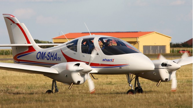
The Fly-Fan Shark is a Slovak light aircraft designed by Frantisek Sustek and under development by Fly-Fan of Trenčín. The design was introduced at the Aero show held in Friedrichshafen in 2007 as a mock up and in 2011 as a flying aircraft. The aircraft first flew on 29 June 2011 and was intended to be supplied as a complete ready-to-fly-aircraft.
The Shark was designed with the goal of providing similar performance to other twin-engined light aircraft, but on 30% less power. It features a cantilever low-wing, a five-seat enclosed cabin, retractable tricycle landing gear and twin wing-mounted engines in tractor configuration.
The aircraft is made from Kevlar and carbon fibre. Its 11.4 m (37.4 ft) span wing employs a Jd 16 (40) 162 airfoil at the wing root, transitioning to a Jd 17 (40) 157 at mid-span and a Jd 15 (35) 136 at the wing tip. The wing has an area of 16.2 sq.m (174 sq ft) and mounts split flaps that can be extended 50 deg. The standard engines fitted are a pair of 160 hp (119 kW) Lycoming O-320-D1A four-stroke powerplants.
The aircraft has an empty weight of 1,221 kg (2,692 lb) and a gross weight of 1,500 kg (3,300 lb), giving a useful load of 279 kg (615 lb).
Engines: 2 × Lycoming O-320-D1A, 120 kW (160 hp) Propellers: 3-bladed MT-Propeller or Hartzell Propeller constant speed, 1.78 m (5 ft 10 in) diameter Length: 8.9 m (29 ft 2 in) Wingspan: 11.4 m (37 ft 5 in) Height: 3.07 m (10 ft 1 in) Wing area: 16.2 m2 (174 sq ft) Airfoil: wing root: Jd 16 (40) 162 airfoil, mid-span: Jd 17 (40) 157, wing tip: Jd 15 (35) 136 Empty weight: 1,221 kg (2,692 lb) Gross weight: 1,500 kg (3,307 lb) Cruising speed: 260 km/h (162 mph; 140 kn) Stall speed: 140 km/h (87 mph; 76 kn) Never exceed speed: 330 km/h (205 mph; 178 kn) Range: 1,600 km (994 mi; 864 nmi) Endurance: 8 hours Maximum glide ratio: 16:1 at 160 km/h (99 mph) Rate of climb: 10.6 m/s (2,090 ft/min) Wing loading: 92.6 kg/m2 (19.0 lb/sq ft) Crew: one Capacity: four passengers
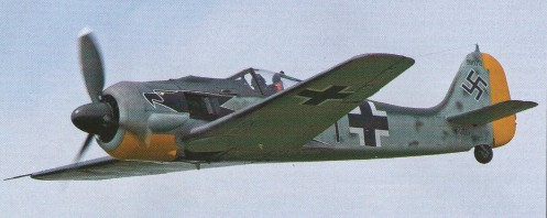
Altogether 20 kits were manufactured, 16 sold to customers. Among them are three kits are as static FW 190 in museums. The flight work crew assembled FW 190 A8/N (D-FWJS), including all corrections and rework of different systems, for a German customer. The oil cooling system received an additional “ring oil cooler. Combustion air of the Ash 82T is sucked in vertical, behind the engine. To give the copied FW 190 as authentic an appearance as possible a rework became necessary, with the help of the additional oil cooler. Further substantial changes concerned the brake linings as well as a variation in type of the brake pumps, which are installed at the pedals.
FW-190A-8
The first flight of the D-FWJS was accomplished by test pilot Klaus Plasa. The flight testing of D-FWJS and D-FWWC without the use of the flap system for takeoff and landing were accomplished. However the flaps were used in the flight, and a “Lastigkeitsänderung” is clearly noticeable around the transverse axis, which could be well trimmed. The FW 190 test flight report written by Professor Kurt Tank, says when driving flaps and undercarriage “Lastigkeitsänderungen” were not produced. In the FW 190 flight work uses in the house developed fin adjustment devices, similarly those for the use in the ME 262 developed trim actuators. Original devices available, but such systems, e.g. original undercarriage introduction engines and Cyclo transmissions were not used for safety safety reasons. The production of the 40’s was shaped by scarcity of raw materials, a large number of these electrical trim engines did not have ball bearings, but only steel sockets, as “emergency substitute solution “. The original drives for the landing flaps this, which was not acceptable for safe flying operation now. Flight testing of the first FW 190A-8/N began in July 2004, and was to continue in 2007 with test pilot Horst Philipp at the controls.
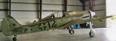
FW 190D-9/N “Dora”
At Gammelsdorf in Upper Bavaria, the Flug Werk company unveiled its first long-nose FW 190D-9/N “Dora”. Substituting for the original Jurno 213A engine is an Allison V-1710 engine, specially modified by Bud Wheeler’s Pen nsylvania- based ACE Competition engines. The Allison unit is 500kg (1,1001b) lighter than the Jurno, so to compensate a specially constructed engine mounting has been manufactured from chrome-molybdenum steel. Wheeler has also extensively modified the reduction gear in order to achieve the same propeller speed as the FW 190A-8, so it will be possible to use the same blades as fitted to the radialengined version. Specially manufactured exhaust pipes will ensure that this area of the 190D will look authentic from the outside.
Three FW 190D-9s will be built, with the first example going to a Florida-based owner once it is completed. The second aircraft is also due to be exported, but the third 190D will be retained by Flug Werk, together with one of the 1 90A-8s, and be used for display and film work.
The first of the Flug Werk FW 190D-9/N Doras was handed over to its owner Tom Blair at Kissimmee, Florida, 11 December 2007.
The AP-51 Palomino structural kit from FlugWerk, named “Palomino” in order to document it’s closeness to the P-51 Mustang, yet make it clearly discernable from the real P-51’s, so the new components do not end up on type certified Mustangs. This is a requirement by the FAA. All of the AP-51 assemblies are manufactured from western materials, such as SAE 2024 and/or SAE 7075 aluminum alloys and SAE 4130 steel alloy, where called for, in high strength applications. The structures are built, following the standards of the original NAA manufacturing drawings and standards. Utilizing CNC-machinery FlugWerk manufacture all brackets, hinges for the tail-gear, all flying surfaces and the landing gear trunnion boxes: All of these new components are better in quality and strength than their sand-casted predecessors from wartime. The trunnion boxes are made using a 5-axis CNC mill. The AP-51 wing profile demands absolute true coordinates, and the jigs which are utilized during the assembly processes are built following today’s aerospace industry standard. Each individual jig employs fold-down templates to assure correct profile conforming surfaces to the smallest fraction of an inch while the entire assembly is under construction. Before the jigs are used for any assembly wrok they are heat treated for the purpose of relieving any stresses that have built up during their welding assembly. The entire jigs are therefore put in a furnace for a given time. After heat-treating the jig’s structures, all critical surfaces are milled to their final dimensions and by that gain the purpose as measuring zero-coordinates. Even the assembly work is done in a climate-controlled environment. The stamped and trued ribs are subject to corrosion proofing, employing the “Alodyne” process, followed by primer coating with two part Epoxy paint prior to assembly. The final result is an airframe that is similar and in some regards better to the original structures.
The AP-51 Palomino airframe kit includes:
Engine mount, with smile but w/o lord mounts
Center fuselage with dog-house, inlet- outlet duct, windshield assembly and firewall with stamped, dished insert. P-51 D style.
Aft fuselage
Vertical stabilizer, with ventral fairing
Rudder ( for fabric covering ) with trim tab and balance weight
Horizontal stabilizer ( standard incidence is set for P-51 D )
Elevators ( for fabric covering ) with trim tab and balance weight, or
Elevators ( metal skinned ) with trim tab and balance weight
Wing, with left and right tip-extensions, body fairings, clamshell- and spade doors
Ailerons, left and right
Flaps, left and right All structures are built using brand new ALCOA/USA supplied aluminum extrusions and AN/MS hardware, also imported from the US. The 2010 price for the airframe kit in US $: 475.000 ex works” Gammelsdorf/Germany.
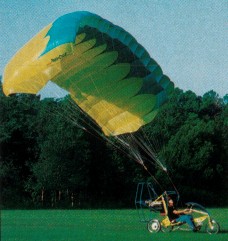
Designed by Orville Lee Floyd III, the Para-Cycle flies as a powered parachute, using a 400 sq.ft rectangular chute from Performance Design Inc, powered by a 40 hp two stroke engine. It pedals on the ground as a three wheel, twenty-one speed tricycle, and drives at up to 15 mph powered by an optional electric hub motor and rechargeable 24 volt battery. The prototype was shown at Oshkosh 1997. On the prototype the pedals are loosened from the bicycle crank and become the parachute foot controls. Robert Baslee of Airdrome Airplanes has teamed with Lee to provide engineering and manufacturing support. The power cage has progressed through several changes. Bike type steering on the ground is conventional with a long-throw handle bar that supports the engine throttle in the left hand and wheel brake and electronic speed control for the optional ground mode electric propulsion in the right hand. The right and left red lines, attached to the disconnected foot pedals on the preproduction prototype, pulls the canopy’s leading edge corners, which controls turns. Changes to be incorporated in the production models included widening the gear track from 47 in to 57 in, lowering the engine 4 in for better ground stability, increasing the airframe tube diameter from 1.25 in to 1.5 in, changing the prop cage from six sided to round. A front hydraulic brake will be optional, the front end length will be customised to the customer, and a larger 452 sq.ft chute will allow up to 250 lb payload. Alternatives to the standard 40 hp 2si 460F-40 engine will be the 50 hp 2si, Rotax 447, and Rotax 503.