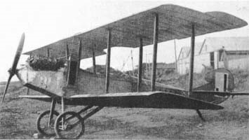
Itoh Emi 13

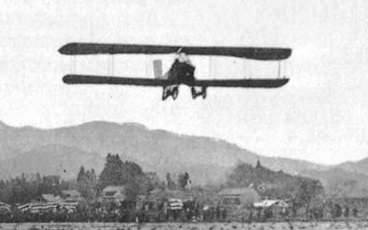
From mid-1919 Otojiro Itoh’s flying school at Itoh Airfield at Tsudanuma had relied heavily on the Itoh Emi 9, its only two-seat trainer. Its designer, Tomotari Inagaki, had already designed a similar but improved successor, powered by the same Hall-Scott V-8 engine. This, the Emi 13, was built between the summer of 1919 and the following spring.

The Emi 13 was a wooden-framed, fabric covered two bay biplane with pairs of parallel interplane struts. Its wings were rectangular in plan, with overhung ailerons only on the upper wing. Tall, outward-leaning cabane struts braced the wing over the fuselage, where there was a broad trailing edge cut-out to increase the field of view from the rear seat. The lower wings were mounted on the lower fuselage longeron.

Its V-8 engine was nose-mounted with its upper parts exposed and a flat, narrow, rectangular radiator attached vertically just behind it on the port side where the engine cowling joined a flat-sided fuselage. The two separate cockpits of the Emi 5 were replaced by tandem seats in a single open cockpit, with the student under the central wing and the tutor under the trailing edge. This change was made to ease communication between them. Behind them the fuselage had rounded upper decking. The tail was conventional, with the horizontal surfaces mounted on top of the fuselage and the tailplane strut-braced from below. The fin was small and triangular in profile but carried a large rounded rudder with a prominent horn balance.

The Emi 13 had a single axle undercarriage with large wheels. The axle was rubber-sprung on a cross-braced frame with forward legs and trailing drag struts to the lower fuselage longerons. Its tall tailskid was mounted below the tailplane leading edge.

First flying c. May 1920, to demonstrate its abilities the Emi 13 took part in a competition sponsored by the Imperial Flying Association held In August 1920 in Tokyo. It gained the fourth prizes for both speed, at 109 km/h (68 mph; 59 kn) and altitude 1,370 m (4,490 ft).

By late 1920 the Hall-Scott engine was reaching the end of its life so Inagaki revised the design to take a 90 hp (67 kW) Curtiss OX-5, another water-cooled V-8. Itoh completed this aircraft, referred to as the Emi 13 no.2, in 1921 and it became the principal trainer at the flying school.

Engine: Hall-Scott V-8, 80 hp
Propeller: 2-bladed wooden
Wingspan: 10.37 m (34 ft 0 in)
Wing area: 29 m2 (310 sq ft)
Length: 6.40 m (21 ft 0 in)
Height: 2.50 m (8 ft 2 in)
Empty weight: 450 kg (992 lb)
Gross weight: 600 kg (1,323 lb)
Maximum speed: 106 km/h (66 mph, 57 kn)
Cruise speed: 95 km/h
Endurance: 2 hr
Time to1,000 m (3,300 ft): 7 min
Crew: one tutor
Capacity: one student
Itoh Emi 9

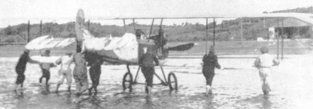
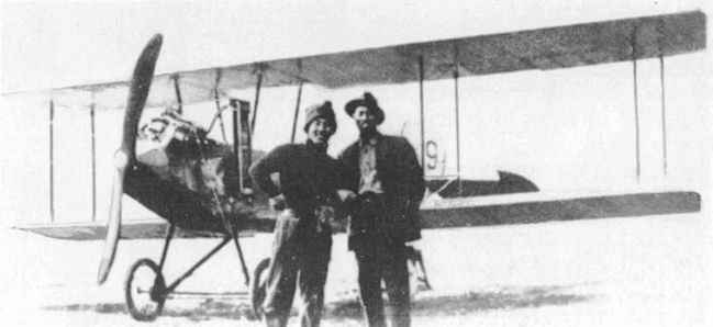
After the destruction of Itoh’s hangar at Inage Beach by a tidal wave at the end of September 1917 his works and flying school moved to Tsudanuma Beach, otherwise known as Itoh Airfield. The move led a significant increase in student numbers and a new, two seat trainer was needed; until then they had relied on single-seaters. The solution was provided not by Itoh or his employees but by a regular visitor to the airfield, Tomotari Inagaki. He designed a simple and stable two seat trainer around the water-cooled 80 hp (60 kW) Hall-Scott V-8 engine taken from the Emi 3. It became known as the Itoh Emi 9.

The Emi 9, typical of its time, had a wooden frame and fabric covering. It was a straightforward two bay biplane, with two parallel pairs of interplane struts on each side. The wings were rectangular in plan and manufacture was further simplified by the absence of dihedral or stagger.

Its upright V-8 engine was installed in the nose with most of the upper part exposed and its rectangular radiator mounted edge-on just behind the engine on the fuselage port side. Pupil and instructor had separate open cockpits in a fuselage rather similar to that of the Emi 5. Its tail was with a triangular fin, a rudder with a straight leading edge which continued that of the fin and a deep, rounded trailing edge, though the control surfaces had horn balances, the first to be used on a Japanese civil aircraft.

The Emi 9 had a simple, single axle undercarriage with legs on the lower fuselage longerons and trailing drag struts to the fuselage centre line.

Built in 1918 the Emi 9 served the Itoh school as intended, though details of its history are lacking.

Powerplant: 1 × Hall-Scott, 60 kW (80 hp)
Propeller: 2-bladed
Wingspan: 9.80 m (32 ft 2 in)
Length: 7.45 m (24 ft 5 in)
Height: 2.30 m (7 ft 7 in)
Empty weight: 350 kg (772 lb)
Maximum speed: 111 km/h (69 mph, 60 kn)
Crew: one instructor
Capacity: one student

Itoh Emi 3

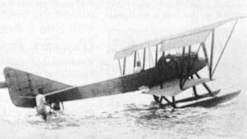
Though by around 1916 demonstration flights by early Japanese aircraft were beginning to be commercially viable, there were no suitable seaplanes. Otojiiro Otoh, who had designed and built Japan’s second commercial landplane, the Itoh Emi 1, was encouraged to fill the gap. The result was the Emi 3, completed in August 1917.

Like most aircraft of its time, it was a wooden-framed and fabric covered biplane. It was a two-bay design with wings braced by two pairs of parallel, vertical interplane struts on each side but, as the upper wing had a significantly longer span, there was also pairs of parallel, outward- leaning struts to brace the overhang. Only the upper wings carried ailerons.

Its water-cooled 80 hp (60 kW) Hall-Scott V-8 engine drove a two-bladed propeller. Close behind it there was an open cockpit for one passenger; the pilot’s cockpit was just aft of the upper wing trailing edge. The Emi 3’s fuselage was flat-sided and quite slender, with the horizontal tail mounted on its top. Its fin had a triangular profile and carried a rudder of roughly parallelogram profile.

It had twin floats, mounted with a pair of single struts to the fuselage forward and a transverse W-form strut to the fuselage and lower wing aft.

The Emi 3 was built at Itoh’s Inage Beach site and, assisted by Toyokichi Daiguchi and Toyotaro Yamagata, and with the help of student pilots, the aeroplane was completed in August 1917. Flight tests by several pilots found its performance, stability and handling were good.

Test flights over, the Emi 3 was taken by rail to Osaka. In preparation for demonstration flights, the Emi 3 Seaplane was assembled and maintained in a hangar located on the beach at Nishinomiya, just west of Osaka. Spectators’ fees made these flights a commercial success for Japan’s first passenger-carrying floatplane. Itoh named the only example Seagull (Kamome, かもめ).

Powerplant: 1 × Hall-Scott water-cooled V8, 60 kW (80 hp)
Propeller: 2-bladed wooden
Upper wingspan: 15.41 m (50 ft 7 in)
Wing area: 46.5 sq m (501 sq ft)
Length: 7.27 m (23 ft 10 in)
Height: 4.51 m (14 ft 10 in)
Empty weight: 580 kg (1,279 lb)
Maximum speed: 43kt (50mph)
Crew: one
Capacity: one passenger

Itoh Emi 2

Itoh Emi 2

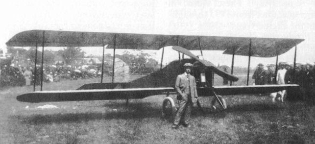
By early 1917 Itoh had begun the design of a new aircraft. The Emi 2 owed much to its predecessor, both biplanes with wooden structures and fabric covering. Rectangular plan wings, shorter in span by 2.50 m (8.2 ft) and using a lower drag profile than before, were braced with pairs of parallel interplane struts, though the Emi 2, a two-bay biplane, had one less bay on each side. The Emi 2’s upper wing had a slightly greater span than the lower one, which had more rounded tips. The centre of the upper wing was supported over the fuselage by four parallel cabane struts. As on the Emi 1 there were ailerons, with chords which increased outwards, only on the upper wings.

The Emi 2 also inherited its predecessor’s engine, the 26–34 kW (35–46 hp) Grégoire Gyp. The flat-side fuselage had an open cockpit for the pilot; a semi-circular cut-out in the upper trailing edge increased the pilot’s upward field of view. The long span horizontal tail was roughly rectangular in plan and mounted on the upper fuselage and the vertical tail also was also parallel-sided, though with a sloping top.

The Emi 2’s wide track landing gear had two, rather than four wheels, each on a landing leg with bungee cord shock absorbers.

It flew for the first time in April 1917.

From May 1917 Itoh gave a series of demonstration flights from his east Inage Beach base, culminating in a visit to his home town of Osaka in September. His timing was fortunate, as his Inage Beach hangar was flattened by a typhoon-related tidal wave at the end of the month, while t Emi 2he was away. Demonstration flights resumed until the Emi 2 began use as a trainer from Itoh’s new base at Tsudanuma Beach.

Its last operations were under new owners based near Hammamatsu. It was again used for demonstration flights, piloted by the inexperienced Asao Fikunaga aound Osaka from August 1919. One flight took him to his home town of Toyonaka but the Emi 2 overturned on landing and was badly damaged. It was rapidly repaired but in May 1920, leaving Osaka, the aircraft hit a house roof, ending its career.

Powerplant: 1 × Grégoire Gyp, 26–34 kW (35–45 hp)
Propeller: 2-bladed
Maximum speed: 85 km/h (53 mph, 46 kn)
Wingspan: 9 m (29 ft 6 in)
Wing area: 25 m2 (270 sq ft)
Height: 2.25 m (7 ft 5 in)
Empty weight: 250 kg (551 lb)
Crew: one

Itoh Emi 1

By early 1915 Otijiro Itoh had established the Itoh Aeroplane Research Studio and an associated flying school and by that autumn had completed his first design, the Emi 1. The “Emi” was a respectful nod to the district of Osaka where he grew up.

The sole Emi 1 was a three-bay biplane with a fabric covered wooden structure. Its wings were of equal span and joined by parallel pairs of interplane struts. The upper wing was well above the fuselage and the lower ones mounted on the lower fuselage longerons. The Hyabusa-go’s French, 35–45 hp (26–34 kW) Grégoire Gyp four cylinder, water-cooled inline engine powered it. Its pilot had an open cockpit. At a time when there were few prepared airstrips, landing gear needed to be robust and the Emi 1’s gear had two wheels on each leg.

Its first flight was on 11 November 1915.

On 8 January 1916, not long after the first flight, Itoh flew the Emi 1 from his base at Inage Bay to Tokyo. This took 55 minutes and was the first flight to Tokyo. He later flew it to 58 Japanese cities, partly to advertise his aircraft and partly to raise air-mindedness in Japan. The Emi 1 was the second successful Japanese aircraft, following the Narahara 4 ”Ohtori-go”.

Later the Emi 1 was re-engined at Inage Bay with a 50 hp (37 kW) Hino Type, remaining in use with the flying school.

Emi 1
Powerplant: 1 × Grégoire Gyp 26–34 kW (35–45 hp)
Propeller: 2-bladed fixed-pitch
Wingspan: 11.50 m (37 ft 9 in)
Wing area: 33 m2 (360 sq ft)
Length: 6.65 m (21 ft 10 in)
Height: 2.50 m (8 ft 2 in)
Empty weight: 350 kg (772 lb)
Maximum speed: 76 km/h (47 mph, 41 kn)
Crew: one

I-TEC Maverick

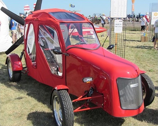
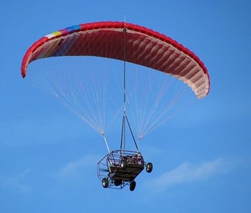
The I-TEC Maverick is a powered parachute aircraft with a roadable fuselage. Equipped with the largest powered parachute certified by the FAA, the Maverick received experimental aircraft airworthiness certification on April 14, 2008, with N-Number 356MV.

prototype flight

Capable of interstate speeds on pavement, the Maverick’s dune buggy-like frame of chromoly tubing gives it the ability to be used off-road. Additionally, the vehicle can deploy a parafoil and fly as a powered parachute, it weighs about 1100 pounds and has a useful carrying capacity equivalent to a Cessna 172 (fuel and 550 pounds cargo). With a 22-foot mast, the Maverick can take off and land in weather conditions that other powered parachutes would not be able to safely operate in. Steve Saint has said he envisions the Maverick being useful to the Huaorani and other Indian groups, farmers and ranchers, pipeline inspection crews and anyone else with a requirement to traverse rough, roadless ground. Popular Mechanics gave it their Breakthrough Award in 2009. In 2012, the Maverick was accepted by the United States FAA to operate as an Experimental homebuilt, S-LSA, or E-LSA.

Variants:

Maverick URVATV (Ultimate Roadable, All-Terrain, Aerial Vehicle)
Initial model

Maverick HPAV (High Performance Aerial Vehicle)
Transaxle removed, fan drive only

Maverick HPRATV (High-Performance, Roadable, All-Terrain Vehicle)
Wheel drive only, convertible to flight.

Maverick XTRV (Xtreme Roadable Vehicle)
300 hp (224 kW) wheel drive only.

Specifications:
Engine: 1 × 2.5l Subaru Four cylinder, 190 hp (140 kW)
Propeller: 5-bladed Warp Drive
Cruise speed: 35 kn; 64 km/h (40 mph)
Endurance: 3 hours
Service ceiling: 10,000 ft (3,000 m)
Rate of climb Crew: 1
Capacity: 1
ROC: 600 ft/min (3.0 m/s)

IST/PAF ARDA XL-17 Musang

The XL-17 ” Musang” (Wildcat) is the fourth aircraft in the series designed and constructed by the Institute of Science and Technology of Manila in the Philippine Republic, and is part of a programme to test the application of local materials, such as home-grown woods, to aircraft structure. During their experiments the Institute developed a material which it called “Wobex”. “Wobex” consists of diagonally woven strips of thin bamboo glued together, made air tight and leakproof, and finished on the surface with a layer of fine sawdust and glue. Its main use is as a stressed skin covering.

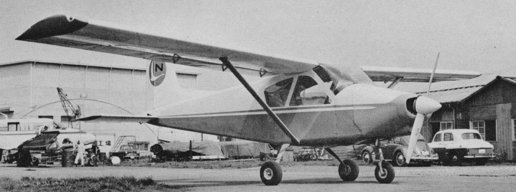
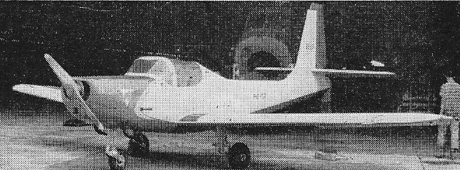
In the mid-1950s the Philippine Institute of Science and Technology (I.S.T.) designed the single engine, tricycle undercarriage, low wing monoplane L-17 was one of them.

Designed by Antonio J. de Leon, its wing was a single-piece wooden structure with 5° of dihedral and a straight-tapered plan. It was plywood-covered and had split flaps inboard of the ailerons. The cantilever tail unit was similarly constructed with the straight-tapered horizontal surfaces on top of the extreme aft fuselage; the single-piece elevator carried an offset trim tab. The vertical tail was tall and straight-edged; the bottom of the horn balanced rudder was above the elevator and just aft of its hinge, with a small cut-out to allow for elevator deflection.

Fuselage is a one-piece semi-monocoque structure with wooden bulkheads and stringers covered by a “Wobex ” skin, which in turn is covered with fabric for final finishing and polishing. Fuel tanks are fitted aft of the seats and the rest of the fuselage space can be used as either a radio compartment or as baggage space. The engine mount is the standard truss-type with attachments at four points to the firewall bulkhead, which is reinforced for the attachment of the nose landing gear. The cantilever wing is trapezoid in form and of one-piece construction that tapers in chord and length. It is made up of one main and one auxiliary spar of box-type construction and reinforced diagonal spar. The leading edge is covered with a thick plywood covering to take torsional and chordwise shear loads. Overall wing covering is fabric. Slotted type ailerons are fitted and simple split flaps are located under the wings between the ailerons and the fuselage. The wing root upper section upper covering is reinforced to serve as a step and walkway to the cockpit. A tricycle undercarriage is fitted, the main gear to the main wing spars and the nose gear to the firewall bulkhead.

Cockpit seating two side by side under a single piece canopy. A 108 hp (80 kW) Lycoming O-235-C1 flat-four engine drove a two-blade propeller. The fixed tricycle undercarriage had rearward-sloping oleo legs mounted to the wings, giving a track of 2.40 m (7 ft 10 in).

The first flight of the L-17 was scheduled for May 1956.

Engine: 1 × Lycoming O-235-C1, 81 kW (108 hp)
Propeller: 2-bladed , fixed pitch, wooden
Wingspan: 9.60 m (31 ft 6 in)
Wing area: 13.40 m2 (144.2 sq ft)
Airfoil: US 35B at root, NACA 23012 tip
Length: 7.20 m (23 ft 7 in)
Height: 3.20 m (10 ft 6 in)
Empty weight: 510 kg (1,124 lb)
Gross weight: 735 kg (1,620 lb)
Fuel capacity: 68 L (15 Imp gal, 18 US gal)
Maximum speed: 210 km/h (130 mph, 110 kn)
Cruise speed: 175 km/h (109 mph, 94 kn)
Stall: 80 kph
Rate of climb: 3.8 m/s (750 ft/min)
Crew: 2

IST/PAF ARDA XL-15 Tagak

In the early 1950s in the Philippines, the Institute of Science and Technology (I.S.T., previously known as the Bureau of Science) designed at least three different prototypes, both to investigate the scope for local aircraft design and production and to examine the use of indigenous materials in their construction. One such material of interest was Wobex (Woven bamboo experimental), a reinforced woven bamboo.

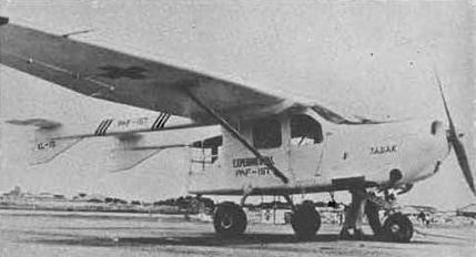
The XL-15 Tagak was the second of these prototypes, developed in collaboration with the Philippine Air Force, it was designed by Antonio J. de Leon as a utility, liaison or ambulance aircraft and as a test bed for the use of local materials in aviation. It was a single-engine, high-wing monoplane with a twin-boom layout and tricycle undercarriage to enable easy access to the fuselage pod via rear doors. The inner wing sections, fitted with slotted flaps on the trailing edges had constant chord but further out the wings tapered, with slotted ailerons. There was a single lift strut on each side between wing and lower fuselage, with an airfoil profile to add to the lift from the wings.

The fuselage of the Tagak was a wood and plywood framed semi-monocoque skinned with Wobex and ply. Its cabin, behind the 185 hp Lycoming flat six engine, was 3.26 m (10 ft 6 in) long to the rear of the pod. There were two front seats under the wing leading edge, two more behind and room for one or two (stacked) stretcher cases. The cabin had two windows on each side and the rear part of the pod, which projected behind the wing trailing edge, was also extensively glazed. The two tail booms, of all ply construction, were integral with the wing centre section. The fins, with long chord underside fillets, were integral with the booms. The tailplane was rectangular and extended beyond the fins, carrying a horn balanced elevator. The fixed surfaces were of wood and ply construction, with Wobex covering; control surfaces were fabric covered.

Flight testing of the Tagak began in October 1954. By 1956 some small modifications had been made: rudder area was increased and a shimmy-damper added to the nosewheel leg.

Only one was built.

Engine: 1 × Lycoming O-425A, 138 kW (185 hp)
Propeller: 2-bladed fixed pitch
Wingspan: 12.0 m (39 ft 4 in)
Wing area: 20.30 m2 (218.5 sq ft)
Airfoil: NACA 23012 (inner section), USA 35B outer section
Length: 9.15 m (30 ft 0 in)
Height: 2.80 m (9 ft 2 in)
Empty weight: 780 kg (1,720 lb)
Gross weight: 1,250 kg (2,756 lb)
Fuel capacity: 174 L (38 Imp gal, 46 US gal)
Maximum speed: 200 km/h (120 mph, 110 kn)
Cruise speed: 158 km/h (98 mph, 85 kn)
Range: 675 km (419 mi, 364 nmi)
Service ceiling: 4,000 m (13,000 ft)
Rate of climb: 3.0 m/s (590 ft/min)
Seats: 4

IST/PAF ARDA XL-10B Balang / Grasshopper

The XL-10B Balang (Grasshopper) was a powered glider joint project of Institute of Science and Technology (IST) and Philippine Air Force (PAF) Air Research and Development Authority (ARDA).

It first flew in 1953.

Engine: 20 hp
Wingspan: 12 m
Length: 5.20 m
Height: 1.5 m
Aspect ratio: 8.1
Wing area: 17.8 sq,m
Empty weight: 185 kg
Loaded weight: 280 kg
Max speed: 125 kph
Cruise speed: 72-80 kph
Stall: 49 kph
Glide speed: 75 mph