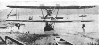
As part of frantic efforts to catch up with aviation in the rest of the world, a variety of design were hastily developed. Among these was the Beeng, quite possibly the first fighter ever designed in China. The Beeng a tractor flying boat, carrying a crew of three – a pilot and two gunners. Free space in the hull could carry either extra ammunition or small bombs to be dropped by hand. As a secondary role, the aircraft could be quickly converted for use as a passenger plane. In the space where ammunition or bombs would be carried, four seats could be installed for passengers. While the design itself was domestic, China couldd not hope to develop suitable engines, so a 360hp Rolls-Royce 12-cylinder liquid cooled engine was used. The aircraft itself was 39 feet long, 16 feet tall, and had a wingspan of 56 feet. Details of its service, however, are unclear.
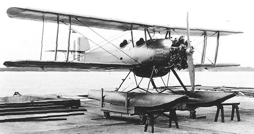
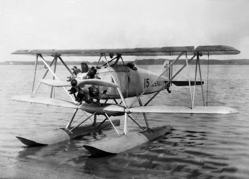
The Naval Air Establishment Chiang Hung (江鴻 – “River Swan”) was a reconnaissance seaplane developed for the Chinese Navy.
First flown in July 1931, it was a conventional biplane design with single-bay, unstaggered wings of equal span and accommodation for the pilot and observer in tandem, open cockpits. The landing gear consisted of twin pontoons. Only two were built, by the Shanghai Naval Air Establishment.
Powerplant: 1 × Wright Whirlwind, 123 kW (165 hp) Length: 8.33 m (27 ft 4 in) Wingspan: 10.87 m (35 ft 8 in) Height: 3.55 m (11 ft 8 in) Empty weight: 740 kg (1,628 lb) Gross weight: 1,180 kg (2,596 lb) Crew: Two
The 1918 N-1 USN gunship was a two place open cockpit, biplane flying boat. A twin-boom, triple-tail aircraft with a nacelle fuselage, a 37mm cannon was fitted in the nose.
Two were built, A4341 and 4342, and a contract for 2,284 was cancelled.
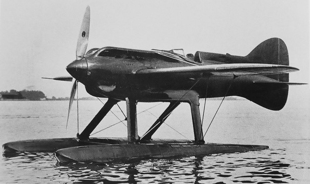
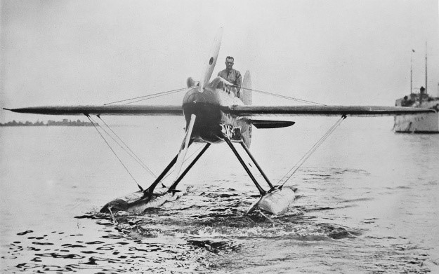
Al Williams in the 1929 Mercury-Packard Schneider Trophy Racer – did not race
In 1927, Lt. Alford Joseph Williams and the Mercury Flying Corporation (MFC) built the Kirkham-Williams Racer to compete in the Schneider Trophy contest. Although demonstrating competitive high-speed capabilities, the aircraft had handling issues that could not be resolved in time to make the 1927 race. Williams, backed by the MFC, decided to build on the experience with the Kirkham-Williams Racer and make a new aircraft for an attempt on the 3 km (1.9 mi) world speed record.
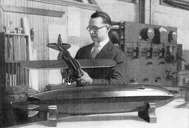
R. Smith, chief draftsman of the wind tunnel at the Washington Navy Yard, holds a model of the original landplane version of the Williams Mercury Racer. Lt. Al Williams was originally not focused on the Schneider Trophy contest but was later convinced to enter the event.
Although there was no official support from the US government, the US Navy indirectly supported Williams and the MFC’s continued efforts to build a new racer. Williams’ previous racer was designed and built by the Kirkham Products Corporation. However, Williams felt that Kirkham lacked organization, and he was not interested in having the company build another aircraft. Williams had already shipped the previous racer to the Naval Aircraft Factory (NAF) to undergo an analysis on how to improve its speed. With the Navy’s support, the NAF was a natural place to design and build the new racer, which was called the Williams Mercury Racer. The aircraft was also referred to as the NAF Mercury and Mercury-Packard.
In mid-1928, a model of the Williams Mercury Racer landplane was tested in the wind tunnel at the Washington (DC) Navy Yard. However, the decision was made to design a pair of experimental floats and test them on the aircraft, since there was a pressing need to explore high-speed seaplane float designs. It appears all subsequent work on the aircraft was focused on the seaplane version. Williams did not originally intend the Williams Mercury Racer to be used in the 1929 Schneider race. But the US had won the Schneider Trophy two out of the last four races, and another win would mean permanent retention of the trophy. With the Williams Mercury Racer now a seaplane, Williams relented to pressure and agreed to work toward competing in the 1929 Schneider Trophy contest and to attempt a new speed record.
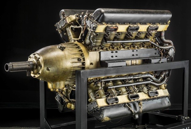
The Packard X-2775 engine installed in the Williams Mercury Racer was actually the same engine originally installed in the Kirkham-Williams Racer. It has been updated with a propeller gear reduction, new induction system, and other improved components. This engine is in storage at the Smithsonian National Air and Space Museum.
Under the supervision of John S. Kean, work on the racer began in September 1928 at the NAF’s facility in Philadelphia, Pennsylvania. On first glance, the Williams Mercury Racer appeared to be a monoplane version of the previous Kirkham-Williams Racer. While some parts such as the engine mount and other hardware were reused, the rest of the aircraft was entirely new. The Williams Mercury Racer was powered by the same Packard X-2775 engine (Packard model 1A-2775) as the Kirkham-Williams Racer, but the engine had been fitted with a .667 propeller gear reduction, and its induction system had been improved. The 24-cylinder X-2775 was rated at 1,300 hp (969 kW), and it was the most powerful engine then available in the US. The X-2775 was water-cooled and had its cylinders arranged in an “X” configuration.
Packard 1A-2775 Engine No. 1 in its most modified version, with high compression, reduction gear and late type cylinder banks, was used in the Naval Aircraft Factory Mercury racing plane with engine 1A-2775, Serial No. 1, Bureau No. 10960, as a U. S. entry in the 1929 Schneider Trophy.
The engine turned a ground adjustable Hamilton Standard propeller that was approximately 10 ft 3 in (3.12 m) in diameter. A Hucks-style starter driven by four electric motors engaged the propeller hub to start the engine. Carburetor air intakes were positioned just behind the propeller and in the upper and lower Vees of the engine. The intakes faced forward to take advantage of the ram air effect as the aircraft flew.
The Williams Mercury Racer consisted of a monocoque wooden fuselage built specifically to house the Packard engine. The racer’s braced mid-wing was positioned just before to cockpit. The wing’s upper and lower surfaces were covered in flush surface radiators. A prominent headrest fairing tapered back from the cockpit to the vertical stabilizer, which extended below the aircraft to form a semi-cruciform tail. A nine-gallon (34 L) oil tank was positioned behind the cockpit. The wings and tail were made of wood, while the cowling, control surfaces, and floats were made of aluminum.
Streamlined aluminum fairings covered the metal struts that attached the two floats to the racer. The underside of the floats had additional surface radiators, which provided most of the engine cooling while the aircraft was in the water at low speed. However, the radiators were somewhat fragile and required gentle landings. The floats housed a total of 90 gallons (341 L) of fuel. Some sources state the fuel load was 147 gallons (556 L). The Mercury Williams Racer had an overall length of approximately 27 ft 6 in (8.41 m). The fuselage was 23 ft 7 in (7.19 m) long, and the floats were 19 ft 8 in (5.99 m) long. The wingspan was 28 ft (8.53 m), and the aircraft was 11 ft 9 in (3.58 m) tall. The racer’s forecasted weight was 4,200 lb (1,905 kg) fully loaded. The Williams Mercury Racer had an estimated top speed of around 340 mph (547 km/h). The then-current world speed record stood at 318.620 mph (512.776 km/h), set by Mario de Bernardi on 30 March 1928.
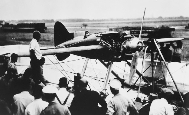
Lt. Al Williams sits in the cockpit of the Williams Mercury Racer during an engine test. The Hucks-style starter is engaged to the propeller hub of the geared Packard X-2775 engine. Note the ducts above and below the spinner that deliver ram air into the intake manifolds situated in the engine Vees.
The completed Williams Mercury Racer debuted on 27 July 1929. On 6 August, the aircraft was shipped by tug to the Naval Academy in Annapolis, Maryland for testing on Chesapeake Bay. Initial taxi tests were conducted on 9 August, and a top speed of 106 mph (171 km/h) was reached. The first flight was to follow the next day, and Williams had boldly planned to make an attempt on the 3 km (1.9 mi) world speed record on either 11 or 12 August. To that end, a course had been set up, and timing equipment was put in place. However, it was soon discovered that spray had damaged the propeller. The propeller was removed for repair, and the flight plans were put on hold.
Although not disclosed at the time, the aircraft was believed to be 460 lb (209 kg) overweight. Williams found that the floats did not have sufficient reserve buoyancy to accommodate the extra weight. The spray that damaged the propeller was a result of the floats plowing into the water. Williams found that efforts to counteract engine torque and keep the aircraft straight as it was initially picking up speed made the left float dig into the water and create more spray. Williams consulted with retired Navy Capt. Holden Chester Richardson, a friend and an expert on floats and hulls. Richardson recommended leaving all controls in a neutral position until a fair amount of speed had been achieved. As the aircraft increased its speed, the water’s planing action on the floats would offset the torque reaction of engine and right the aircraft.
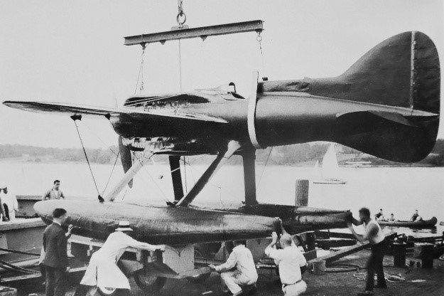
The racer being offloaded from the tug and onto beaching gear at the Naval Academy in Annapolis, Maryland. The rudder extended below the aircraft and blended with the ventral fin. Note how the fairings for the lower cylinder banks blended into the float supports.
Weather and mechanical issues delayed further testing until 18 August. Williams lifted the Williams Mercury Racer off the water for about 300 ft (91 m) while experiencing a bad vibration and fuel pressure issues. After the engine was shut down, the prop was found damaged again by spray. Like with Williams’ 1927 Schneider attempt, time was quickly running out, and the racer had yet to prove itself a worthy competitor to the other Schneider entrants. Three takeoff attempts on 21 August were aborted for different reasons, the last being a buildup of carbon monoxide in the cockpit that caused Williams to pass out right after he shut off the engine. Attempts to fly on 25 August saw another three aborted takeoffs for different reasons.
The general consensus was that the aircraft’s excessive weight and insufficient reserve buoyancy prevented the racer from flying. With time running out, one final proposal was offered. The Williams Mercury Racer could be immediately shipped to Calshot, England for the Schneider contest, set to begin on 6 September. While en route, a more powerful engine and new floats would be fitted. It is unlikely that the more powerful engine incorporated a supercharger, as supercharger development had given way to the gear reduction used on the X-2775 installed in the Williams Mercury Racer. The gear reduction was interchangeable between engines, but it is not clear what modification had been done to the second X-2775 engine at this stage of development. Regardless, the improved Mercury Williams Racer would then be tested before the race, and, assuming all went well, participate in the event. However, given all the failed attempts at flight and the very uncertain capabilities of the aircraft, the Navy rescinded its offer to transport the racer to England.
The Williams Mercury Racer was shipped back to the NAF at Pennsylvania. Williams wanted to install the more powerful engine, which had already been shipped to the NAF, and make an attempt on the 3 km record. The Williams Mercury Racer arrived at the NAF on 1 September 1929, but no work was immediately done on the aircraft. The Navy had not decided what to do with Williams or the aircraft. At the end of October, the Navy gave Williams four months to rework the racer, after which he would be required to focus on his Naval duties and go to sea starting in March 1930.
Studies were made to decrease the Williams Mercury Racer’s weight and improve the aircraft’s cooling system. It was estimated that the suggested changes would lighten the aircraft by 400 lb (181 kg). When the four months were up on 1 March 1930, Assistant Secretary of the Navy for Aeronautics David S. Ingalls felt that enough time, effort, and energy had been spent on the racer and ordered all work to stop. Ingalls also ordered Williams to sea duty. This prompted Williams to resign from the Navy on 7 March 1930. Williams had spent nearly all of his savings on his two attempts at the Schneider contest and knew that the MFC and the Navy had also made a substantial investment in the racer. He wanted to see the project through to some sort of completion, even if it did not result in setting any records.
No more work was done on the Williams Mercury Racer. In April 1930, Williams testified before a subcommittee of the Senate Naval Affairs Committee regarding the racer, his resignation, and other Navy matters. During his testimony, he stated that he wanted another year to finish the aircraft. This time frame would have made the racer ready for the 1931 Schneider Trophy contest, but even in perfect working order it probably would not have been competitive. Williams said the aircraft was 880 lb (399 kg) overweight and that this 21% of extra weight was the reason it could not takeoff. The racer actually weighed 5,080 lb (2,304 kg), rather than the 4,200 lb (1,905 kg) forecasted. Williams said he was initially told that it weighed 4,660 lb (2,114 kg), which was 460 lb (209 kg) more than expected. But Williams thought they could get away with the extra weight. It was only when Williams requested the aircraft to be weighed upon its return to the NAF that its true 5,080-lb (2,304-kg) weight was known.
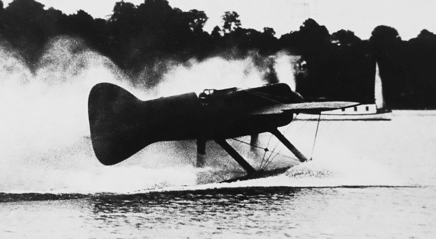
The Williams Mercury Racer being towed in after another disappointing test on Chesapeake Bay. Williams stands in the cockpit, knowing his chances of making the 1929 Schneider contest are quickly fading. Note the low position of the floats in the water.
Williams stated that he wanted to take the Williams Mercury Racer to England even if it was not going to be competitive or even fly. Williams said, “I felt we should see it through no matter what the outcome was. If she would not fly over there—take this, to be specific—I was just going to destroy the ship. It could have been done very easily on the water. I intended to smash it up; but I did intend and [was] determined to get to Europe with it. It made no difference to me what the ship did.”
Ingalls also testified before the committee. He had been involved with the Williams Mercury Racer, was a contributor to the MFC, and had friends who were also contributors. Ingalls said that Williams had informed him about the possibility of crashing the Williams Mercury Racer in England if it was unable to fly. Ingalls said that it was ridiculous to send an aircraft to England that may not be able to fly just so that it could be crashed. It was this consideration that led him to withdraw Navy support for sending the aircraft to England. Ingalls also said that of the aircraft’s extra 880 lb (399 kg), around 250 lb (113 kg) was from the NAF’s construction of the aircraft, and around 600 lb (272 kg) was from outside sources, such as Packard for the engine and Hamilton Standard for the propeller. Ingalls reported that Williams supplied the engine’s and propeller’s weight to the NAF, but those values have not been found. Perhaps the original engine weight supplied to the NAF was for the lighter, direct-drive engine and smaller propeller—the combination installed in the Kirkham-Williams Racer.
On 24 June 1930, the Navy purchased the Williams Mercury Racer from the MFC for $1.00. Reportedly, $30,000 was invested by the MFC with another $174,000 of money and resources from the Navy to create the aircraft. It is not clear if the Navy’s investment was just for the Williams Mercury Racer, as the Packard X-2775 engine was also used in the earlier Kirkham-Williams Racer. The Navy stated they acquired the racer for experimental purposes, but nothing more was heard about the aircraft, and the Mercury Williams Racer faded quietly into history.
Williams taxis the racer in a wash of spray, most likely damaging the propeller again. Note how the floats are almost entirely submerged, especially the left float. The aircraft being very overweight severely hampered its water handling.
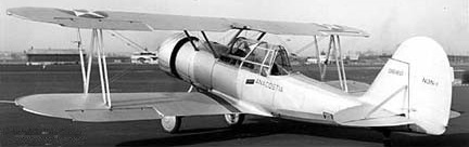
The sole XN5N-1 (1521) of 1941 was a two place, open cockpit, low wing monoplane advanced trainer, with retractable undercarriage. A cockpit canopy was added later.
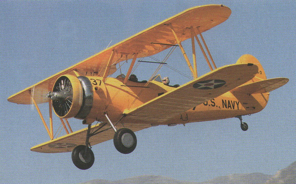
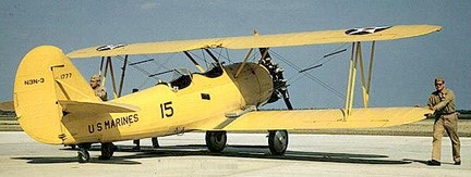
Designed for the US Navy in 1934, and outwardly similar to the service’s current Consolidated NY-2 and -3, the N3N featured an all-metal primary structure covered with fabric except along the fuselage sides, which featured removable alloy panels. The XN3N-1 prototype, 9991, flew in August 1935 with a 164-kW (220-hp) Wright J-5 radial, an engine that was out of production but stocked in considerable numbers.
XN3N-1
The prototype was evaluated as a landplane and floatplane, resulting in a 1935 order for 179 N3N-ls (0017/0101, 0644/0723, 0952/0966), at about $25,000 unit cost. The N3N-1S was a single-float version.
The XN3N-1 became an N3N-1.
NAF N3N-1 0680
Single XN3N-2 (0265) in 1936 and XN3N-3 (N3N-1 conversion 0020) prototypes were used to evaluate the 179-kW (240-hp) R-760-96 engine that was then used in the last 20 N3N-ls and retrofitted in the earlier aircraft.
There followed, in 1940, 816 N3N-3s (1759/1808, 1908/2007, 2573/3072, 4352/4517) with a revised tail and modified landing gear, and the N3Ns were amongst the Navy’s most important wheel- and float-equipped primary trainers throughout World War II.
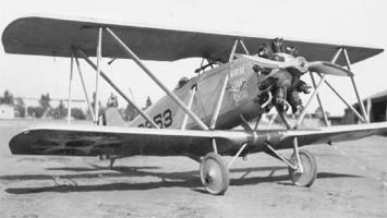
Rex Buren Beisel of the Naval Aircraft Factory desiggned a simple fighter powered by a 200 hp (150 kW) Lawrance J-1 air-cooled radial engine. Its boxy fuselage was suspended between the upper and lower wings (essentially having both dorsal and ventral sets of cabane struts), with the center area of the lower wing enlarged to accommodate a fuel tank.
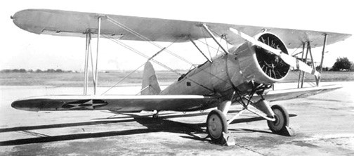
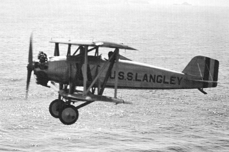
First flying on August 10, 1921, the TS biplane fighter was the first aircraft designed specifically for the US Navy to be used with aircraft carriers. At the NAF plant, five TS-1 (A6300- 6304) aircraft were built to assess the accuracy of the calculations of the contracting companies for payment for the work they had performed.
The NAF provided Curtiss with the plans to build the aircraft, and the result, designated TS-1, arrived at Anacostia on May 9, 1922. The TS-1 from Curtiss was delivered with wheels, so the NAF also designed wooden floats to enable their use on vessels other than aircraft carriers. Testing went well, and in late 1922 the Navy ordered 34 planes from Curtiss, with the first arriving on board the USS Langley (CV-1) in December. The NAF built another five themselves, as a test of relative costs, as well as four more used to experiment with water-cooled inline engines.
Curtiss TS-1
In addition to operating from the carrier deck, the TS-1s served for several years in floatplane configuration aboard destroyers, cruisers, and battleships. The aircraft were slung over the side by crane. Squadron VO-1 operated this way from 1922, and VF-1 flew its float-equipped TS-1s from battleships in 1925 and 1926.
The TS-1 was not universally liked by its crews. Positioning of the lower wing below the fuselage resulted in short wheel struts. This, and the wheels’ placement close to each other, caused considerable problems with ground looping.
NAF also built two TS-2 (A-6446-6447) powered by a 240 hp (180 kW) Aeromarine engine, and two TS-3 (A-6448-6449) powered by a 180 hp (130 kW) Wright-Hispano E engine. One TS-3 was modified by changing the airfoil section to participate in the 1922 Curtiss Marine Trophy race and received the TR-2 designation, later it was used as a training aircraft for the US Navy team, preparing for the Schneider Cup competitions in 1923.
In May 1924, the TS-1 was re-designated as FC-1. They were retired in 1929.
Two all-metal versions of the aircraft, F4C-1s, were developed by Curtiss.
TS-1 Engine: 1 × Lawrance J-1, 200 hp (149 kW) Wingspan: 25 ft (7.62 m) Wing area: 228 ft² (21 m²) Length: 22 ft 1 in (6.7 m) Height: 9 ft 7 in (2.9 m) Empty weight: 1,240 lb (562.5 kg) Loaded weight: 2,133 lb (967.5 kg) Maximum speed: 106.8 knots (123 mph, 198 km/h) Cruising speed: 165 km / h Range: 418.8 nmi (482 mi, 775.7 km) Service ceiling: 16,250 ft (4950 m) Rate of climb: 909 ft/min (4.61 m/s) Armament: one 7.62mm Browning machine gun Crew: 1
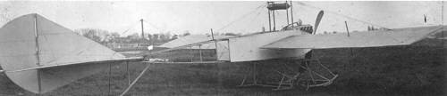
Robert Nau, a French sculptor, had constructed an earlier monoplane in 1909. The photo was taken by French press photographer Louis Branger on May 13th, 1910 on the flying field Port-Aviation at Juvisy-sur-Orge. The Nau Monoplane (1910) was a big machine, with a span of 13 meters and a length of 17 meters, wing area was 24 square meters. The fuselage was half covered. Engine was a 60 hp Renault V-8. After the photo session, which delivered at least two photos, flying was started by Mr. Nau. On May 18th flying ended when the machine with Nau as pilot crashed (it is reported as “falling down”) from a height of 4 meters. Nau was lightly innjured. The machine did not fly after this event.