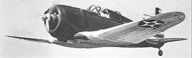
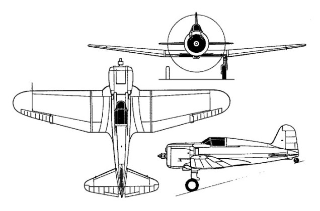
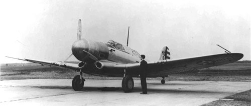
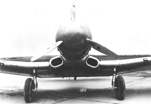
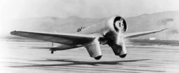
Based on the design of the XFT, the Model 3A was developed as a contender in the US Army’s Materiel Division competition for a successor to the P-26 in service with the USAAC. A low-wing all-metal semi-monocoque monoplane with fully-retractable main undercarriage members and an enclosed cockpit, the Model 3A was powered by a Pratt & Whitney SR-1535-6 Twin Wasp Junior 14-cylinder radial engine rated at 700hp for take-off. It had provision for one 7.62mm and one 12.7mm gun in the fuselage. Completed in July 1935, it was briefly tested at Wright Field where it was found to be somewhat unstable and prone to spinning. Returned to the manufacturer for modification, the Model 3A was under test over the Pacific on 30 July, but failed to return, no trace of the aircraft nor its pilot ever being found. The design of the Model 3A was subsequently sold to Chance Vought Aircraft which further developed it as the V-141.
3A Max take-off weight: 1769 kg / 3900 lb Wingspan: 10.21 m / 33 ft 6 in Length: 6.78 m / 22 ft 3 in Height: 2.77 m / 9 ft 1 in Wing area: 17.37 sq.m / 186.97 sq ft Max. speed: 434 km/h / 270 mph
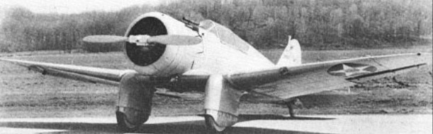
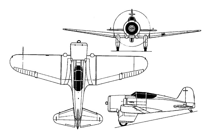
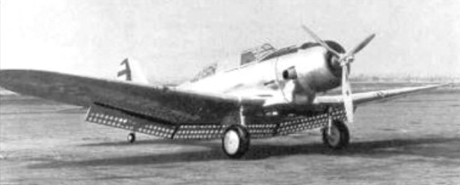
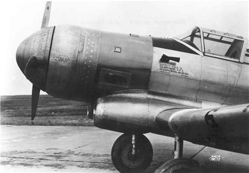
Despite some scepticism concerning the practicability of the monoplane configuration for the shipboard fighter, the US Navy’s BuAer issued a second requirement for such a warplane on 24 January 1933, the first having been issued seven weeks earlier and for which the Boeing Model 273 was designed and built (as the XF7B-1). To meet the later but essentially similar requirement, a contract was let to Northrop for a prototype assigned the designation XFT-1.
A single-seat all-metal cantilever monoplane with split flaps, spatted main undercarriage members and an enclosed cockpit, the XFT-1 was designed by a team led by Ed Heinemann. Powered by a Wright R-1510-26 14-cylinder radial rated at 600hp at sea level and 625hp at 1830m, and carrying two 7.62mm cowl guns, the XFT-1 first flew on 16 January 1934.
The US Navy was critical of its manoeuvrability, its tendency to spin out of certain manoeuvres, its low speed characteristics and its landing speed. During the course of initial tests, an XR-1510-8 engine affording 650hp at 2590m was substituted for the -26, and, in April 1936, the XFT-1 was returned to the manufacturer for more extensive modification. A Pratt & Whitney R-1535-72 Twin Wasp Jnr 14-cylinder radial rated at 700hp for take-off and 650hp at 2285m was installed, this having a long-chord cowling; the vertical tail surfaces were enlarged, and the mainwheel spats were revised.
Redesignated XFT-2, the fighter was now 118kg heavier in empty condition, speed and climb performance were marginally improved, but manoeuvrability and low speed characteristics were worse. It was pronounced unairworthy by the US Navy and crashed on 21 July 1936 while being returned to its manufacturer.
XFT-1 Max take-off weight: 1704 kg / 3757 lb Empty weight: 1120 kg / 2469 lb Wingspan: 9.75 m / 31 ft 12 in Length: 6.43 m / 21 ft 1 in Height: 2.87 m / 9 ft 5 in Wing area: 16.44 sq.m / 176.96 sq ft Max. speed: 378 km/h / 235 mph Range: 1570 km / 976 miles
While the Gamma was being developed, Northrop was working on a nine-seat transport, which was basically a new fuselage married to Gamma wings. Unfortunately for Northrop, the US 1926 Air Commerce Act was amended to prohibit the use of single-engine aircraft for carrying passengers by night, or over rough terrain where emergency landings could not be made. Consequently, airline use for its intended role was nonexistent in the USA, although three had been sold before the new regulation was announced. Eight others were used as executive transports, and one was bought by Swedish AB Aerotransport, which subsequently acquired a second.
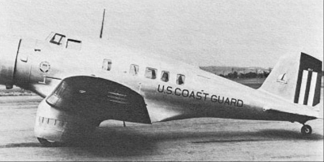
The US Coast Guard operated a Delta under the designation RT-1, as the Secretary of the Treasury’s personal aircraft.
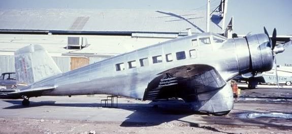
The last Delta was supplied to Canada as a pattern aircraft for assembly in that country by Canadian Vickers, who built 20 of various marks with both wheel and float landing gear. Deltas were flown with various engines, including the 529kW and 548kW Wright SR-1820, 485kW, 492kW and 522kW Pratt & Whitney Hornets.
Northrop used the Gamma transport as the basis of a private-venture design for a light attack bomber, identifying this as the Northrop Gamma 2C which, powered by a 548kW Wright SR-1820F radial engine, was acquired for evaluation by the US Army Air Corps in June 1934 under the designation YA-13. Subsequently re-engined with a 708kW Pratt & Whitney R-1830 Twin Wasp, this aircraft was redesignated XA-16 (Northrop Gamma 2F).
Following tests of the YA-13 and XA-16, Northrop received $2 million contract for 110 attack bombers designated A-17, but because testing of the XA-16 had shown that the aircraft was over-powered, the Gamma 2.F was re-engined with a 559kW Pratt & Whitney R-1535 Twin Wasp Junior, serving as the prototype for the A-17. Following the incorporation of several other modifications, the first of 109 production A-17 aircraft was delivered in December 1935.
A contract was received in the same month for an improved A-17A, introducing retractable tailwheel landing gear and the 615kW Pratt & Whitney R-1535-13 engine. Some 129 were built, initially by Northrop, but in 1937 Douglas acquired the remaining 49% of Northrop Corporation’s stock, and it was the Douglas Company which completed production of these aircraft. Of the total, 93 served with the USAAC for only 18 months, then being returned to Douglas for sale to the UK and France. The Royal Air Force received 60, designating them Nomad Mk I, and all were transferred to the South African Air Force.
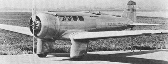
Northrop A-17А
An experiment with the Northrop A-17 aircraft in 1940 consisted in changing the way the air was taken to cool the engine to which the air is fed through special channels at the root of the wing.
Northrop A-17А
These air intakes, even supported by a special suction fan (hot air was emitted through special blinds from above), turned out to be completely inadequate to supply the required air volumes. Ground tests gave normal temperature only at idle speed and without load. Any attempt to increase the amount of power led to a rapid overheating of the engine.
Northrop A-17А
Douglas also built this aircraft for export under the designation Douglas Model 8A, supplying them to Argentina, Iraq, the Netherlands and Norway. In 1939 the first SAAB built 8A-1 was completed (as the B5).
Early in 1940, the Norwegian government ordered 36 8A-5s which not had been delivered before Norway was invaded by the Germans. Completed between October 1940 and January 1941, the aircraft were delivered to a training center in Canada that had been set up for the Norwegian government-in-exile, named “Little Norway” at Toronto Island Airport, Ontario.
The 8A-5 was powered by a 1,200 hp (895 kW) Wright R-1820-87 engine, with four wing mounted 0.30 in machine guns, two 0.50 in machine guns in pods below the wing, a rear-firing flexibly mounted 0.30 in gun, and the ability carry up to 2,000 lb of bombs.
A-33/Model 8A-5
After the loss of two aircraft and a reassessment of the training needs now met by the use of other aircraft, the remaining 34 Model 8A-5Ps were sold to Peru. However, 31 were repossessed by the Army Air Corps at the start of World War II. These aircraft, designated A-33, were used for training, target tug, and utility duties. Serial numbers: 42-13584/13601; 42-109007/109019
A-17A Engine: 1 x Pratt & Whitney R-1535-13 radial, 615kW Max take-off weight: 3421 kg/ 7542 lb Empty weight: 2316 kg / 5106 lb Wingspan: 48 ft 8.5 in Length: 9.65 m / 31 ft 8 in Height: 3.66 m / 12 ft 0 in Wing area: 33.63 sq.m / 361.99 sq ft Max. speed: 354 km/h / 220 mph Ceiling: 5915 m / 19400 ft Range: 1175 km / 730 miles Armament: 5 x 7.62mm machine-guns, 4 x 45kg bombs
Douglas A-33 Powerplant: 1 × Wright GR-1820-G205A Cyclone, 1,200 hp (890 kW) Propeller: 3-bladed variable-pitch propeller Wingspan: 47 ft 9 in (14.55 m) Airfoil: root: NACA 2215; tip: NACA 2209 Wing area: 363 sq ft (33.7 m2) Length: 32 ft 6 in (9.91 m) Height: 9 ft 4 in (2.84 m) Empty weight: 5,510 lb (2,499 kg) Gross weight: 8,600 lb (3,901 kg) Max takeoff weight: 9,200 lb (4,173 kg) Maximum speed: 248 mph (399 km/h, 216 kn) at 15,700 ft (4,800 m) Service ceiling: 29,000 ft (8,800 m) Time to altitude: 10,000 ft (3,000 m) in 5 minutes 48 seconds Guns: 4 × forward-firing .30 cal (7.62mm) 1919 Browning machine guns, 500rpg 2 × forward-firing .50 cal M2 Brownings in gun pods, 200rpg 1 × .30 cal (7.62mm) 1919 Browning machine gun in rear cockpit, 1,000 rounds Bombs: 2,000lb max load Internal: Up to twenty 20 lb (9.1 kg) bombs in internal racks External: Eight hardpoints under the fuselage, four outboard hardpoints can take 500 lb (230 kg) bombs, all eight can carry 100 lb (45 kg) Crew: 2
In January 1932 John Northrop and Donald Douglas formed the Northrop Corporation and the first aircraft from the new corporation was the Northrop Gamma, several of which were built to special order for record-breaking flights and research work. The first two aircraft, a Gamma 2A and a Gamma 2B, were powered respectively by a 585kW Wright and 373kW Pratt & Whitney Wasp radial. Both were delivered at the end of 1932, the first to Texaco who loaned it to Frank Hawks for record-breaking flights.
Gamma NR12265 was built for Lieutenant Commander Frank Hawks of the Texas Company, as a long-range, high speed mail transport in 14/2/33. Named Texaco Sky Chief, it was flown out to the Antarctic via South America to assist with the search for Lincoln Ellsworth when he and pilot Herbert Hollick-Kenyon were declared missing in late 1935. Later sold to “Gar’ Wood and renamed Kinjockety II, it exploded in midair during the 1936 Bendix Trans¬continental Race.
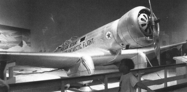
The second, 2B NR12269, being the first to fly after being completed in August 1932. Sold in early 1933 to millionair explorer Lincoln Ellsworth, it was shipped to the Antarctic in late 1933 and test flown on skis by Bernt Balchen before being damaged in an unseasonable ice breakup. The aircraft was back in Dunedin, New Zealand, on 28/1/34 for transshipment on to California for repairs. Returned to the United States after the successful trans polar cap flights between 23/11 and 9/12/35, the Gamma was presented to the Smithsonian on 25/4/36.
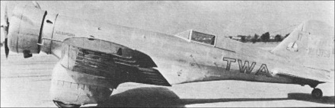
TWA bought three Gamma 2D aircraft with 529kW Wright Cyclone engines as single-seat mailplanes in 1934. The second was later re-engined with a 578kW Wright and was used by Texaco to test oil temperatures and flows before being sold to the US Army Air Corps, which designated it UC-100.
A number of Gammas were delivered to individual customers, including two to the UK, a 2E for the Aeroplane & Armament Experimental Establishment and a Gamma 2L, the last to be built, was used by the Bristol Aeroplane Co. as a test-bed for its Hercules engines.
The Chinese government ordered 24 Gamma 2E aircraft as light bombers, with 529kW Wright engines. They could carry a 726kg bombload and had four 7.62mm forward-firing machine-guns in the wings, and one rearward-firing in the rear cockpit. A further 25 Gamma 2Es were assembled in China from components provided by Northrop.
Engine: Pratt & Whitney Wasp, 500 hp Seats: 2 Range: 2000 miles
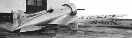
In 1931 Northrop built the prototype of an all-metal low-wing sporting monoplane X/NC12214, the Beta (ATC 2-401), a two-seater with a 119kW Menasco Buccaneer inline engine.
Designed by Don Berlin, a dorsal fairing and canopied cockpit were later added. An advertisement in Dec 1932 Aero Digest quoted a $5,000 sale price.
Stearman-Northrop Beta 3D with dorsal fairing NX12214
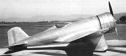
It was converted to single-seat high-speed mailplane configuration in 1933 and fitted with a 300 hp / 224kW Wright Whirlwind radial engine, in which form it became the first aircraft of such power to exceed 200mph / 322km/h. Reported speeds up to 212 mph were reached.
Damaged in a landing accident on 16 January 1933, it was rebuilt by Stearman for planned testing of various wing flaps, but destroyed in a crash on 5 June 1934.
Stearman-Northrop Beta 3D NX12214
Beta 3D Engine: 300hp P&W Wasp Jr Wing span: 32’0 Seats: 1
Northrop’s first aircraft for his new company was known as the Flying Wing but of more immediate consequence was the next design, the Northrop Alpha, an all-metal seven-seat single-engine low-wing monoplane. In 1929 Avion Corporation became the Northrop Aircraft Corporation, a division of United Aircraft and Transport Corporation of which Boeing was also a part.
First flown in 1930, Trans Continental and Western Air Inc, (later to become Trans World Airlines) ordered five Alphas with 313kW Pratt & Whitney Wasp engines and began services on 20 April 1931 from San Francisco to New York, with 13 intermediate stops, the journey taking just over 23 hours.
The Alphas were configured for three passengers and 211kg of mail and cargo, for mail flying was a plum contract at that time, but regularity and reliability was required. To achieve all-weather and night-flying capability, the Alphas had the most modern radio and navigation equipment, and for winter operations became the first commercial type to be fitted with Goodrich rubber de-icer boots on wing “and tail surface leading edges.
Thirteen of the 17 Alphas built saw service with TWA, and three were supplied for evaluation to the US Army Air Corps where, had production orders been given, they would have been designated C-19.
Various configurations carried the designations Alpha 2, Alpha 3, Alpha 4 and Alpha 4-A, and a number of changes were made between individual aircraft as late modifications were made retrospectively to earlier aircraft, including fitting of streamlined ‘trousers’ over the original rather utilitarian landing gear.
The 1931 Alpha 3 was certified under ATC 2-335. The 1931 Alpha 4 (ATC 451) prototype was built at Northrop, the rest at Wichita. Eleven were built, of which 7 were modified from Northrop Alpha 2 and 3. ATC 2-371 was for Alpha 4 NC127W powered by a 420hp Wasp installation.
The 1932 Alpha 4A (ATC 461) was a single-place cargo conversions of Alpha 4. Ten were built.
The last conversion was the Gamma 4-A, an all-cargo aircraft which could carry 567kg; the Gamma 4 and Gamma 4-A had a 336kW Wasp engine and most of the earlier aircraft were similarly retrofitted.
The last surviving Alpha, the third built, served with the US Assistant Secretary of Commerce for Aeronautics, the Ford Motor Company, National Air Transport (part of United Airlines) and TWA. It was re-acquired by the airline in 1975 and superbly restored before being placed in Washington’s Smithsonian Institution National Air and Space Museum.
Alpha 3 Engine: 420hp P&W Wasp Seats: 3
Alpha 4 Engine: 450hp P&W Wasp Wingspan: 43’10” Length: 28’5″ Useful load: 1900 lb Max speed: 177 mph Cruise: 155 mph Stall: 62 mph Range: 650 mi
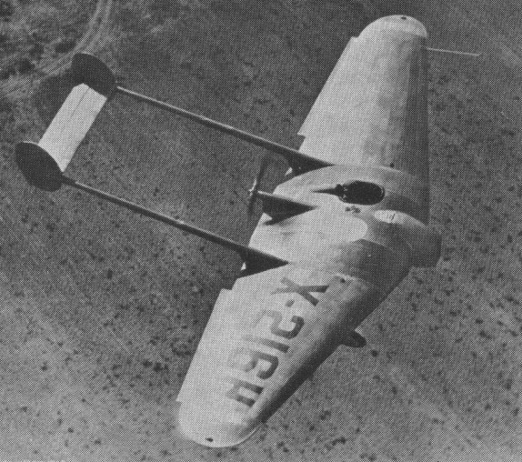
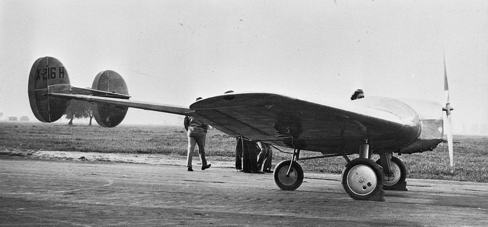
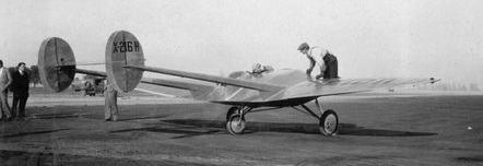
Jack Northrop in 1928 wanted to “do his own thing”, which was to start investigating all wing aircraft, He decided to keep a tail, for the time being. So the Northrop Flying Wing, with experimental registration X 216H, was intended to solve only some of the problems. The wing was a fairly conventional shape, apart from the thick centre section so that the pilot and passenger could sit comfortably inside it on each side of the centre line. The whole structure was a duralumin cellule with multiple spars and a stressed skin. To the rear projected an extremely, light pair of duralumin monocoque tail booms carrying a twin finned tail, the whole assembly weighing less than half as much as a conventional rear fuselage and tail. The main wheels were well forward under the leading edge, and under the trailing edge was a large steerable tailwheel.
The 90 hp / 67kW Menasco Pirate engine was carried just ahead of the leading edge, with cooling air ducted to an outlet near the trailing edge. Northrop was deeply concerned to secure smooth airflow over his flying wings and never again put a propeller in front of one.
The aircraft, built by Northrop’s newly formed Avion Corporation (later the Northrop Aircraft Corporation), initially driving a pusher propeller but modified later to tractor configuration.
Courtesy John Frazer
X 216H flew perfectly well. Reports say it flew well and was 25% faster than anything else in its class. It had conventional controls, and Northrop wanted to explore alternative arrangements and ultimately take the giant step of removing the tail, but he was prevented by financial and business difficulties.
Single seat/side by side two seat single en¬gined flex wing aircraft with weight shift control. Rogallo wing. Pilot suspended below wing in trike unit, using bar to control pitch and yaw/roll by altering relative positions of trike unit and wing. Undercarriage has three wheels in tricycle formation; glass fibre suspension on main wheels. Nosewheel steering independent from yaw control. Aluminium-¬tube trike unit, without pod. Engine mounted below wing driving pusher propeller. Alumi¬nium tubing to US 6061T6 specification, ano¬dized. AN bolts.
It does feature the inclusion of a clutch in its reduction drive, which uses gears rather than the normal belts. Engine is the Lloyd LS400 with electric start, battery and charging system and the trike unit is designed to accommodate either single or side by side dual seat.
Engine: Lloyd LS400 Main wheels diameter overall 20 inch, 51 cm Seats: 1-2
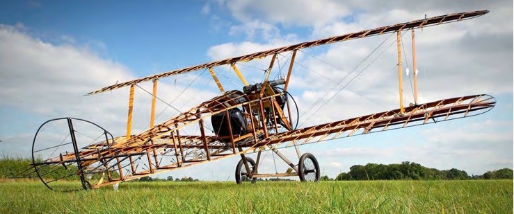
The Northern Aeroplane Workshops F.1 Camel The project was started around 2001, after the construction of the Sopwith Triplane and Bristol M.1C.
Eric Barraclough was the mainstay and inspiration behind the NAW. Having worked for Comper, Heston Aircraft and Auster, he was steeped in aviation. “When the Bristol M1C was coming to completion, we were looking at another project”, recalls Robert Richardson, another NAW lynchpin. “Eric had the idea of building the first Blackburn aircraft, which was an abomination, it really was. None of us were interested in it at all. Then he suddenly turned round and said, ‘I’ve got some Camel drawings in my loft’. He seemed to have forgotten about them.
The first metal was cut when they were still on with the Bristol, in December 1995. That was at the Mirfield workshop, at Butt End Mills, but shortly after that they moved to the workshop at the Skopos Motor Museum in Batley. Once the Bristol was delivered, they started full-time on the Camel.
Eric Barraclough died in November 1997, but the standards he had always desired in NAW’s projects set the tone. Adherence to the original remained to the fore.
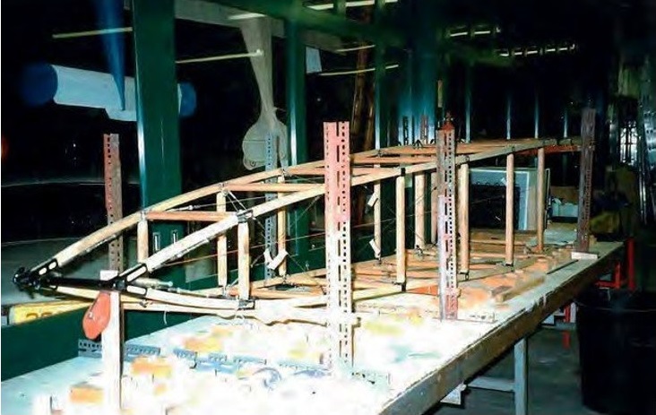
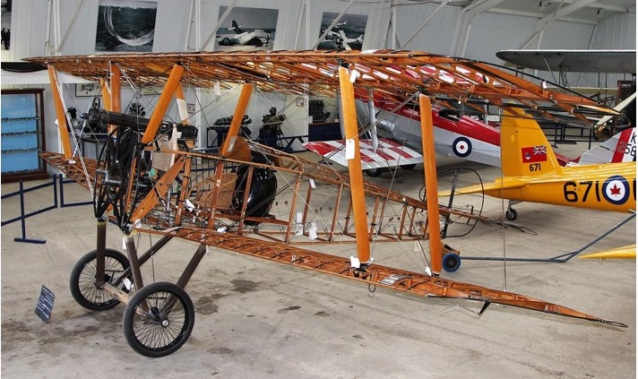
They built the fuselage sides first. All the sub-assemblies like the wings and fuselage were done in jigs.
The fuselage in build at the Northern Aeroplane Workshops’ premises at Alexandra Mills, Batley, in February 1999.
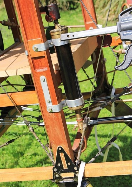
Most of the airframe is spruce, but the longerons are ash. They had woodworkers Chris Lawson, who had his own woodworking company in Skipton. They ordered the streamlined wires from Bruntons, who were making these wires during the First World War.
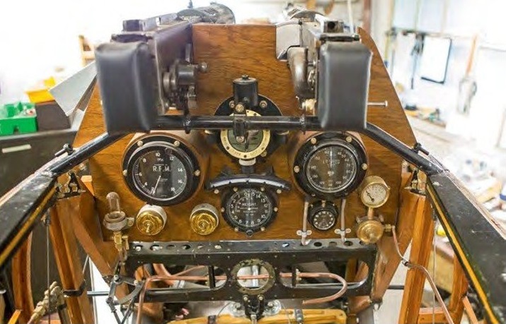
Tube left over from the Triplane for the undercarriage was utilised. It had been specially drawn by a firm called T. I. Reynolds in Sheffield. There were parts coming from all over the place, apart from what they were making in the workshops. The cockpit instruments were sourced by Shuttleworth.
Of the metal fittings made in-house, CAD [computer-aided design] was available, but no one had the expertise to use it, or CNC [computer numerical control] machines and so on. So, it was done the old way. Sopwith would have stamped these fittings out, but they drew them out on a piece of metal, cut them out with a saw, filed them up and bent them as appropriate.
The engine was Shuttleworth’s. All they had was a crankshaft, which was used to set various things up. When they first approached Shuttleworth about the Camel project, one of the things that came to the fore very quickly was a suitable engine. The then chief engineer, Chris Morris, had another Clerget — it’s turned out to be a 9Bf 140hp long-stroke. They thought they could get that airworthy, which they’ve been able to do. It took a lot of work; it needed new pistons, new cylinders, and parts of the tappets as well. Shuttleworth engine specialist Phil Norris is an absolute wizard on rotaries.
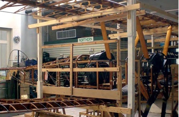
February 2007: in the Batley assembly jig with wings attached, but before the flying and landing wires were fitted.
The first two NAW aircraft were done under CAA auspices, but the Camel was done under the LAA [Light Aircraft Association]. That worked out very well. One of the pilots down at Shuttleworth, Rob Millinship, was the LAA inspector.
Having proved ideal for so long, conditions in the Batley premises deteriorated when they were sold off. Then in 2013 the lease was due for renewal, and Shuttleworth weren’t prepared to renew it. About six NAW members were working on the Camel when it left in August 2013.
At that point, the undercarriage needed final welding. The cables were in, but they weren’t spliced. The systems weren’t in, like the air, fuel and oil systems, so that was all done at Old Warden. That’s probably a good thing, because they’ve got to maintain it. They’ve had to put a small access panel on the port side, which isn’t authentic, but they weren’t able to get to the fuel filter, even going upside-down in the cockpit.
The big things as far as modern standards were concerned were that a four-point harness was put in for the pilot, rather than a lap strap, and obviously the glue. The old casein glue or pot glue that they used in the First World War is not a good idea, so they used Aerodux 500, a very good modern glue.
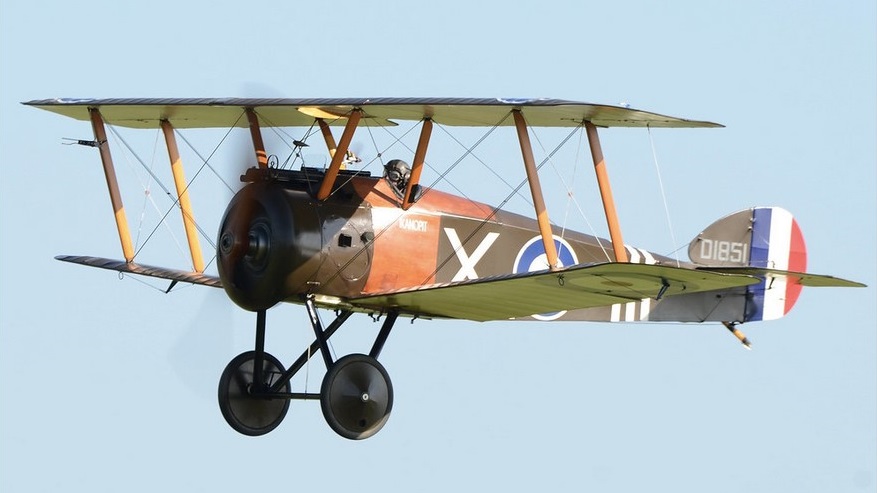
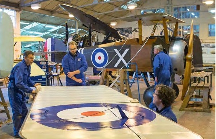
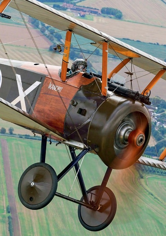
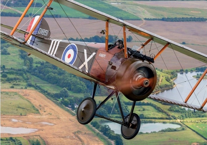
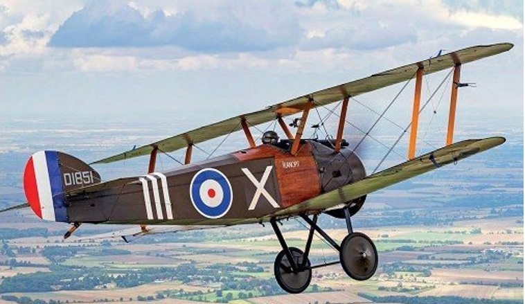
Now overseen by the Shuttleworth chief engineer Jean-Michel Munn, at Old Warden the Camel made visible progress towards completion. The plywood cockpit and side panels, which proved troublesome, were completed before the airframe was taken down to be covered, using synthetic materials rather than linen. The chosen colour scheme was that of a Ruston Proctor-built example operated by No 70 Squadron, Royal Flying Corps, the first front-line unit to receive the type. It carries the serial D1851 and is named Ikanopit (‘I can hop it’).
Members of the Shuttleworth engineering team refitting the wings in February 2015. From left to right in the foreground are Andy Preslent, Gareth Rutt and Rory Cook, while Phil Norris stands by the aircraft’s nose.
Engine runs began in August 2016, leading up to the following May’s successful maiden flight.
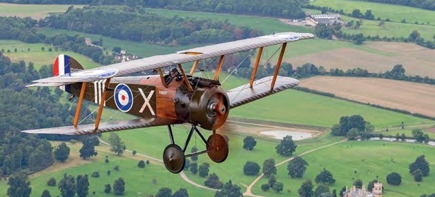
Roger ‘Dodge’ Bailey flies the reproduction Camel near Old Warden August 2017.
When ‘Dodge’ Bailey, the Shuttleworth Collection’s chief pilot, took Sopwith F1 Camel reproduction ‘D1851’/ G BZSC into the air for the first time at Old Warden on 18 May 2017, it brought one of the historic aviation scene’s most compelling stories to a close. The West Yorkshire-based Northern Aeroplane Workshops, established back in 1973, shut up shop when the Camel was moved to Old Warden for completion during the summer of 2013, but the machine’s maiden flight marked the very end of the group’s final project.
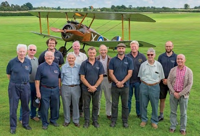
Robert Richardson describes the Camel project as “a great marriage between NAW and Shuttleworth”, members of whose teams gathered for this photograph. Back row, left to right: David Barraclough (Eric Barraclough’s son), Rory Cook, Robert Richardson, ‘Dodge’ Bailey, Phil Norris and Gareth Rutt. Front row, left to right: John Thompson, Geoff Kilner, Rod Elliott, Andy Preslent, Jean-Michel Munn, Horace Darlington and Ian Whitwan.
In preparation for that, ‘Dodge’ Bailey did a great amount of homework. He used three-view diagrams of different Sopwith types, all to the same scale, on acetate sheets that could be laid over one another to afford the most direct comparison: they depict the Camel, 1½ Strutter, Pup, Triplane and Snipe. Amongst other things, they showed that the Camel’s tailplane is about 60 per cent of the size of the Pup’s, and that the fin is smaller too. The tail arm is longer on the Triplane, making the tail more effective. They both preceded the Camel; its Snipe successor, meanwhile, saw the tail going back to the sizes of the previous aeroplanes, and the fin and rudder made significantly larger. “That tells you a lot about what the aeroplane’s probably going to be like”, says ‘Dodge’. “A very simple technique, but quite illuminating.” Then there were period scientific and technical papers to read, drawings made by the Germans of a captured Camel and reproduced in Flugsport to examine, and numerous references to study. In his weighty tome Flying Qualities and Flight-Testing of the Aeroplane, former CAA test pilot Darrol Stinton described flighttesting a Clerget-engined Camel. A May 1968 issue of Flight International includes a piece by six-victory Royal Naval Air Service pilot Capt Ronald Sykes on flying a Bentley BR1-powered example. Best of all, ‘Dodge’ feels, are the writings of Wg Cdr Norman Macmillan, who was operational on RFC/RAF Camels on the Western Front and in Italy, and subsequently flew the type while instructing at a fighter school back home in the UK. Apart from several books, Macmillan wrote an article on his Camel experiences that, some years after his death, appeared in the October 1984 Aeroplane Monthly; it was called ‘A Fierce Little Beast’. In that feature, says ‘Dodge’, “There’s some really good advice, and counterintuitive advice: for example, to start the take-off with the stick on the carburettor intake tubes. Because the Camel cockpit is set more forward, the carburettor is closer to the pilot than in earlier types. To start the takeoff with the stick on the intake tubes means the stick is fully forward. It’s pretty unusual to do that. On most taildraggers you would start with the stick back, and some you would start with the stick kind of neutral. What I had to think when I read that was, ‘why on earth is he telling ab initio students to do that?’ “This is one of the bits that I don’t understand about the thinking at Sopwith at the time. If we overlay the Camel and the Pup in side view, you can see that the cockpit has moved from the trailing edge to under the centre-section, so the distance from the cockpit to the engine has changed; they moved the pilot forward. In the Pup, the area under the guns, pretty much where the centre of gravity is, is where the fuel tank is. Any aircraft designer will tell you to put the fuel tank on the centre of gravity; then, as the fuel burns, it doesn’t change the CG. Whatever made them move the cockpit forward means that the fuel tank can no longer go there so it goes behind the cockpit, well aft of the CG. When the fuel tank is full of fuel, the CG is a long way aft. That’s a clue to why the guy is saying, ‘stick fully forward’. It means that when the aeroplane is in flight it is not in trim.
Airborne Old Warden Park.
It was one of its Camels, B7270, that was officially credited with the shooting-down of Manfred von Richthofen before evidence came to light that the ‘Red Baron’ probably fell victim to ground fire. Clayton & Shuttleworth employees were given a speciallyprinted leaflet commemorating their product’s feat. “Now, you have to be a bit careful about the term ‘in trim’ because it means different things to different people. To pilots, ‘in trim’ means, ‘I have trimmed the aeroplane; I can take my hands off and it flies straight, it doesn’t pitch up or pitch down’. That is, if you like, ‘controls-free in-trim’… To a flight dynamicist, ‘in-trim’ means that the sum of the moments is zero; in other words, that the aeroplane isn’t pitching, but the pilot might be holding a huge control deflection and/or force to hold it in that condition. If he lets go of the stick it wouldn’t be in trim at all; it would pitch. The Camel is like that. In order to stop the aeroplane pitching you need a relatively large stick force. What the aeroplane wants to do when you’re taking off with a full fuel tank is pitch up. “Imagine that a student used to taking off in an aeroplane with the stick back takes off in a Camel — it’s got twice as much power, maybe three times as much, as he’s used to. It’s very lightly wing-loaded and it’ll be airborne in no time. If the stick is back and the aeroplane is ‘out of trim’ it will just pitch up as it leaves the ground, and he will just stall and crash straight away. “By putting the stick forward Macmillan knows there is no chance of the pilot putting the aeroplane on its nose, because the CG is so far aft. The first thing that happens is that he’ll see the tail coming up once the take-off starts, and then he can adjust the stick position. If he’s late, if he holds the stick back and doesn’t get it forward early enough, the aeroplane’s going to pitch up. It’s all about anticipating the reaction of the aeroplane when it gets airborne. You don’t actually leave the ground with the stick fully forward; like I say, as soon as the aeroplane’s rolling and the tail comes up you can move the stick to hold the normal take-off attitude for a taildragger. When you get airborne you’re pushing on the stick all the time to stop the aeroplane pitching up. “I am told that if you run the aeroplane right out of fuel, like they would have done, by the time it’s empty the CG has moved pretty much on to the forward limit, and now you’re pulling all the time to the point where it became quite difficult to do three-point landings. The pull force needed to get to that position was quite a lot, and you might run out of elevator before achieving the three-point attitude. We never fly it that short of fuel, so we’ve not been there. “So, the Camel is, if you like, ‘out of trim’ with any sort of fuel in it at all, and under that ‘out-of-trim-ness’ it is also unstable. You’re dealing with an aeroplane that requires a force to maintain its attitude, but the force changes after a disturbance will likely be unpredictable. “One of the mitigations we came up with was to only use a half-tank of fuel… the other thing was that, because [this Clerget] is a really nice engine, to throttle up relatively steadily. That made the take-off a little bit more manageable. I really anticipated the aeroplane to be unpleasant in pitch, because every bit of evidence suggested it would be, and it didn’t disappoint in that regard. “I also expected turns, particularly to the right, to be compromised by the gyroscopic precession. I found on first acquaintance that even left turns were pretty unusual. These were climbing turns, because I was climbing out. I continued to climb until 3,000ft or so and then throttled back, and as soon as the power came back below about 1,000rpm the aeroplane started to get a bit more pleasant — or less unpleasant. The pitch deficiency is at its worst at high power, and pretty much has gone away by the time you’re gliding, so you don’t really notice it when you’re coming in to land. One of the things you tuck away in your head is, ‘if it all gets too much, throttle back’, which might be counter-intuitive to some people. “What was more of a surprise was how directionally sensitive the aeroplane was. There are very few aeroplanes that I have flown that behave like this; I think the Comper Swift is similar, but not as bad. Most aeroplanes you want to fly in balance, so you put the slip indicator in the centre — using the rudder, normally. Once you have put the rudder in that place, and your feet hold the rudder in that place, things won’t change unless you change the power or the speed or aileron. That’s not the case in the Camel. Having put the aeroplane in balance it doesn’t stay that way. It’s the directional equivalent of the pitch handling characteristics, in the sense that it will diverge from that condition you thought you had sorted out, and you have to put it right again. Darrol Stinton refers to that as, ‘there is no stability, it’s all control’. You not only have to control the pitch, which you were kind of expecting, but the yaw as well… ”I expected turns, particularly to the right, to be compromised by the gyroscopic precession. I found on first acquaintance that even left turns were pretty unusual”
Sopwith F1 Camel reproduction ‘D1851’/G-BZSC Shuttleworth Collection
“What it boils down to is that you have to be actively in the control loop all the time. Reputedly the only time a Camel will fly hands-off in-trim is when it’s inverted. I think if you were to fly it enough you would get to love it, and in one of Macmillan’s books he reckons it’s maybe 15 hours on the Camel and then you’ve adapted to the aeroplane. I haven’t got 15 hours on the Camel; I’ve probably got three, so what I’ve been relating are first impressions of a strange aeroplane.” In combat, flown by someone with the requisite experience, ‘Dodge’ says the Camel, “could be manoeuvred in a very unpredictable way, so it would be a very difficult target. Equally, they could get on the tail of a more predictable aeroplane, which couldn’t manoeuvre anywhere near as aggressively as the Camel. What the Camel couldn’t do was go fast; it couldn’t run away or chase, it just had to fight, and it did that very well in a tight dogfight. “One of the things you notice when you’re flying tight turns is that the gyroscopics of the engine start to dominate things. If the aeroplane pitches up, the gyroscopic precession causes it to yaw to the right. Whenever you’re turning steeply, as far as the aeroplane is concerned it is pitching up to go round the turn. If you’re making a left turn, the aeroplane is pitching up so it’ll yaw right. To stop it yawing right you need to apply left rudder. When you enter the turn you use some left rudder and left stick; then, having got the bank on, the nose is pitching up and so that left rudder needs to stay on — and even a bit more. In a left turn it does not feel particularly odd. Now, in a right turn, you might need a little bit of right rudder as you start to roll in to balance, but as soon as a pitch rate appears that right rudder is no longer appropriate. You need left rudder now. In a steep right turn, if you don’t apply left rudder the nose will yaw down towards the ground. The tightness of the right turn is limited by how much left rudder you can get on. You can end up in a tight right turn, going round apparently on a sixpence, probably only just getting rid of the push force — so you’re not pulling particularly, you’re just relaxing the push force — with nearly full left rudder on, and the aeroplane is perfectly in balance. That does feel odd”. On other Sopwiths, he continues, “the gyroscopics are there, but they are less intrusive because the tail volumes are greater.” Power is, of course, a factor. “This Camel has the 140hp, long-stroke Clerget engine. Somewhere in the documentation for that engine it says you must not use full throttle at sea level. Effectively it gives you a bit of enhanced performance at altitude that you’re not allowed to use low down. Full rpm would be 1,200- 1,250, and at that setting, with nearly full power on, the aeroplane is at its most cantankerous. But for what we need to do, we don’t ever need to apply that amount of power. What I’ve found is that if we take off with maybe 1,100rpm and get the climb to display height out of the way, as soon as you’re high enough come back to 1,000rpm, and then you’ve got a less challenging aeroplane.” It had been hoped to display the Camel at both of the last two Shuttleworth shows of 2017, but conditions were too windy. With all the usual provisos, it should make its public flying debut at a very appropriate occasion: the 2018 Season Premiere event on Sunday 6 May, marking the RAF’s centenary. There the fruits of so many labours will hopefully be airborne for all to see, and the exploits of one of the greatest British fighters recalled. When Sir Thomas Sopwith saw the Northern Aeroplane Workshops-built reproduction Triplane, he thought it so good that he famously declared it a ‘late-production’ example. Were the great man still alive, he would surely consider just the same to be true of this Camel.
The Camel demands notably careful handling in many areas of its flight envelope, but the rewards are there for the seasoned pilot. ”You have to be in the control loop all the time. Reputedly the only time a Camel will fly hands-off in trim is when it’s inverted”