Stemme S.10 / TG-11A

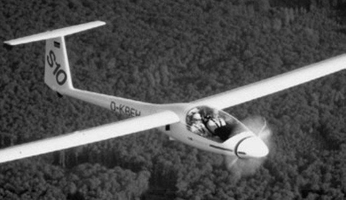
A two seat, side-by-side, motor-glider designed by Reiner Stemme, first flown in 1986, and first produced in 1990 at the Stemme factory at Strausberg Airfield, east of Berlin. The fuselage has a central steel tube frame, which forms the attachments for the wings, undercarriage and fixed internal powerplant. The carbon fibre rear fuselage bolts onto this frame, and the cockpit sec¬tion, which is a Kevlar lined carbon fibre shell, fits on the front. It has an electrically retractable undercarriage; not the conven¬tional glider mono wheel, but the more con¬ventional powered aircraft variety (although the track is quite narrow at 1.15 m). The engine is mounted behind the cockpit with a carbon shaft running through a Kevlar tunnel to a folding prop located behind a large retracting nose cone.

There are three basic varia¬tions of the Stemme, the S10, the S10V and the S10VT. The S10 has a four cylinder 93 hp Limbach four-stroke engine powering a fixed-pitch propeller. This combination gives a cruise speed of 90 knots. The S10V uses the same engine but with a variable-pitch propeller, giving a higher cruise speed of 121 knots.

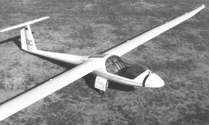
The S10VT utilises a 115 hp turbocharged Rotax 914 engine, which gives a cruise speed of 140 knots at 10,000 ft. All variations a have a 23 m wingspan and can achieve a glide ratio of 50:1 while accommodating a crew of two. The three piece, 23 metre span, folding wings, contain two 45 litre fuel tanks.

Stemme S-10VTX

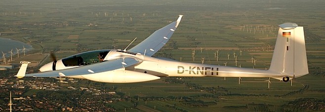
The S 10 VT engine, a 115 horsepower Rotax 914 Turbo (thus the “T” in the designation) with water cooled heads and a dual ignition system, is located in the lower fuselage be¬hind the cockpit. A centrifugal clutch turns a carbon fibre driveshaft, which is encased in a Kevlar tunnel and runs through the cen¬tral console to a reduction gearbox (0.9: 1) mounted behind the propeller in the nose section. The variable pitch (the “V” in the designation) folding propeller blades extend au¬tomatically by centrifugal force when the engine is started, with the nose cone mov¬ing forward and out of the way. When the engine is stopped, the blades fold inwards by a spring system and the nose cone is re¬tracted (which takes about six seconds) and the machine becomes a glider. The two-seater has carbon-fiber wings and solar panels for 30W of electrical power once airborne.

No. Built: 60

The U.S. Air Force Academy operates 2 S 10’s as the TG-11 A model (S 10VT), 94-1400 and 94-1500 also as civil N94FT and N94FW.

S10
Engine: 69 kW/ 93 bhp Limbach L2400 EB1. D
Wing span: 23m / 75.46 ft
Wing area: 18.74sq.m / 201.7sq.ft
Aspect ratio: 28.22
Airfoil: HQ-41
Empty Weight: 635kg / 1400lb
Payload: 215kg / 474lb
Gross Weight: 850kg / 1874lb
Wing Load: 45.39kg/sq.m / 9.29lb/sq.ft
Cruise: 90 kts
L/DMax: 51
MinSink: 0.56 m/s / 1.83 fps / 1.08 kt
Structure: GFRP/ CFRP/ Kevlar/ Steel tube
Seats: 2

S10V
Engine: Limbach, 93 hp
Prop: variable pitch
Wing span: 23m / 75.46 ft
Wing area: 18.74sq.m / 201.7sq.ft
Aspect ratio: 28.22
Airfoil: HQ-41
Cruise: 121 kts

S10
Engine: Rotax 914, 115 hp
Wing span: 23m / 75.46 ft
Wing area: 18.74sq.m / 201.7sq.ft
Aspect ratio: 28.22
Airfoil: HQ-41
Cruise: 140 kts

Steen Steenship

LaMar Steen’s first airplane was a two-place, low-wing design named the Steenship. The Steenship has wooden wings, a tube-and-fabric fuselage, and originally sported a many-coat nitrate dope covering job. The modified O-290-G engine produced 140hp and gave the plane a very respectable cruise speed of 165 mph. In addition, it was stressed for aerobatics (+/- 9 G). Construction took 3-1/2 years and cost $3,800.

It first flew in July 1966 as N881LS. No plans were ever made available for the Steenship, and no original blueprints or construction drawings exist today.

The May 1989 issue of Sport Aviation had an article about Bob Leonard’s restoration of the plane in Healdsburg, CA. In mid-2002, Burt Nichols in Arkansas purchased it (still retaining the original registration number N881LS) and flew it regularly. After 200 hours in the first 9 months he decided to upgrade the original Lycoming O-290 to a Lycoming O-320. As of July 2003, it was very close to first flight with the new engine.

In late Jan. 2005, it was in the process of a rebuild.

Engine: 140hp Lycoming O-290G
Cruise: 145 mph
Stall: 60 mph
Load factor: 9G±
Seats: 2

Steen Firebolt

A Firebolt was Grand Champion at Oshkosh 1988.

Top speed: 214 mph
Cruise: 185 mph
Stall: 61 mph
Range: 550 nm
Rate of climb: 4000 fpm
Takeoff dist: 400 ft
Landing dist: 850 ft
Service ceiling: 18,000 ft
Engine: Lycoming IO-540
HP range: 180-340
Fuel capacity: 39 USG
Empty weight: 1354 lb
Gross weight: 2000 lb
Height: 7.6 ft
Length: 21 ft
Wing span: 24 ft
Wing area: 150 sq.ft
Seats: 2
Landing gear: tailwheel

Steen Skybolt

The Skybolt is a two-seat aerobatic biplane designed by Lamar Steen, an aerospace teacher in Denver. It first flew in October 1970 and received the EAA award for “Best School Project.” The Skybolt is stressed to + 12G’s and -10G’s. The wings are built around two spruce spars and are fabric covered, with four ailerons. The fuselage is a fabric-covered welded steel-tube structure. The aircraft can be fitted with engines ranging in size from 125 to 260 hp.

Gallery

Engine: 180-hp Lycoming
Gross Wt: 1680 lb
Empty Wt: 1080 lb
Fuel capacity: 30-40 USG
Wingspan: 24 ft
Length: 19 ft
Wing area: 155 sq.ft
Top speed: 145 mph
Cruise: 130 mph
Stall mph: 50
Climb rate: 2500 fpm
Ceiling: 18,000 ft
Takeoff run: 400 ft
Range: 450 sm
Seats: 2

Engine: Lycoming IO-360-A1A, 200 hp
Vne: 170 kts.
Fuel cap: 110 lt + aux 37.85 lt.

Engine: Lycoming IO-540-D4A5, 260 hp
Speed max: 180 mph
Cruise: 160 mph
Range: 450 sm
Stall: 60 mph
ROC: 3500 fpm
Take-off dist: 300 ft
Landing dist: 800 ft
Service ceiling: 18,500 ft
HP range: 125-260
Fuel cap: 38 USG
Weight empty: 1250 lbs
Gross: 1800 lbs
Height: 7.2 ft
Length: 19 ft
Wing span: 24 ft
Wing area: 152.7 sq.ft
Seats: 2
Landing gear: tail wheel

Steel Breeze Mini Breeze

In 2005 ASAP introduced another member of the PPC family, the Steel Breeze and Mini Breeze conforming to the FAR 103 regulations.

The Standard 103 Mini Breeze airframe is a powder coated 1 ½ inch 4130 .049 chrome molly aircraft quality TIG welded frame cage, with a black anodized 6061T6 1 ¼ inch Aluminum Prop guard. The seat fuel cell holds 12 US gal, (limited to 5 gal for USA 103) with a deluxe black seat covers and 4 Point Safety harness for both seats.

Fitted with a GSC fixed pitch propeller (std prop is a 2 blade 64″), or a ground adjustable is optional.
Features are, 6” spun AL rim with CNC machined hub and high speed bearing (13” OD), Butterfly Steering wheel with u-joint controls, Dyno-focal motor mount, Stainless Steel cable and clamp with 4 point riser attach system, Mustang 380 Sq. Ft. high performance canopy with canopy bag and line socks included, Long handle Throttle Quadrant, Foot bars canopy steering system, and Unique bungee control shock dampening system. Used on many certified aircraft.

Width Standard wheels: 72 in
Overall width at prop guard: 72 in
Length: 101 in
Height top of prop guard Standard wheels: 85 in
Airframe weight, w/Parachute Wing: 140 – 145 lbs

Steel Breeze Powered Parachutes Steel Breeze

In 2005 ASAP introduced the two place Steel Breeze powered parachute and Mini Breeze conforming to the FAR 103 regulations.

The main fuselage of the Steel Breeze airframe is constructed of 1.5 inch diameter chromolly steel fabricated and aircraft welded. Tabs are welded onto the airframe to attach the anodized aluminum components used to complete the PPC structure.

The Steel Breeze has a roll bar frame, frontal bars, wide center of gravity attach points and true seat separation. The 4 point riser attach system gives this aircraft a solid platform and with directional input that stays solid in the turn with no twisting or bobbing. The higher than center thrust line lateral attach gives a comfortable rate of climb. This also provides smoother throttle transition during landing as the aircraft has less tendency to oscillate with throttle setting changes.

Rear Seat tank, comfortable and lots of leg room. Front Pilot seat is a full highback seat in a comfortable seating position. Both seats come standard with 4 point safety harness. Full roll cage protection and frontal bars are standard. Full action bungee suspension is simple, works well and is very easily maintained. A Dyno-focal motor mount keeps engine vibration to a minimum. Cable system risers and stainless steel attach points make the strength to handle in excess of 5 G’s in load testing.

The Steel Breeze Powered Parachute may be the first new PPC to enter the market with the SPORT PILOT Manufacturers standards already in place. Steel Breeze is in compliance with Sport Pilot LSA.

The Steel Breeze airframe allows a variety of engine options that will fit the airframe. The basic airframe was available less the engine and canopy. The Steel Breeze can come ready to fly or ready to assemble. Factory built Steel Breeze is ready to fly, just uncrate it, put the wheels on, put gas in and fly. Factory built Steel Breeze is completely set up and test flown before it is packaged. Freight cost is higher due to size of finished package.

The welded main frame makes the Steel Breeze Kit assembly simple and fool proof. Kit comes with everything you need to complete the aircraft.

Standard Steel Breeze Airframe consists of:
Main airframe (Powder coated 1 ½ inch chrome molly aircraft quality TIG welded frame cage), Black anodized 6061T6 1 ¼ inch Aluminum Prop guard.
Dual deluxe seating, rear seat fuel cell 14 US gal., deluxe black seat covers.
4 Point Safety harness for both seats.
64 inch GSC Tech 3 propeller ground adjustable
8” Azusa Aluminum Mag Wheels
Butterfly Steering wheel with u-joint controls.
Dyno-focal motor mount
Stainless Steel cable and clamp with 4 point riser attach system
Mustang 500 sq.ft canopy with canopy bag and line socks included.
Long handle Throttle Quadrant
Foot bars canopy steering system
Unique bungee control shock dampening system. Used on many certified aircraft.

Construction Materials:
Aircraft quality TIG welded frame 1 ½” 4130 .063 Chrome Molly
1 ¼” 6061 T6 Aluminum Aircraft Grade
Quality AN aircraft hardware.
Stainless Steel bracketing.

Width at main gear wheels Standard wheels: 70 inches
Width at main gear wheels Jumbo wheels: 74 inches
Overall width at prop guard : 76 inches
Length: 123 inches
Height top of prop guard Standard wheels: 83 inches
Height top of prop guard Jumbo wheels: 85 inches

Airframe only weight, including Parachute Wing and Propeller less engine: 227 lbs

Steel Breeze airframe with:
Rotax 503 DCDI, B-Box with Pull Start: 323 lbs
Rotax 503 DCDI, B-Box w/Electric Start & Mag End: 343 lbs
Rotax 503 DCDI, C-Box (dampener) w/ Pull Start: 331 lbs
Rotax 503 DCDI, E-Box w/ Electric Start: 347 lbs
Rotax 582 Liquid cooled B-Box w/Pull Start : 342 lbs
Rotax 582 Liquid cooled B-Box w/Electric Start and Mag End: 361 lbs
Rotax 582 Liquid cooled E-Box w/Electric Start: 363 lbs
Hirth 3503 Liquid cooled with gear box and Electric Start: 350 lbs
HKS 700E 4 stroke with Electric Start: 376 lbs

Maximum Gross Weights:
These posted weights are based on Parachute Wing size and type.
Mustang S-500 (Rectangular): 850 lbs
Mustang S-550 (Rectangular): 950 lbs
Thunderbolt E-340 (Elliptical): 900 lbs

Glide Ratio: Between 4 to 1 up to 6 to 1.
Rate of Climb: Between 400 to 800 feet per minute.
Take off Roll: 50 to 300 feet
Landing Roll: 50 to 100 feet.
Cruise Airspeed: 25 to 35 mph. (Elliptical wings 31-45 mph)

Stebbins-Geynet Tri-Bi-plane / Model A / Model B

Airplane built by the Stebbins-Geynet Aeroplane Company of Norwich, Connecticut (William H. Stebbins of the USA and Louis Geynet of France), possibly the model A of 1909, which was equipped with a Cameron 25-30 hp four-cylinder, air-cooled engine. As a tri-bi-plane it had a detachable middle wing, which once removed converted the machine from a triplane into a biplane. Positive control was secured by use of the Stebbins-Geynet “auto-control” system. A pull or push movement operated the elevating rudders, while the balancing was done by means of side movements or slight turns. The rear vertical rudder was manipulated by means of a foot lever. It featured a single-place, open cockpit.

The Model B followed in 1910, same as the Model A, but with a seven-cylinder Holmes-modified Gnôme rotary, and 6sqft rudder instead of 10sqft.

Model A
Engine: 35-40hp Cameron pusher
Wingspan: 24’0″
Seats: 1

Model B
Engine: Gnôme
Wingspan: 24’0″
Seats: 1

Aerial Aircraft Model A / Model B / Model C / Steaman Aircraft Company B-2

Stearman B-2

The Aerial Model B first appeared in 1941.

In February 1942 Aerial Aircraft Inc changed its name to Steaman Aircraft Company (not related to the Stearman Aircraft Company).

Production of the Model B resumed in 1944 when three were built.

The Models A, B, and C differed with the engines.

Aerial Model B
Engine: 65 hp Lycoming O-145-B2
Seats: 2

Aerial Model B
Engine: 75 hp Continental A75
Seats: 2

Aerial Model B
Engine: 80 hp Franklin 4AC-176
Seats: 2

Stearman B-2
Engine: 75 hp Continental A75
Wingspan: 30 ft
Length: 20 ft 2.5 in
Empty weight: 680 lb
Loaded weight: 1200 lb
Max speed: 125 mph
Cruise: 110 mph
ROC: 930 fpm
Range: 430 mi
Seats: 2