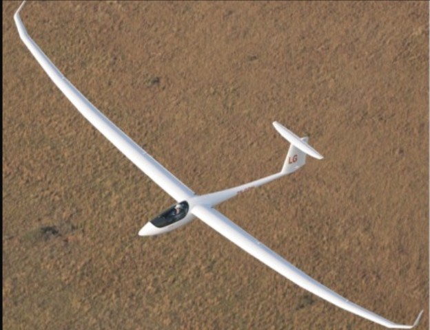
The JS1 Revelation is a high-performance FAI 18-metre Class sailplane, fully-equipped in its baseline standard. An optional jet sustainer system is available. With the introduction of the JS1C variant, there was also the additional option of 21-metre wingtips for an ‘agile’ Open Class sailplane.
The design process of the JS1 Revelation started with development of the main wing aerofoil. After wind tunnel tests together with new technology and research on techniques that might help climbing performance, then after making hundreds of iterations, they ended up with the T12 aerofoil.
To optimize climbing in turbulent thermals the T12 does not have the typical flat top Cl-Alpha curve at high lift coefficients.
T12 characteristics:
Maximum thickness/chord ratio 12.7%
14% camber changing flap
Low drag with extensive regions of laminar flow
Laminar to turbulent transition on the lower surface occurs at 93% where artificial transition is applied for negative flap settings
Transition on the upper surface occurs at approximately 65% for a 0° flap setting and 2° angle of attack
The top surface is smooth at 13.5° with almost 70% laminar flow
Although aerodynamically optimised, there are structural challenges using such a thin aerofoil. At the time the T12 aerofoil was the thinnest main aerofoil used on modern sailplanes.
The aerodynamic design of the wing root reduces separation problems at the trailing edge and optimised overall drag. Six different aerofoils are used in the wing for maximizing the performance of the glider. All are derived from the main T12 aerofoil, optimised at each spanwise station for the specific chord length and Reynolds number. The wingtip aerofoil is designed with an ample lift reserve to help handling characteristics and avoid any tendency for wing drop.
The optimum wing planform has an elliptical lift distribution for minimum induced drag at low speeds, and a small wing area for reduced profile drag at high speed. The wings of the JS1 Revelation have six tapered polyhedral sections along the wing span, with aerofoils based on the T12 aerofoil optimised at each spanwise position for the specific chord length and Reynolds number. The polyhedral also contributes to the handling qualities.
The winglets for the JS1 Revelation were specifically tailored for the wing shape and tip airfoil. For all operational angles of attack, the load on the tip region was kept within limits of the maximum airfoil lift coefficient, for safe handling characteristics. Due to the polyhedral wing configuration of the JS1 Revelation, the last wing panel is already at an angle of 24 degrees which increase the angle between the winglet and wing. This reduces the detrimental 3D flow effects at the junction corner due to super positioning of adverse pressure gradients which causes separation.
Conventional structures (such as the controls and landing gear) were designed using traditional calculation methods, with hand calculations for simple geometries and laminate analysis for simple composite structures. The more complex structures were designed using FEM analysis techniques.
A combination of glass-fibre, aramid (Kevlar) and carbon-fibre is used in the load bearing structure of the JS1 Revelation. The very thin wing section (12.7%) posed a challenge for the designers, especially in the wing root area where the maximum thickness is only 100mm.
All structural design was according to the certification standards set in CS-22 and with a general safety factor of 1.725.
Standard features include a multi wingspan, including 18m wingtips with provision for 21m wingtips, a nose release hook and provision for a belly hook enclosed by main wheel doors, a fixed pneumatic tail wheel (brass or Vesconite), a multi-probe (pilot, static pressure and Total Energy), and two recessed battery boxes in baggage compartment and battery compartment in vertical stabiliser
The cockpit has a gooseneck dynamic microphone attached to canopy frame, tick mounted PTT switch and twin speakers for radio and navigation computer, a radio antenna in vertical stabiliser and provision for Dolba transponder antenna installation inside vertical stabiliser.
Boundary layer control is with blowholes and soft tripping turbulators. Integrated main water ballast tanks (approximately 2 x 90 litres) are in the main wings with automatic coupling and maintenance-free valves. An integrated non-dumpable C.G. water tank is in the vertical stabiliser (for optimum C.G. when compensating for pilot and equipment)
Triple-panel upper-surface airbrakes are fitted and the retractable undercarriage has elastomeric shock absorbers. Hydraulic disc brake are activated by full aft travel of airbrake handle.
Jonker Sailplanes selected the M&D Flugzeugbau TJ42 jet turbine engine as an option.
Finite Element Modeling (FEM) allows for the whole structure to be represented as a wire frame of cells or elements called “the mesh”. Loads can then be applied to the mesh and the stresses calculated at each point. The result is a colorful representation of the stress condition throughout the structure. This shows exactly where the structure needs strengthening and where weight can be saved. The figure below shows the stress condition in the front and aft fuselage due to a load on the tail, and a high-g pullout maneuver.
In March 2010 the JS1 Revelation gained its official certification by the South African Civil Aviation Authorities (SACAA). With SACAA Type Certification to CS-22 and with an SACAA ICAO- compliant Certificate of Airworthiness the JS1 Revelation should be able to be flown without restriction in any ICAO-signatory country.
However JS recognises that EASA (and its predecessor, JAA, and the German LBA) are widely acknowledged as the experts in glider certification and that it is important to gain EASA Type Certification (TC) or Type Validation (TV) of the JS1 Revelation, both for market confidence and to enable local registration of the JS1 in Europe. Local registration would allow local maintenance procedures to be applied.
JS and SACAA have been in discussion on how to best proceed with EASA TC/TV. A full EASA TC exercise would require repeating all ground and flight tests with EASA witnesses and re-submitting every report and analysis for EASA scrutiny. This would be unnecessarily time-consuming, expensive and inefficient as it would completely ignore everything done for the SACAA Type Certification. This would be inconsistent with the advice provided by EASA to SACAA and JS, namely to gain local South African Type Certification before presenting this to EASA.
An EASA Type Validation exercise allows EASA to take advantage of the tests, reports and analyses already accepted by SACAA – while at the same time reserving the right to require extra information for any areas of special interest or concern. However in order to use a Validation process (rather than a full Certification process) it is necessary to establish a Working Arrangement between SACAA and EASA – simply a legal framework to allow EASA to accept SACAA findings on the basis that SACAA have followed a robust and rigorous process.
For the SACAA, establishing a Working Arrangement with EASA is part of a longer term strategy to advance the worldwide credentials of SACAA as a competent professional airworthiness authority. In December the Director of Civil Aviation, SACAA formally requested discussions with EASA with the aim of setting up a Working Arrangement for EASA Type Validation of the JS1 Revelation.
This was a major step forward for Jonker Sailplanes; to have the direct involvement and support of the SACAA at the highest level for EASA Type Validation.
ICAO Type Certificate Details
Manufacturer: Jonker Sailplanes cc
Type Certificate: J15/12/550
Issued by: South African Civil Aviation Authority
Model: JS1-A “Revelation” JS1-B “Revelation”
JS1-C 18 “Revelation” JS1-C 21 “Revelation”
MCTOW 600 kg (with water ballast) – JS1-A, JS1-B, JS1-C 18
437 kg (without)
720 kg (with water ballast) – JS1-C 21
520 kg (without)
Max. No. of Seats: 1
Type Acceptance Certificate No. 11/21B/25 from the NZ CAA was granted on 21 November 2011 to the Jonker JS1-A and JS1-B based on validation of SACAA Type Certificate J15/12/550.
The Jonker JS1-A and JS1-B are single-seat 18m class sailplanes with winglets, water ballast provisions, full-span flaperons, upper-surface airbrakes, constructed from composite materials. The configuration includes a shoulder wing, T-type empennage and retractable main landing gear. The JS1-B is identical to the JS1-A except for a smaller tailplane and tail surfaces and is the main production model after s/n 004.
The Jonker JS1-A and JS1-B sailplanes are the first indigenous aircraft Type Certificated
by the South African Civil Aviation Authority.
The JS1-C models are identical to the JS1-B except the outer wing is removable, with two different span wing tips available, 18m and 21m. The JS1-C has been the standard production model since s/n
- The JS1-C 21 has wing-tip water tanks and an increased maximum weight, but is not eligible for cloud flying or basic aerobatics.
ICAO Type certificate:
SACAA Type Certificate J15/12/550 issued 12 March 2010
SACAA Type Certificate Data Sheet J15/12/550 Issue 4.0 dated 24 May 2013
JS1-A, JS1-B models approved 12 March 2010
JS1-C 18, JS1-C 21 models approved 23 May 2013
Airworthiness Limitations:
The airframe has a specified service life of 12,000 hours, and requires special inspections at set
intervals to reach it.
JS-21 18m
Wingspan: 18m / 59.06 ft
Wing area: 11.20 sq.m / 120.56 sq.ft
Aspect ratio: 28.8
Fuselage length: 7.165m / 23.51 ft
Fuselage height: 1.32m / 4.33 ft
Max weight: 600 kg / 1323 lb
Wing loading (w/70kg pilot): 35.3 kg/sq.m / 7.23 lb/sq.ft
Max wing loading: 53.6 kg/sq.m / 10.98 lb/sq.ft
Best glide ratio: 1-53
Best glide speed at MAUW: 120 kph / 65 kt
Best glide speed at 450 kg: 100 kph / 54 kt
Min sink rate: 0.50 m/s / 100 ft/min
Vne: 290 kph / 157 kt
Rough air speed: 203 kph / 110 kt
Flight loads at Vra: +5.3 / -2.65 G
JS-21 21m
Wingspan: 21.00 m / 68.90 ft
Wing area: 12.27 sq.m / 132.07 sq.ft
Aspect ratio: 35.9
Fuselage length: 7.165m / 23.51 ft
Fuselage height: 1.32m / 4.33 ft
Max weight: 720 kg / 1587 lb
Wing loading (w/70kg pilot): 33.8 kg/sq.m / 6.92 lb/sq.ft
Max wing loading: 58.7 kg/sq.m / 12.02 lb/sq.ft
Best glide ratio: 1-60
Best glide speed at MAUW: 120 kph / 65 kt
Best glide speed at 450 kg: 100 kph / 54 kt
Min sink rate: 0.48 m/s / 95 ft/min
Vne: 270 kph / 146 kt
Rough air speed: 203 kph / 110 kt
Flight loads at Vra: +5.3 / -2.65 G