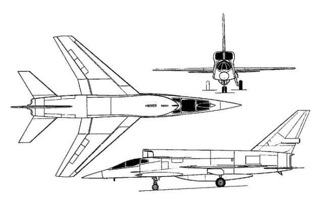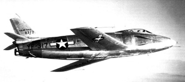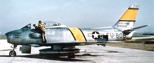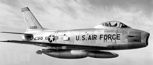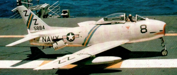
North American FJ Fury

FJ-3 Fury

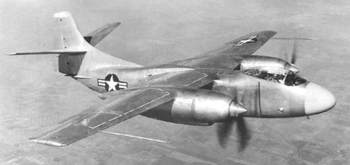
In the summer of 1944, North American Aviation completed the project design for a jet fighter using a wing based on that of the P 51 but with a completely new fuselage with a straight through jet duct from a nose inlet. Two designs were prepared, the second being a longer and heavier aircraft for the USAAF (this was later delayed and finally emerged as the XP 86, the first of the sweptwing Sabre family). The original proposal became the NA 134, ordered by the US Navy as the three XFJ-1 prototypes with the name Fury on January 1, 1945. The Navy became aware of German swept-wing data in the summer of 1945 but, unlike the USAAF, decided not to incorporate it in the new jet fighter.

North American FJ Article

A US Navy contract for the building of three XFJ-1 prototypes was awarded on 1 January 1945. Designed around the General Electric J35 axial flow turbojet, NAA chose a simple configuration with a nose intake and straight through airflow to the engine in the rear fuselage. This necessitated putting the cockpit above the intake ducting and resulted in a short and stumpy looking fuselage. The armament of six 12.7mm machine guns was installed on the sides of the nose. Fuel was housed in the fuselage and in tip tanks on production aircraft.

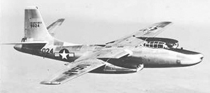
Like the same company’s XB 45 four jet bomber, the XFJ 1 was little more than jet propulsion applied to an advanced traditional airframe, with a laminar wing similar in profile to the P 51. The first flight was made at Inglewood on November 27, 1946, the engine being the 1733 kg (3820 lb) thrust General Electric J35 2 (TGA80) axial. By this time Inglewood was building 100 production FJ 1 Furies, with the Allison J3-A 5 2, virtually the same engine but rerated at 1814 kg (4000 lb) thrust, and with full carrier equipment and six 0.3 in (12.7 mm) guns. Features included small dive brakes above and below the non¬-folding wings, tip tanks, a primitive ejection seat and a ‘kneeling’ nose gear for stacking in a tight nose to tail line below decks. Desig¬nated NA 141, this batch was cut to 30 in 1948. Deliveries of these aircraft began in March 1948 with Allison-built engines and served only with VF 5A, soon restyled VF 51, between November 1947 and May 1949. In 1948 VF-5A (later VF-51) became the first jet unit to complete a seagoing tour of duty, aboard USS Boxer, the first carrier landing having been on March 10, 1948.

The Fury was quickly overtaken by the rapid pace of jet fighter development and remained in front line USN service for only 14 months before being relegated to Naval Reserve units. VF-5A / VF-51 was only operational squadron to fly the aircraft.
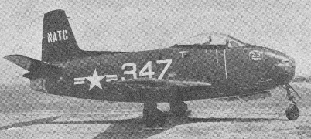
FJ-1 Fury 1948

One of the prototype FJ-1s achieved a speed of Mach 0.87 in 1947 when, the fastest by any US fighter to that point.
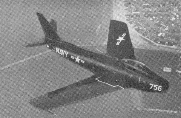
FJ-2

Though the original Fury was no better than several other fighters of the day, the Air Force clearly had made a major advance with the F 86 Sabre, and despite the Cutlass, Skyray and even the later McDonnell Demon the Navy decided to order a naval version of the Sabre in 1950. Confusingly, it decided to designate this FJ 2, instead of F2J, and to perpetuate the name Fury, thereby funds easier to obtain by suggesting that the type was a mere improved FJ 1 instead of a totally new aircraft. The first of the new NA 179 / XFJ-2 Fury prototypes flew on December 27, 1951 (piloted by Bob Hoover). It was essentially an F 86E with four 20 mm (0.79¬in) M 2 guns, an A frame arrester hook, catapult hooks and a lengthened nose leg, the General Electric J47 13 engine remaining.

With successful conclusion of initial carrier qualification trials aboard the USS Midway, this type was ordered into quantity production. Deliveries began in 1954, but only 200 had been completed by 1954 when production switched to the FJ-3.

North American FJ-3 Fury

Carrier qualification was outstanding, and the Columbus, Ohio, factory (previously a Curtiss Wright facility) constructed 300 of the much refined FJ 2 production type, with 2722 kg (6000 1b) thrust J47 2 engine, modified power folding wings, wider track landing gear and APG 30 radar gunsight. Production was assigned lower priority than the F 86F, and when the Korean war ended orders were cut to 200; all were delivered in the first nine months of 1954. All served with shore based Marine fighter squadrons, with bomb racks and, from 1955, the new Sidewinder AAM.

On 3 March 1952, the design of a new Fury shipboard fighter began around the newly-available Sapphire engine, built by Wright and Buick as the J65 2 at 3538 kg (7800 1b) thrust, fed by an enlarged duct which made the fuselage deeper. Assigned the designation FJ-3, the new fighter differed from the FJ-2 primarily in having a redesigned fuselage with a deeper air intake to accommodate the Wright J65 engine, as the US-built version of the Sapphire was known. The fifth FJ-2 was adapted to take the new engine as the NA 196 XFJ-3 and flew on 3 July 1953, and the first of 389 production FJ-3 (NA 194), powered by a J65-W-4 engine rated at 7,650 lb st (3 470 kgp) and carrying an armament of four 20-mm cannon, followed on 11 December 1953. De¬liveries to the US Navy began in September 1954, and, in the following year, the wing slats were discarded in favour of extended leading edges, while, with the 345th aircraft, additional wing stores stations were introduced for 500- or 1,000-lb (227- or 454-kg) bombs or rocket packs. The navy later added 214 NA 215 models with the W 4D engine, but cut this back to an extra 149 only, for a total of 538. In August 1956, as the 538th and last FJ-3 was delivered, a new weapon capability was introduced in the form of the Sidewinder AAM. 80 aircraft subsequently being modified as EJ-3Ms which augmented cannon armament with a pair of the AAMs.

FJ-3 Fury

This fighter/bomber equipped 17 navy and four marine squadrons, and VF 21 in January 1956 became the first combat unit to embark aboard the super carrier Forrestal. (The first FJ 3 unit at sea was VF 173, aboard Bennington, in May 1955.)

From August 1956 a total of 80 FJ 3s were converted to fire Sidewinders as the FJ 3M, while later others were rebuilt as drone targets and as drone (RPY) directors. The FJ¬3D controlled the Regulus 1 ship launched cruise missile, while the FJ 3D2 was parent aircraft to F9F 6K and KDA target aircraft. By 1959 surviving FJ 3s were being rebuilt with a long chord wing, without slats, with integral wing fuel tanks and either three or four weapon pylons. In 1962 the new designations became DF 1C, DF 1D and MF 1C.

In 1953 Columbus, which from the start had a competent and aggressive design and project staff, proposed a completely re-egineered Fury with much enhanced capability. This was soon accepted, and a rebuilt FJ 3 styled NA 208 and with the Navy designation XFJ-4, flew on October 16, 1953. Hardly any part was common to earlier Furies. The wing was much broader and thinner, with mid span ailerons and full integ-ral tankage, inboard high lift flaps and small fences on a fixed leading edge. The sweep was 35 degrees. The very deep reprofiled fuselage combined with the wing to increase internal fuel capacity by M, and with the four underwing pylons all loaded the gross weight was increased by the same proportion compared with the original FJ 2. The tail was thinner, and the vertical surface taller, and much of the engineering was that of the F 100C then in production at the Ohio factory. Main gears had levered suspension and further widened track, and the result was a superior carrier based attack aircraft.

Production FJ 4 (NA 209) Furys flowed from February 1955, the engine being the 3493 kg (7700 1b) thrust J65 16A. The first batch of 150, completed in March 1957, were followed by 222 FJ 4B (71 followed by 151 improved NA 244) which finally closed out production of Sabres and Furys in the United States in May 1958. The FJ 4B had a stiffer wing with six pylons, LABS (Low Altitude Bombing System) for nuclear toss¬-delivery, extra air brakes on the rear fuselage and other changes. It was entirely configured as an attack bomber, and cleared to fire the ASM N 7 Bullpup air to surface guided missile in January 1957.

North American FJ-4B Fury

Five Bullpups could be carried, with the radio command guidance pod on the sixth pylon. In the revised Department of Defense numbering scheme the FJ 4 became the F 1E, and the FJ4B the AF 1E. The AF equipped nine navy and three marine corps attack squadrons, before being progressively transferred to the reserve in 1962 65. A little-¬known research programme involved mixed-power trials using two FJ 4 Furys with North American hydrogen peroxide rockets mounted in a fuselage extension above the normal jetpipe, and with nose extensions housing instrumentation.

Introduced to service in 1957, the FJ-4B was finally retired from the front-line inventory in late 1962 although it continued to fly with second-line squadrons and Reserve units for several more years, the post-1962 designations being F-1C (FJ-3), MF-1C (FJ-3M), F-1E (FJ-4) and AF-1E (FJ-4B). Lesser-used variants were the FJ-3D and FJ-3D2 (DF-1C and DF-1D) drone-director conversions.

Gallery

FJ-1 Fury
Engine: one 4.000-lb (1,814-kg) thrust Allison J35-A-2 turbojet
Maximum speed 547 mph (800 km/h) at 9000 ft (2,745 m)
Initial climb rate 3,300 ft (1,006 m) per minute
Service ceiling 32,000 ft (9,755 m)
Range w/max.fuel 1500 miles (2,414 km)
Empty weight 8,843 lb (4,011 kg)
Maximum take-off weight 15,600 lb (7,076 kg)
Wing span 38 ft 2 in (11.63 m) without tip tanks
Length 34 ft 5 in (10.49 m)
Height 14 ft 10 in (4.52 m)
Wing area 221.0 sq ft (20.53 sq.m)
Armament: six 0.5-in (12.7-mm) machine guns
Crew: 1

FJ-2 Fury
Engine: GE J47

FJ-3 Fury
Engine: 1 x Wright J-65-W-16A, 3470kW
Max speed at sea level, 681 mph (1 096 km/h)
Max speed at 35,000 ft (10 670 m) 623 mph (1 002 km/h)
Initial climb, 8.450 ft/min (42,93 m/see)
Range (clean), 990 mls (1 593 km)
Empty weight, 12,205 lb (5536 kg)
Loaded weight (clean), 17,189 1b(7 797kg)
Span, 37 ft 1 ½ in(11,31 m)
Length, 37ft7in(11.45m)
Height, l3ft 8 in(4,16 m)
Wing area, 302.3 sq ft (28,08 sq.m)

FJ-4
Engine: 1 x Wright J-65-W-16A, 3470kW
Max take-off weight: 9131 kg / 20131 lb
Empty weight: 5 992 kg
Wingspan: 11.91 m / 39 ft 1 in
Length: 11.07 m / 36 ft 4 in
Height: 4.24 m / 13 ft 11 in
Wing area: 31.46 sq.m / 338.63 sq ft
Max. speed: 1094 km/h
Range: 2390 km / 1485 miles
Armament: 4 x 20mm cannon
Crew: 1

FJ-4
Engine: 1 x Wright J-65-W-16A, 7700 lb
Wingspan: 11.91 m / 39 ft 1 in
Length: 37 ft 6 in
Height: 12 ft 8 in
Wing area: 31.46 sq.m / 338.63 sq ft
Max take-off weight: 9131 kg / 20131 lb
Empty weight: 5 992 kg
Fuel capacity external: 583 Imp.Gal.
Max. speed: 687 mph at SL
Max ROC: 7500 fpm
Range: 2390 km / 1485 miles
Max range: 2700 mi
Armament: 4 x 20mm cannon
Crew: 1
Wheel track: 11 ft 7 in
Wheelbase: 16 ft 9.5 in
Underwing hard points: 6

FJ-4B/AF 1E Fury
Powerplant: one 3493-kg (7,700-lb) thrust Wright J65-W-16A turbojet
Maximum speed 1094 km/h (680 mph) at sea level
Service ceiling 14265 m (46800 ft)
Range 4458 km (2,770 miles) with maximum external fuel.
Empty weight 6250 kg (13,778 lb)
Maximum take-off weight 12701 kg (28,000 lb)
Wing span 11.91 m(39 ft 1 in)
Length 11.07 m(36 ft 4 in)
Height 4.24 m (13ft 11 in)
Wing area 3l.46 sq.m (338.66 sq ft)
Armament: four 20-mm cannon
External ordnance 2722 kg (6,000 lb)

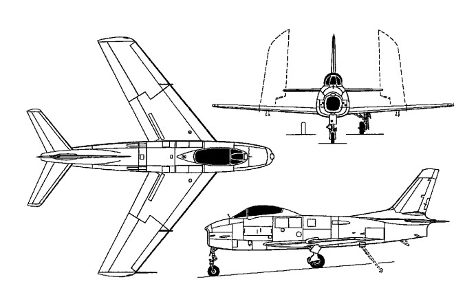
North American FJ-1 Fury
North American FJ-3 Fury

North American F-107

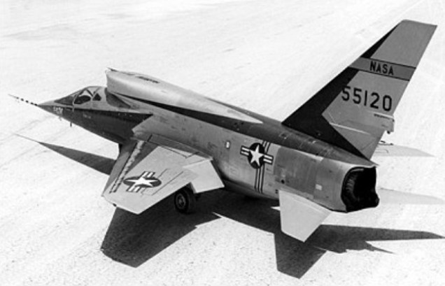
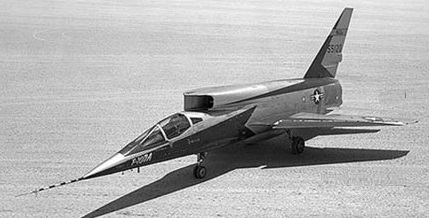
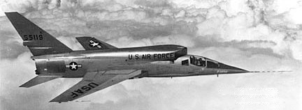
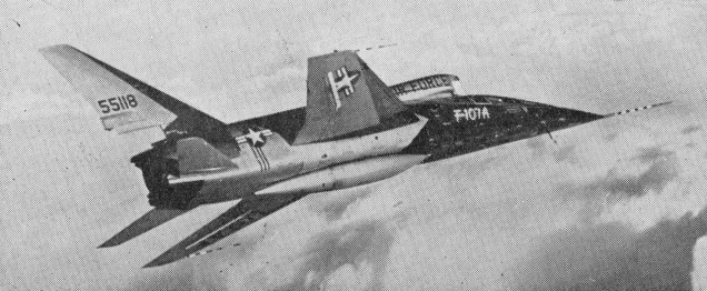
A derivative of the Super Sabre and originally designated the YF-100B, the North American F-107, or company NA-212, was an all-weather fighter-bomber version of the F-100 powered by a 10660kg thrust Pratt & Whitney YJ75-P-9 turbojet.

North American YF-107A 55-5120

A large dorsal arrangement with bifurcated VAID (Variable Area Inlet Duct) inlets inlet was above and behind the cockpit, so positioned to create space in the nose for radar. The F-107 was equipped with a sidestick flight control system.

North American YF-107A 55-5119

Design work began in June 1953 and a year later the USAF ordered nine aircraft (55-5118 to 55-5126), although only three were actually completed (55-5118 to 55-5120). In 1955, the F-107 lost out to the Republic F-105 in a paper competition even though it had not yet flown and its competitor did not, then, have all-weather capability. Thus, the future of the F-107 was already clouded on 10 September 1956 when Robert Baker made the first flight at Edwards AFB, California, in the first of three service-test YF-107As.

The YF-107A was relatively trouble free but despite good performance, the three YF-107As were soon relegated to permanent test status. Features of the aircraft warranting further evaluation included a flush centre-line fuel tank mounted in the indented fuselage bottom, spoilers on the wing surface instead of ailerons, and a one-piece all-moving rudder, later adopted on the A-5 Vigilante attack bomber.

The first YF-107A eventually found itself in a scrap heap, the second is now on display at the Air Force Museum in Dayton, Ohio, and the third was lost in a crash landing while on loan to NACA.
F-107 (Tail number 55-5118) was on display at Pima Air and Space Museum in Tucson.

YF-107A
Engine: 1 x Pratt & Whitney J-75-P-9, 24,500-lb (11,115-kg)
Max take-off weight: 22204 kg / 48952 lb
Empty weight: 16852 kg / 37152 lb
Wingspan: 11.2 m / 36 ft 9 in
Length: 18.5 m / 60 ft 8 in
Height: 6.0 m / 19 ft 8 in
Wing area: 39.7 sq.m / 427.33 sq ft
Max speed: 2200 km/h / 1367 mph
Cruise speed: 700 mph
Range: 1900 km / 1181 miles
Ceiling: 50,000 ft
Armament: 4 x 20mm cannons, 4540kg of weapons
Seats: 1

North American NA-157 / F-93

The North American F-86C developed into the YF-93A and eventually became the third design in the penetration fighter competition with the McDonnell XF-88 and Lockheed XF-90. The YF-93A was a bigger, and bulkier than the Sabre. The nose inlet of the F-86 design was replaced with side-mounted inlets and the fuselage was widened to house a 12835kg thrust Pratt & Whitney turbojet. The result was a larger, heavier machine with longer range and greater load-carrying capacity than the Sabre.

On 9 June 1948, the USAF ordered 118 F-93s, but the order was cancelled a year later. The YF-93A lost its second chance to attain production status when it emerged a poor third in the penetration fighter contest which, as it turned out, did not result in any production contract anyway.

The first of the two YF-93As, also known as the company NA-157, was first flown on 24 January 1950. The two machines underwent various modifications during evaluation, including changes in the shape of their lateral air inlets.

After the USAF was no longer a potential buyer, the two airframes were turned over to the National Advisory Committee for Aeronautics (NACA), where they were employed in various tests until eventually being retired and scrapped.

YF-93A
Engine: 12835kg thrust Pratt & Whitney turbojet
Max take-off weight: 12025 kg / 26511 lb
Empty weight: 16360 kg / 36068 lb
Wingspan: 11.81 m / 38 ft 9 in
Length: 13.44 m / 44 ft 1 in
Height: 4.78 m / 15 ft 8 in
Wing area: 28.43 sq.m / 306.02 sq ft
Max. speed: 1140 km/h / 708 mph
Ceiling: 14265 m / 46800 ft

North American F-86 Sabre / F-95 Dog Sabre

F-86A

To meet a US Army Air Force requirement for a day fighter that could be used also as an escort fighter or dive-bomber, North American submitted a design known as the NA-140.

Two XP-86 prototypes of the NA-140 design were contracted in late 1944, but when German research data on the characteristics of swept wings became available soon after the end of the war, North American sought USAAF agreement to redesign the XP-86 to incorporate swept wings and tail surfaces. This cost a year’s delay, and it was not until 1 October 1947 that the first prototype was flown with flying surfaces swept at 35 degrees, then powered by a Chevrolet-built General Electric TG-180 (or J35-C-3) turbojet of 1701kg thrust; on 25 April 1948, by then re-engined with a General Electric J47 turbojet as the YP-86A, this aircraft exceeded a speed of Mach 1 in a shallow dive.

North American F-86 Sabre Article

The first production version was the P-86A, powered initially by a 2200kg thrust General Electric J47-GE-1 turbojet and flown first on 20 May 1948. A month later USAF redesignation resulted in the P-86A becoming the F-86A and in 1949, by which time it had gained the name Sabre. The new fighter began to enter service with the USAF’s 1st, 4th and 81st Fighter Groups, the 94th Squadron of the 1st Fighter Group receiving the first in February 1949.

On 5 September 1948 at Cleveland, Ohio, an F-86 made an attempt on the world absolute speed record. As a result of faulty timing this flight, estimated to have averaged 669 mph, cannot be claimed as an official record.

F-86A 5 September 1948

F-86A production totalled 554, the majority having 2359kg thrust J47-GE-3, -7, -9, or -13 turbo-jets.

Just six months after it was assigned to duty, the F-86 set a world speed record of 670.9 mph. Later the Sabre beat its own record, upping the bar to 715 mph.

The F-86B (deeper fuselage and larger tyres) and F-86C (redesigned fuselage) did not enter production. The F-86C developed into the YF-93A.

The most extensively built was the F-86D (2,054), a redesigned all-weather/night fighter with a nose radome for all weather fighter duties and rocket armament instead of machine guns. The F-95 designation was assigned initially to the radar-equipped, all-weather interceptor version of the North American F-86 Sabre. The first two YF-95A airframes (50-577/ 578) were hastily assembled in 1949 with the nose configuration but not the radar of production aircraft. The two YF-95As also lacked the missile armament and afterburner of the production machine, being equipped instead with an extremely crude external reheat device at the exhaust for the 2460kg thrust General Electric J47-GE-17 turbojet engine. By the time the first of these machines had been completed and made its first flight on 22 December 1949 with company test pilot Joseph Lynch at the controls, it had been redesignated F-86D.

F-86D / YF-95 Dog Sabre

The F-86D, -K, and -L had a 35 degree sweepback wing with leading edge slats (slots I the F-86L) and trailing edge flaps. The F-86D and -L had a retractable pack of twenty-four 2.75in air-to-air rockets in the bottom of their forward fuselage, the -K having four 20mm cannon.

Subsequent production included the 1950 F-86E (NA-170, -172) with an all-moving tailplane and power-boost controls, and the F-86F (1,539) with a new wing and J47-GE-27 engine. 336 F-86E were built, plus 60 built by Canadair as Sabre Mk.III/IV.

The F-86F was the last day fighter version to be produced by North American and served with many, including Argentina, Nationalist China, Ethiopia, South Korea, Pakistan, Peru, Philippines, Portugal, Saudi Arabia, Spain, Thailand, and Venezuela. Mitsubishi assembled 300 F-86F in Japan for the Japanese Air Self-Defence Force.

The F-86F had the 35 degrees sweptback wings, with tailplane and elevators linked for co-ordinated movements. Fuel tanks are in the fuselage and two or four underwing jettison able tanks were available.

F-86E 51-2721

The sole 1951 F-86G was a provisional designation for an engine test-bed with a modified J47. Production of 406 were completed as F-86D.

The F-86F, QF-86F, RF-86F, and TF-86F (NA-172, -176, -191, -193, -202, -204, -206, -210, -227, -231, -238, -256) of 1952 had new leading edge and boundary layer fences, and six nose guns. First flying on 19 March 1952 (p: George Smith). 2,540 were built, of which one was converted as RF-86F photo-recon and two as two-seat TF-86F (NA-204, -216) trainer (first flying on 5 January 1954). Many were later used as QF-86F targets and drones. The NA-231, 238, and -256 were 300 exports to Japan.

RF-86F 52-4808
TF-86F 52-5016

Destined to be the final production version of the Sabre (477) for the USAF, the F-86H featured a deeper fuselage to accommodate the larger air intake required by an 8,920 lb st (4 046 kgp) General Electric J73-GE-3 engine and permitting a substantial increase in internal fuel capacity. The first F-86H was flown on 30 April 1953 piloted by Joe Lynch, this retaining the slatted wing of the F-86E. Two prototypes were built, 52-1975 and 52-1976. Subsequent aircraft omitted the slats and adopted the extended wing leading edge introduced during F-86F production the final 10 aircraft having both slats and extended wing. Intended for the fighter-bomber role, the F-86H had four underwing stores stations, and could carry a pair of 1,000-lb (463,6-kg) GP bombs or 750-lb (340-kg) napalm bombs in addition to drop tanks, or a 1,200-lb (544-kg) 100-kT nuclear store under the port wing.

F-86H 53-1298

First flying on 4 September 1953, deliveries of the F-86H (NA-187, -203) to the USAF commenced in January 1954, the first 113 having an armament of six 05-in (12,7-mm) machine guns which gave place to four 20-mm cannon in subsequent aircraft, and a total of 473 (plus two pre-series) F-86H Sabres was built with the last being accepted on 11 April 1956.

The F-86K (120) was a simplified version of the F-86D. Evolved from the F-86D specifically for supply to NATO forces under the MDAP, the F-86K differed from its predecessor primarily in having a simpler fire control system and cannon armament which could be supplemented by a pair of AIM-9B Sidewinder AAMs, and was 8’; longer. Development began on 14 May 1953, two F-86D-40s being modified as YF-86K(NA-205) prototypes (52-3630, -3804) and the first of these flying on 15 July 1954. These were subsequently sent to Italy to serve as pattern aircraft for similar aircraft assembled under licence by Fiat. The parent company built 120 F-86Ks, deliveries commencing in May 1955, these being powered by a 147-GE-17B engine rated at 5,425 lb st (2460 kgp) and boosted to 7,500 lb st (3402 kgp) with afterburning, built in armament comprising four 20-mm cannon.

North American F-86K 54-1231

Of the NAA-built F-86Ks (NA-213, -221, -232, -242), 60 were supplied to Norway and 59 to the Netherlands. The first Fiat-assembled F-86K was flown on 23 May 1955, a total of 221 (from North American-built kits of components) being delivered of which 63 were supplied to the Italian air arm, 60 to France, 88 to Germany, six to the Netherlands and four to Norway. The last 45 Fiat-assembled aircraft had the extended wing of the F-86F-40, others being retroactively modified. The Dutch F-86Ks were passed on to Turkey in 1963-64, and, in 1967-68, 47 ex-German aircraft were passed to Venezuela, four of the latter being sold to Honduras in 1969.

In total, 341 were built, plus those license-built by Fiat in Italy, with four 20mm nose cannon.

Production from North American-built kits of components began in Japan, with Mitsubishi leading a group of Japanese companies which first assembled, then increasingly constructed, a total of 300 similar to the F-86F and RF-86F.

The designation F-86L was applied in 1956 to rebuilds (981) from F-86Ds, which introduced a 2’ increased span wing, leading edge slats and electronic equipment integrating them into the American SAGE air defence system.

North American F-86L 52-10143

In 1952 North American installed a 6000lb Avro-Canada Orenda in one F-86A-5 pulled from their own production line as an experimental prototype F-86J (NA-167).

Canadair built a single Sabre Mk.I, based on the original F-86A was followed by 60 F-86Es for the USAF refitted with GE J47, followed by 290 generally similar Sabre Mk 2 fighters, comprising 230 for the RCAF and 60 for the Mutual Defense Assistance Program. These were similar to the F-86E and were fitted with imported J-47-GE-13 engines, rated at 5200 lb.

Canadian production continued with 438 Sabre Mk 4 for the RAF with General Electric engines. Many Mk.2s were brought up to Mk.4 standard.

With the selection in 1948 by the RCAF of the F-86A Sabre as its next-generation fighter it was envisaged from the outset that the indigenous Orenda engine would replace the J47. In the event, this intention was to be frustrated by delays in power plant availability, and it was not until 30 July 1953 that a pre-¬series aircraft was flown with the Canadian engine as the CL-13A Sabre 5.

Almost three years prior to this event, North American had re-engined an F-86A-5 with an Orenda 3 as the F-86A/O, this having flown in October 1950, and the 100th F-86E licence-built airframe completed by Canadair had been similarly powered as the CL- 13 Sabre 3 (alias F-86J) and flown on 4 June 1952.

The Canadair SabreMk.3 was a North American-built F-86E converted for the Avro Orenda engine.

This gave considerably improved performance so the RCAF ordered 470 Sabre Mk.5s based on the F-86F and powered by a 6355 lb Orenda 10.

Twenty-four Canadair Sabre 5 were ordered by Israel and some were completed before the order was cancelled.

Israeli Sabre 5

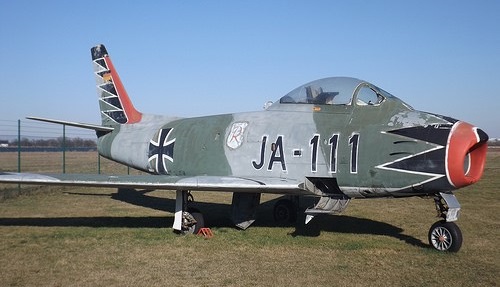
Powered by a 6,355 lb st (2 883 kgp) Avro Orenda 10 turbojet, the Sabre 5 retained the armament of six 05-in (12,7-mm) machine guns and had the slatless extended wing leading edge introduced by the F-86F. A total of 370 Sabre 5s was built, of which 75 were presented to the Federal German Luftwaffe, before production deliveries commenced of what was to prove the definitive Canadair-built model, the CL-13B Sabre 6 first flown on 2 November 1954. This differed essentially from the Sabre 5 in having the two-stage Orenda 14 of 7,275 lb st (3 300 kgp) and initial aircraft had a similar wing to that of the Sabre 5, but later Sabre 6s reinstated wing slats. Of the 655 Sabre 6s built, six were supplied to Colombia, 34 to South Africa and 225 to Federal Germany.

The CL-13C was a Sabre 5 with an area ruled fuselage and the CL-13E was a Sabre 6 fitted with an afterburner.

JA+111 Canadair CL-13B Sabre Mk.6 1625

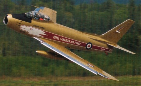
The Sabre 6 served the RCAF from 1950-68. The Sabre 6 with its extra power and slatted wings served in many air forces around the world into the 1970’s, though it stood down in Canada in 1968.

Canadair CL-13 Sabre 6

The Commonwealth Aircraft Corporation in Australia also became involved in Sabre production, modifying the F-86F airframe for two 30mm Adens and the 3402kg thrust Rolls-Royce Avon 26 engine. The more powerful engine involved extensive redesign of the fuselage, including a larger intake.

Commonwealth Aircraft Corporation Sabre Article

The prototype, first flying on 3 August 1953, and the first 22 production Avon-Sabres had imported Avon RA.7 turbojets and retained the Sabre’s leading-edge slats. These were designated Mk.30, first flying on 13 July 1954.

CA-27 Avon-Sabre

They were followed by 20 Sabre Mk 31s with Commonwealth-built Avon 20 and with the slats replaced by extended wing leading-edges.

Subsequently 69 Sabre Mk32 fighters with Australian-built engines were produced.

The wings had a 35 degree sweepback and the tailplane had 10 degrees dihedral. Slotted trailing-edge flaps and tricycle undercarriage were fitted. The main wheels retract inward into the fuselage and the nosewheel retracts rearward. Airbrakes are on each side of the rear fuselage. Fuel tanks are in the fuselage.

Commonwealth Aircraft Corporation Sabre Mk.32

The RAAF received its aircraft 1956, based at Williamstown, NSW.

More than 9,000 Sabres were built; 1,815 of them in Canada.

The German Luftwaffe purchased 225 Sabres from Canadair and in addition received 75 under MDAP arrangements.

This fighter was the prime contender against the North Korean MiG-15, typically flown by Russian and Chinese pilots. The tally at the end of the war was telling, both about American technology and pilot skills. By the end of hostilities, it had shot down 729 MiGs, loosing only 76 Sabres—a victory ration of 10:1. During the Korean War, approximately 22 Canadian pilots were attached to the USAF (United States Air Force) and flew Sabres in combat.

The Royal Thai Air Force received 45 F-86F-30/40 Sabres. Designated ‘Fighter Type 17’, they served from 1961 to 1973.

A radical development of the F-86 Sabre was the FJ Fury naval fighter.

Bob Hoover tested an F-86D that had the horizontal tail located at the bottom of the fuselage. This was a testbed for the future F-100, which would feature a similar configuration. One of the design characteristics of the test bed was that the dive brakes were located on the top of the fuselage instead of the lower section. When the brakes were extended, the plane pitched down and not up as would be the case with the conventional F-86s.

Gallery

F-86A Sabre
Engine: 1 x General Electric J47-GE-3, -7, -9, or -13
Span: 37ft 1in
Length: 37ft 6in
Height: 14ft 9in
Empty Weight: 10,854lbs
Max Take-off Weight: 15,800lbs
Max Speed: 679mph at sea level
Cruising Speed: 533mph
Service Ceiling: 48,000ft
Range: 660miles
Time to 40,000ft: 10.4 mins
Fuel Capacity is 436 gallons internal – external two 100 gallon drop tanks

F-86A/O
An F-86A-5 re-engined to serve as the prototype of the Canadair CL-13 Sabre

F-86D
Engine: General Electric J47-GE-33, 7650 lb with re-heat
Wingspan: 11.30 m / 37 ft 1 in
Length: 12.29 m / 40 ft 4 in
Height: 4.57 m / 15 ft 0 in
Wing area: 287.9 sq ft
Max take-off weight: 20,550 lb
Empty weight: 11,905 lb
Max. speed: 1138 km/h / 707 mph
Ceiling: 16640 m / 54600 ft
Max ROC: 15,600 fpm
Range: 1344 km / 835 miles
Armament: 24 x 69.9mm missiles
Crew: 1

F-86F
Engine: 1 x General Electric J47-GE-27, 5970 lb / 26.3 kN
Wing span: 39 ft 1 in (11.91 m)
Wing area: 287.9 sq.ft
Length: 37 ft 6 in (11.43 m)
Height: 14 ft 8 in (4.47m)
Empty weight: 10,950 lb
Max TO wt: 20.195 lb
Wheel track: 8 ft 3 in
Max level speed: 655 mph at SL
Cruise speed: 603 mph
Service Ceiling: 49,600 ft / 15,100 m
Range: 1270 mi
Ceiling: 50,000 ft
Armament: 6 x 0.5in mg
Bombload: 2 x 1000 lb bombs

YF-86H
Engine: GE YJ73, 9300 lb
Wingspan: 39’1″
Length: 38’8″
Useful load: 8016 lb
Max speed: 692 mph
Range: 1040 mi
Ceiling: 49,000 ft

F-86H
Engine: G.E.C. J73, 8920 lb
Max speed at sea level, 692 mph (1114 km/h)
Max speed at 35,000 ft (10 670 m) 617 mph (993 km/h)
Initial climb, 12,900 ft/min (65,53 m/sec)
Range (two 200-US gal/757-lt drop tanks), 1,040 mls (1674 km)
Empty weight, 13,836 lb (6 276 kg)
Loaded weight (with two drop tanks), 21,852 lb (9912kg)
Span, 39ft 1½ in(l1,92m)
Length, 38ft l0in(11,84 m)
Wing area, 313.37 sq ft (29,11 sq.m)

F-86K
Engine: General Electric J47-GE-17B, 7450 lb with re-heat
Span, 37 ft 1.5 in (11,31 m)
Length. 40 ft 11 1/8 in (12,47 m)
Height, 15 ft0 in (4.57 m)
Wing area. 287.9 sq ft (26,7 5 sq.m)
Empty weight. 13,367 lb (6063 kg)
Loaded weight (clean), 18,379 lb (8337kg)
Max speed at sea level, 692 mph (1114km/h)
Max speed at 40,000 ft (12 190 m), 612 mph (985 km/h)
Initial climb, 12.000 ft/min (60,96 m/sec)
Range (with two 120-US gal/454-lt drop tanks), 744 mls (1197 km)

F-86L
Engine: General Electric J47-GE-33, 7650 lb with re-heat
Wingspan: 39’1″
Length: 40’3″

Canadair Sabre Mk.I

Canadair Sabre Mk.2
Engine: GE J47-GE-13, 5200 lb

Canadair Sabre Mk.3
Engine: Avro Orenda

Canadair Sabre Mk.4
Engine: GE J47-GE-27, 5800 lb

Canadair Sabre Mk.5
Engine: Orenda 10, 6500 lb

Canadair F-86 Sabre 6
Engine: Avro Canada Orenda 14 turbojet, 7275 lb
Dimensions as for F-86A
Wing Span: 37 ft 11.5 in
Empty weight; 10,618 lb / 4816 kg
Loaded weight (clean): 14,613 lb / 6628 kg
MTOW: 17,560 lb / 7965 kg
Engine: Orenenda 14, 7275 lb / 3300 kg
Max speed at sea level, 710 mph (1143 km/h)
Max speed at 36,000 ft (10 975 m) 620 mph (998 km/h)
Range: 363 miles / 584 km
Ferry range: 1486 miles / 2391 km
Service ceiling: 54,700 ft / 16,460 m
Initial climb, 11,800 ft/ min (59,94m/sec)
Rate of Climb: 35,000 ft / 10,670m in 4 min 42 sec
Armament: 6 x 0.50in (12.7mm) mg , 1602 rounds total (267 rounds per gun)

CA-27 Avon-Sabre
Engine: Commonwealth Rolls-Royce Avon 26, 7500 lb.s.t
Wingspan: 37 ft 1 in
Wing area: 312 sq.ft
Length: 37 ft 6 in
Height: 14 ft 5 in
Wheel track: 8 ft 4 in
Empty weight: 12,000 lb
MTOW: 17,300 lb
Max speed: 700 mph at SL
Max ROC: 12,000 fpm
Service ceiling: 50,000 ft
Max range: 1150 mi
Armament: 2 x 30mm Aden cannon
Bombload: 2 x 1000 lb

North American F-86 Sabre
North American F-86D / YF-95 Dog Sabre

North American AJ Savage / A-2 Savage / NA-146 / NA-163 / A2J

North American XA2J-1 124439

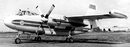
The first heavy attack type to see service from aircraft-carriers of the US Navy, the North American AJ Savage was developed (as the North American NA-146) using two Pratt & Whitney radial engines, augmented by a tail-mounted Allison J33 turbojet. In practice the type saw only limited use in the strategic bombing role for which it had been designed, being replaced from the mid 1950s onwards by the Douglas A3D Skywarrior, but several were subsequently modified to serve as inflight-refuelling tankers with a hose-and-reel unit in place of the turbojet.

North American XA2J-1 Article

In order to meet the specification’s demands a large aircraft was required, this in turn dictating the need far an unusual composite powerplants configuration – a pair of Pratt & Whitney R-2800 Double Wasp radials as the primary engines augmented by an auxiliary Allison J33 turbojet in the lower rear fuselage.

This third engine was intended to provide a high speed ‘dash’ capability during the attack phase of the aircraft’s operation and for extra boost on takeoff when required. Other features included shoulder mounted folding wings, tricycle undercarriage, wing tip fuel tanks and (on the first models) dihedral tail planes.

An initial contract for three prototype XAJ-l (NA-146) aircraft was awarded to North American in late June 1946, and construction of these got under way almost immediately although more than two years were to elapse before the Savage took to the air for the first time on 3 July 1948. In its original guise the Savage was manned by a crew of three and was intended to carry a 4536-kg (10,000-lb) weapon load in an internal bomb bay in the aircraft’s belly. The three prototypes (121460 to 121462), were fitted with a flat horizontal tail.

North American AJ-1

These were followed by 55 initial production AJ-1s (NA-156, -160, and -169, 122590 to 122601, 124157 to 124186, and 124850 to 124864), the first one flying on 10 May 1949. The horizontal tail with dihedral. Production-configured aircraft began to enter service with Composite Squadron VC-5 in mid-September 1949, but it was not until the end of August 1950 that this unit was considered operationally ready, this marking the climax of several months of sea-borne trials aboard the USS Coral Sea. The AJ-1 was re-designated A-2A in 1962. The first carrier landings were performed aboard USS Constellation in August 1950. The first variant to see service with the US Navy was the AJ-l, of which 40 were built, and these were followed by 55 examples of the AJ-2 (NA-163and NA-184, 130405 to 130421, and 134035 to 134072) which featured slightly more powerful radial engines as well as increased fuel capacity, a slightly longer fuselage and a taller fin and rudder to improve handling qualities. The AJ-2 first flew on 19 February 1953 and was re-designated A-2B in 1962.

North American AJ-2 Civil borate bomber N101Z

This photo is AJ-2 130418, probably taken in 1971, possibly at Bridgeport CT. It is wearing markings applied by Avco Lycoming while used an engine test-bed, registered N68667. Following its naval use, it was used as a fire bomber in Oregon, registered N101Z, before going to new owners. In 1984 it was flown to the Naval Air Museum at Pensacola and is now on display in USN markings.

Preceding the AJ-2 bomber was the photo-reconnaissance AJ-2P (NA-175 and NA -183, first flight 30 March 1952) equipped with 18 cameras for day and night photography at high and low altitudes, photo-flash bombs in the weapons bay, automatic control of most of the cameras, the associated electronics equipment in a modified nose and additional fuel capacity. Four US Navy combat squadrons were still operating the AJ-2 in 1958 and these received AJ-2Ps.

A total of 30 AJ-2Ps was built, 128043 to 128051, 129185 to 129195, 130422 to 130425, and 134073 to 134075, this being the last model to see squadron service, not being retired from the active inventory until the beginning of 1960. The AJ-2P has distinctive radar “thimble” nose and zero-dihedral stabilizer.

AJ-2P Savage

A number of AJ-1s and AJ-2s were converted to flight refuelling tankers with a hose-and-reel unit installed in the weapons bay. The few Savages still in service in September 1962 when all USAF and USN aircraft designations were combined into the existing Air Force system were redesignated A-2A (AJ-1) and A-2B (AJ-2).

AJ Air Tankers of Van Nuys CA converted two as fire fighters after removing the J-33 in the tail, showing one in action with no big prop spinners and a firefighting scheme with a big #88 about 1988.

In 1948 North American began work on the NA-163 turboprop-powered derivative of the AJ-1 Savage, two prototypes being ordered in September of that year. The US Navy specified major changes, including deletion of the Allison J33 booster engine, and the first prototype North American XA2J-1, 124439, did not fly until 4 January 1952. Development was hampered by problems with the Allison XT40-A-6 engines, each of which comprised two T38 engines driving contra-rotating propellers through a gearbox, allowing either T38 in each unit to be shut down for long-range cruise. The three-man crew was provided with a pressurised cabin and defensive armament comprised two 20mm guns in a remotely-controlled barbette. Maximum offensive load was 4911kg of bombs. The completed second prototype, 124440, was never flown. One ended up being burned in a fire-fighting demo at Edwards AFB in 1962.

AJ-2 Savage
Engines: 2 x 2,500-hp (1864-kW) Pratt & Whitney R-2800-48 radial and 1 x 4,600-lb (2087-kg) thrust Allison J33-A-10 turbojet
Max speed: 628 km/h (390 mph)
Service ceiling: 12190 m(40,000 ft)
Range 3540 km (2,200 miles)
Empty wt: 12247 kg (27,000 lb)
Maximum take-off wt: 23396 kg (51,580 lb)
Wing span 21.77 m (71 ft 5 in)
Length 19.23 m (63 ft 1 in)
Height 6.22 m (20 ft 5 in)
Wing area 77.62 sq.m (835.5 sq ft)
Armament: up to 4536 kg (10,000 lb) of bombs carried internally.
Crew: 3

AJ-2
Engines: 2 x Pratt & Whitney R-2800-44W, 1790kW + Allison J33-A-19 auxiliary turboprop, 2087kg
Max take-off weight: 23973 kg / 52852 lb
Wingspan: 22.91 m / 75 ft 2 in
Length: 19.20 m / 62 ft 12 in
Max. speed: 758 km/h / 471 mph
Crew: 3

AJ-2P Savage
Carrier-based photo-reconnaissance and attack bomber
Engines: 2×2,400 h.p. Pratt & Whitney R2800-48W and 1 x 4,600 lb. thrust Allison J33-A-10
turbojet.
Wingspan: 71 ft. 5 in
Length: 65 ft.
Loaded weight: 55,000 lb.
Max. speed: 425 m.p.h.
Ceiling: 40,000 ft.
Typical range: More than 3,000 miles at 290 mph
Payload: 12,000 lbs internal
Operational equipment: 18 cameras
Armament: 2 x 20mm cannon
Crew: 3

XA2J-1
Engines: 2 x Allison XT40-A-6 turboprops
Armament: 2 x 20mm cannons, 4900kg of weapons
Crew: 3

North American A3J / A-5 Vigilante

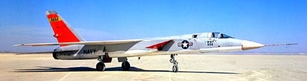
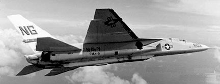
RA-5C

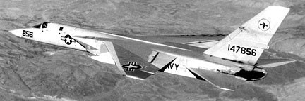
The Vigilante was designed as a Mach 2 carrier-based attack aircraft capable of carrying nuclear or conventional bombs. The airframe has high-set wings sweptback at 37.5 degrees, and sweptback tail surfaces, both horizontal and vertical surfaces consisting of one-piece all-moving surfaces. There are three section spoilers instead of ailerons. Three-section leading-edge flaps are on each wing. There is a flap blowing system for the trailing-edge flaps. The wingtips fold upward, fin-tip sideways and fuselage nose upward for stowage on board ship. The engines are mounted side-by-side in the rear fuselage, with wedge-shape air intakes on each side of the fuselage. A tricycle undercarriage has a single wheel on each unit, the nosewheel retracts inward and mains retract inward.

North American A3J / A-5 Vigilante Article

The first prototype flew on 31 August 1958.

A3J-1 Vigilante no.1

Two YA3J-1 (NA-233, -247 / 145157/145158) were built, powered by 16150 lb GE YJ79-GE-2. First deliveries were made to the US Navy were made in June 1961 for service trials. They became YA5-A in 1962.

57 production A3J-1 (NA-247, -258, -263, -269, -272) attack aircraft were delivered to the US Navy during 1960, becoming operational on board USS Enterprise in February 1962 (146694/146702, 147850/147863, 148924/148933, 149276/149299). These became A-5A.

A-5A 147856
A-5A 147858

In 1962 six A3J-2 (NA-269) were built (149300/149305) with Additional fuel in a humped fuselage-top decking. First flying on 29 April 1962, they became A-5B.

First flying on 30 June 1962, 55 A3J-3P (149306/149317, 150823/150842, 151615/151634, 151726/151728, 156608/156643) were built as a long-range photo-recon version of the A3J-2, plus 59 converted A-5A and A-5B. These became A-5C/RA-5C in 1962.

North American A-5C 156638
North American RA-5C

The other major version of the Vigilante was the RA-5G, a reconnaissance type of which more than 90 were built as new; most of the A-5A were subsequently converted to this standard.

Gallery

A3J-1
Engines: 2x General Electric J79-GE-2, 10,500 lb (15,000 with reheat)
Wingspan: 53 ft
Length: 73 ft
Height: 20 ft

A3J-1 / A-5A
Engines: 2 x J-79, 17000 lb
Wingspan: 53’0″
Length: 76’6″
Max speed: 1385 mph
Cruise speed: 805 mph
Stall: 156 mph
Range: 985 mi
Ceiling: 43,800′

A3J-3P / A-5C / RA-5C
Engines: 2 x J79, 17860 lb
Length: 76’6″
Useful load: 42,090 lb
Max speed: 1290 mph
Cruise speed: 783 mph
Stall: 154 mph
Range internal fuel: 547 mi
Range max fuel: 944 mi
Ceiling: 48,400′
Combat radius: 1,500 mi

RA 5C Vigilante
Engines: 2 x GE J-79-8(N) turbo-jet, 75.6kN
Max take-off weight: 27300 kg / 60187 lb
Wingspan: 16.2 m / 53 ft 2 in
Length: 22.3 m / 73 ft 2 in
Height: 5.9 m / 19 ft 4 in
Wing area: 65.0 sq.m / 699.65 sq ft
Max. speed: M2+
Ceiling: 18300 m / 60050 ft
Range: 3700 km / 2299 miles
Crew: 2

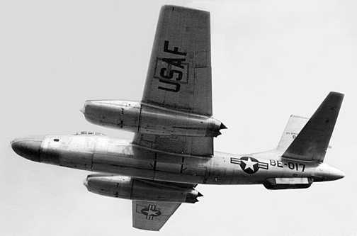
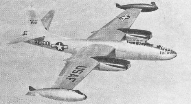
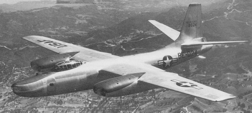
North American B-45 Tornado

RB-45C

In 1943, aware of Nazi Germany’s advances in the field of jet propulsion, the Army Air Forces (AAF) asked the General Electric Company to devise a more powerful engine than its prospective axial turboprop. This eventually brought about the production of the J35 and J47 turbojets. In 1944, 1 year after the jet engine requirements were established, the War Department requested the aircraft industry to submit proposals for various jet bombers, with gross weights ranging from 80,000 to more than 200,000 pounds, and only 4 contractors answered the call. The design was frozen in early 1945.

North American B-45 Tornado Article

Pressed for time, the AAF in 1946 decided to skip the usual contractor competition, review the designs, and choose among the proposed aircraft that could be obtained first. The multi-jet engine B-45, with the understanding that if a less readily available bomber was to prove superior enough to supplant it (which the Boeing XB-47 did), that aircraft would also be purchased.

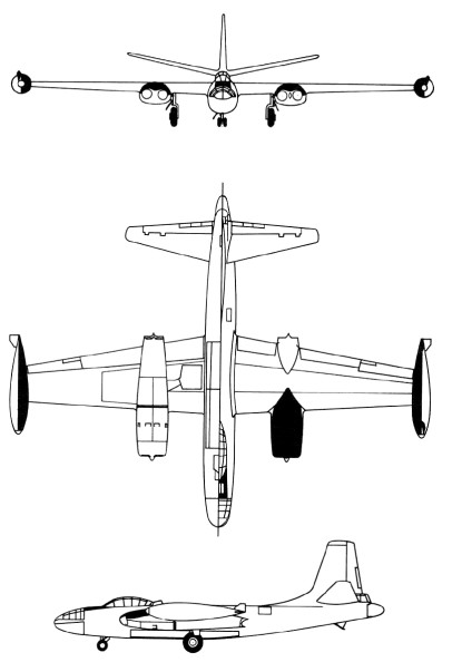
The design was generally conventional, though the main gears had very large single wheels which retracted sideways into the wing roots. In normal bomber versions the bomb aimer/navigator occupied the capacious pressurized nose, the two pilots sitting in a tandem fighter like cockpit farther aft and above, with a large multi pane canopy. The crew door was on the left side of the forward fuselage. A gunner was housed in a pressurized tail compartment.

The first flight was on 17 March 1947 (piloted by George Krebs) and testing of the XB-45 prompted pre-production changes. North American Aviation redesigned the nose panel, increased the aircraft’s stabilizer area, and lengthened the tailplane by nearly 7 feet.

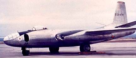
North American XB-45 45-59479
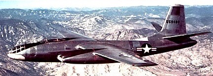
North American XB-45 45-59480

In August 1948, 22 of the 90 B-45s, ordered less than 2 years before, reached the newly independent Air Force. However, the B-45’s weight and takeoff distances had increased, and numerous structural and mechanical defects appeared.

In November 1948 the B 45A (NA-147) went into service with the 47th Bombardment Group of the USAF, later based in England. Ninety-six were built (47-001/097, the last one of which was a static test-frame.

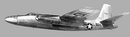
North American B-45A 47-011

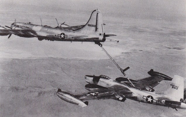
In June 1951 an RB-45 became the first jet bomber to be refuelled in flight by a Boeing KB-29.

Boeing KB-29 and North American RB-45 Tornado

The DB-45A were conversion of B-45A as guided missile director. The JB-45A 47-096 and JB-45C of 1950 were engine test beds for Westinghouse and General Electric.

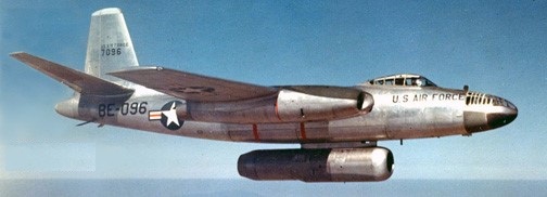
North American JB-45A 47-096
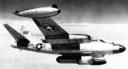
North American JB-45C 48-009

The fourteen TB-45A were target tugs modified from B-45A.

The B-45B was a project only, none were built.

Ten B-45C (NA-153 48-001/010) were built in 1950. The DB-45C were conversions of B-45A as guided missile director.

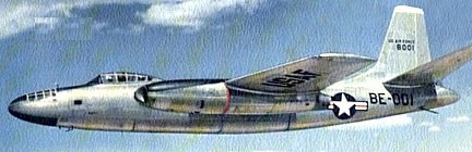
North American B-45C 48-001

Thirty-three RB-45C and JRB-45C (NA-153 48-011/043) were built in 1949 for Photo-recon.

North American RB-45C 48-024
North American JRB-45C 48-017

As the B-47’s future production had become certain, in mid-1948 the Air Staff questioned the B-45’s value as well as its potential use. As President Truman slashed Air Force expenditures, the programmed production of B-45s was reduced to a total of 142 aircraft at a unit cost of US$1,081,000.

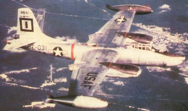
Only 96 B 45As were built, plus 10 of the stronger and more powerful B 45C which was disting¬uished by large wingtip tanks. Many A models were modified to B 45C standard. The final 33 aircraft were RB-¬45C camera aircraft, some of which (unlike the bomber versions) operated over Korea. Some had water injection tanks hung under the twin engine nacelles, jettisoned after take off.

Although continuously plagued by engine problems, component malfunctions, lack of spare parts, and numerous minor flaws, the B-45 regained importance. The B-45 was designed to carry both conventional and atomic bombs. Under the code name of Backbreaker, several distinct atomic bomb types and large amounts of new electronics support equipment had to be fitted in place of the standard components. In addition, the 40 B-45s allocated to the Backbreaker program also had to be equipped with a new defensive system and extra fuel tanks. Despite the magnitude of the modification project, plus recurring engine problems, atomic-capable B-45s began reaching the United Kingdom in May 1952, and deployment of the 40 aircraft was completed in mid-June, barely 30 days behind the Air Staff deadline.

B-45C Tornado

The British and American military intelligence services collaborated under utmost secrecy. Thus in 1952 four American RB-45C reconnaissance aircraft, wearing British colours but without registration marks, operated from RAF Sculthorpe on photo-missions over East Germany and other Eastern-bloc countries. Very up-to-date for the time, the RB-45C was equipped with 12 cameras. The aircraft were based at Sculthorpe in January 1952 as a detachment of the 91st Strategic Reconnaissance Wing of SAC.

The last B 45s were withdrawn from combat duty in mid-1958. The entire contingent, Backbreaker and reconnaissance models included, was phased out by 1959. Yet, the B-45 was the Air Force’s first jet bomber and as the first atomic carrier of the tactical forces.

RB-45C Tornado

Gallery

XB-45 / NA-130
Engines: 4 x GE TG180, 4000 lb
Speed: 536 mph

B-45A Tornado
Engines: 4 x GE J47, 5200 lb
Wingspan: 89’1″
Length: 75’4″
Max speed: 575 mph
Cruise speed: 455 mp
Crew: 3-4

B 45C Tornado / NA-153
Engines: four 2359 kg (5,200 lb) thrust General Electric J47 GE 13/15 turbojets (some with water injection 2722 kg/6,000 lb)
Wing span over tip tanks: 29.26 m (96 ft 0 in)
Length: 22.96 m (75 ft 4 in)
Height 7.68 m (25 ft 2 in)
Wing area: 109.2 sq.m (1,175.0 sq ft)
Empty weight 22182 kg (48,903 lb)
MTOW: 51235 kg (112,952 lb)
Max speed 932 km/h (579 mph) at low level
Service ceiling: 13165 m (43,200 ft)
Range 3074 km (1,910 miles)
Armament: two 12.7 mm (0.5 in) machine guns in tail turret
Internal bombload of up to 9979 kg (22000 lb).
Crew: 3

North American T-2 Buckeye / Rockwell T-2

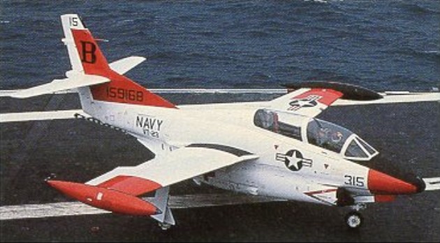
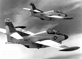
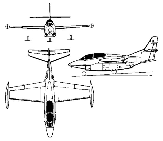
With a requirement in 1956 for a multi-role jet trainer, the US Navy awarded North American a contract to build its North American NA-241 design, which combined proven components and equipment from earlier aircraft manufactured by the company. Ordered as the T2J-1 (later T-2A), this trainer combined a wing derived from the FJ-1 Fury and the control system of the T-28C Trojan with a single 1542kg thrust Westinghouse J34-WE-36 turbojet, and accommodated the instructor and pupil in tandem, seated (eventually) on zero-zero ejection seats.

North American T-2 Buckeye Article

The first of six initial production T-2As was flown on 31 January 1958 and deliveries to the US Navy began in July 1959, by which time the name Buckeye had been allocated to this trainer. Equipping US Navy Training Squadrons VT-4, -7, -9 and -19, a total of 217 T-2As was built.

Two T-2A were modified to serve as YT-2B prototypes, in which the single J34 turbojet was replaced by two 1361kg thrust Pratt & Whitney J60-P-6 turbojets. The first was flown on 30 August 1962, being followed by 97 similar T-2B aircraft , 152382-152391, 152440-152475, 153538-153555, and 155206-155238 (NA-280, -288, -291, -294, -310) from 1962.

Rockwell-North American T-2B

Final production version was the 1958 T-2C (NA-307, -318, -332, -340) which introduced General Electric J85 turbojets, preceded by a single YT-2C prototype conversion from a T-2B.

A total of 273 was built under US Navy contracts before production ceased, comprising 231 T-2Cs for navy use (155239-155241, 156686-156733, 157030-157065, 158310-158333, 158575-158610, 158876-158911, 159150-159173, 159704-159727) plus 12 T-2D and 30 T-2E aircraft in 1969, procured for Venezuela and Greece respectively.

The DT-2C was a drone director conversion.

It was to be re¬tired in favour of the more advanced T 45 Goshawk which has cockpit instrumentation similar to the F/A-18 Hornet.

Gallery

T 2A
Engine: 1 x 3,400 lbs.t. (1542 kpg) Westinghouse J34 WE 36
Max speed, 492 mph (792 kph) at 25,000 ft (7620 m)
Cruise, 422 mph (679 kph)
Initial climb, 5,000 fpm (25.4 m/sec)
Service ceiling, 42,500 ft (12 950 m)
Range, 550 mls (885 km)
Empty weight, 6,893 lb (3 127 kg)
Loaded weight, 9,916 lb (4498 kg)
Span, 36 ft (10.97 m)
Length, 38 ft 8 in (11.78 m)
Wing area, 255 sq.ft (23.7 sq.m)

T 2B
Engines: 2 x 3,000 lbs.t. (1316 kgp) J60.
MTOW: 12,300 lb
Top speed: 545 mph

YT-2B / T 2B
Engines: 2 x J60-P, 3,000 lbs.t. (1316 kgp)
Useful load: 3842 lb
Speed: 540 mph
Ceiling: 44,000 ft

T-2C / DT-2C
Engines: 2 x General Electric J85-GE-4 turbo-jet, 13.1kN / 2950 lb
Max take-off weight: 5978 kg / 13179 lb
Empty weight: 3681 kg / 8115 lb
Wingspan: 11.63 m / 38 ft 2 in
Length: 11.79 m / 38 ft 8 in
Height: 4.51 m / 14 ft 10 in
Wing area: 23.70 sq.m / 255.10 sq ft
Useful load: 5065 lb
Max speed: 521 mph
Cruise speed: 465 mph
Ceiling: 13535 m / 44400 ft
Range: 1465 km / 910 miles
Crew: 2

T-2J
Engines: 2 x Westinghouse J34, 3400 lb
Wingspan: 36’0″
Length: 38’4″
Max speed: 494 mph
Cruise speed: 417 mph
Stall: 67 mph
Range: 967 mi

North American T-2 Buckeye

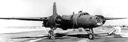
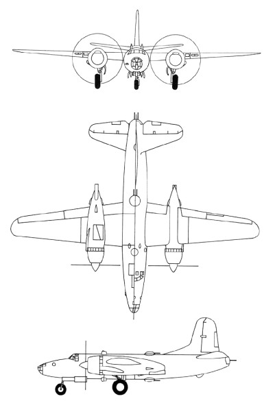
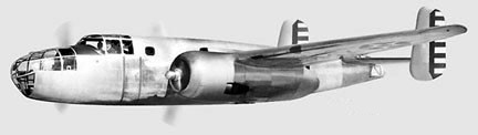
North American NA-63 / XB-28

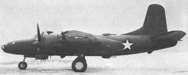
Envisaged originally as a high-altitude version of the B-25 Mitchell, the North American NA-63 (XB-28) emerged finally as an almost entirely different aircraft. With single vertical tail surfaces and a circular-section fuselage with a pressure cabin for the five-man crew, the XB-28 was powered by two 1491kW Pratt & Whitney R-2800 radials and bomb bay capacity was 1814kg and -28A with R-2800-27. Dorsal, ventral and tail turrets, each containing two 12.7mm machine-guns, were remotely controlled from the cockpit; three similar forward-firing weapons were also fitted.

North American XB-28 40-3056

Of three prototypes ordered in February 1940, the first flew in April 1942 (40-3056), the second (40-3058), with a reconnaissance camera installation, crashed during the test programme and the third was cancelled. Although the XB-28 achieved a maximum speed of 599km/h at 7620m and could carry a 272kg bomb load for 3283km, production orders were not placed when no particular need for such a plane was found. A third prototype was unbuilt.

XB-28 / NA-63
Engines: two Pratt & Whitney R-2800-11, 11491kW / 2000 hp
Wingspan: 22.12 m / 72 ft 7 in
Length: 17.20 m / 56 ft 5 in
Wing area: 62.80 sq.m / 675.97 sq ft
Max take-off weight: 16226 kg / 35772 lb
Empty weight: 11611 kg / 25598 lb
Useful load: 10,165 lb
Max speed: 372 mph
Cruise speed: 411 km/h / 255 mph
Stall: 86 mph
Ceiling: 34,600 ft
Range: 3284 km / 2041 miles

XB-28A / NA-67
Engines: two Pratt & Whitney R-2800-27, 11491kW / 2000 hp
Wingspan: 22.12 m / 72 ft 7 in
Length: 17.20 m / 56 ft 5 in
Wing area: 62.80 sq.m / 675.97 sq ft

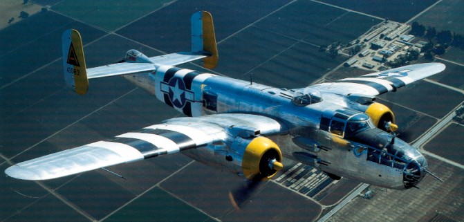
North American B-25 Mitchell / PBJ

B-25J

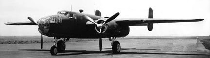
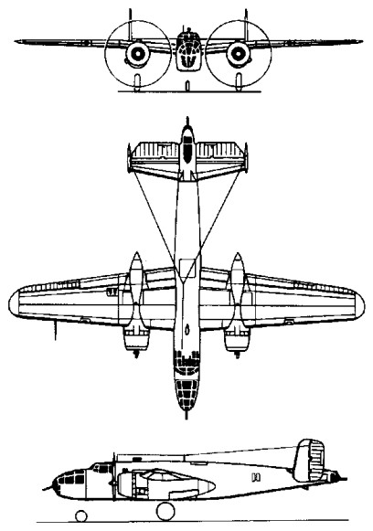
Built as a private venture, the NA-40-1 prototype flew in January 1939. The design was extensively modified as NA-62 after Wright Field testing and 1700hp R-2600s installed.

North American B-25 Article

Ordered into production in 19 August 1939 it took just fifty-three weeks after receiving the initial contract before the first prototype took to the air. The initial order for 24 as B-25: 40-2165 to 40-2188. The prototype of the B-25 was flown for the first time on August 1940. The first of these 184 B-25 Mitchell entered service in 1941.

North American B-25 Straight-wing, narrow tails 40-2165

Flying the B-25 Mitchell

It and the first few B-25s off the production line had wings with a constant dihedral from the fuselage to the tips. Only after the 10th one were the wings redesigned with the characteristic gull configuration. Its armament included four .30-caliber machine guns, one in the nose and three amidships, and a single .50-caliber gun in the tail. The usual bomb load was 2,000 pounds with a maximum overload of 3,600 pounds. Large scale production began immediately and early models were in service by the time America entered the war in December 1941.

North American B-25A

The B-25A was fitted with self-sealing fuel tanks and armor for the pilot. The B replaced the midship and tailguns with electrically operated turrets. Each turret had two .50-caliber machine guns. The lower turret was remote-controlled. 120 of the 1941 B-25B (NA-62B) were built; 40-2229 to 40-2242, and 40-2244 to 40-2348, of which 23 to went to the RAF/RAAF.

North American B-25B 40-2321

The C and D were provided with automatic flight control equipment.

North American B-25C 41-12800

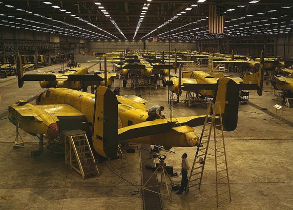
The B-25C was the first version of the Mitchell to be mass-produced. Following the completion of the initial B-25, B-25A, and B-25B contracts, a number of contracts were awarded to North American for 1625 B-25Cs to be built at its Inglewood factory. At the same time, an additional contract was issued for 2290 essentially identical B-25Ds, to be built at a new North American plant in Kansas City, Kansas.

The first B-25C contract was approved on September 24, 1940 for 863 aircraft under the company designation NA-82. On June 24, 1941, the Netherlands government ordered an additional 162 aircraft under the designation NA-90 which were later built as the B-25C-5. Lend-Lease funds financed contracts signed on January 23, 1942 for 150 NA-94 (B-25C-10) for Britain and 150 NA-93 (B-25C-15) for China. However, these allotments were not followed in the delivery of actual aircraft.

The B-25C was outwardly almost identical to the B-25B. It introduced the R-2600-13 Double Cyclone engine with Holley 1685HA carburetors in place of the earlier Bendix Stromberg PD-13E-2 units. The Bendix carburetors were favored because of their easier maintenance, but they required more careful anti-icing procedures. De-icer and anti-icing systems were added, and a Stewart-Warner cabin heater was added in the left wing. A 24-volt electrical system was also added.

The armament of the B-25C was the same as that of the B-25B, namely a single 0.30-inch machine gun in the nose, two 0.50-inch machine guns in the dorsal turret, and two 0.50-inch machine guns in a retractable ventral turret. The ventral turret was often removed in the field.

The B-25C introduced a new type of tail skid underneath the extreme rear fuselage, a solid unit which replaced the spring-loaded tail skid of earlier versions. This type of tail skid was retained throughout the Mitchell production run.

On the earlier B-25s, the exhaust pipe coming out of the back of the engines extended all the way to a position underneath the forward leading edge of the wing. On the B-25C, the exhaust pipes were considerably shortened, and terminated immediately behind the engines.

The fuel was carried in four tanks in the inner wing panels, with a total capacity of 670 US gallons. In addition, a 515-gallon tank could be installed in the bomb bay for ferrying purposes, bringing total fuel capacity to 1255 US gallons.

Beginning with B-25C serial number 41-12817, a small transparent scanning blister was installed above the navigator’s station. At this time, the turrets were changed to Bendix Amplidyne type, and a carbureter air filter was added. Changes were made so that an additional 304 US gallons of fuel could be carried in auxiliary cells in the outer wing panels, for a total of 974 US gallons.

The B-25C-1 production block introduced under-wing bomb racks which could accommodate six to eight 100- to 325-pound bombs. In addition, provisions were made for a rack underneath the fuselage capable of carrying a short 22.4-inch torpedo weighing 2000 pounds. If the torpedo was carried, no bombs could be, although a bomb bay fuel tank could be used. The Mitchell was employed only in limited numbers as a torpedo plane against Japanese shipping. However, extensive use was made of the external wing racks, which could carry six to eight bombs of 100-325 pounds in weight.

Beginning with the B-25C-5 production block, the 0.30-inch nose gun was removed and replaced by a flexible 0.50-inch machine gun in the extreme nose and a fixed 0.50-inch machine mounted on the starboard side of the nose and firing through a hole cut into the side of the Plexiglas glazing. At the same time, better winterization provision were made.

The B-25C-5 production block also introduced a new type of engine exhaust. The B-25B and earlier C versions had a problem with bright spurts of flame being emitted from the exhaust, a dead giveaway during night operations. This problem was so bad that the Mitchell had to be restricted from night operations where enemy aircraft could be expected. In these earlier versions, the exhaust from each cylinder head was gathered by a collector ring, which directed the exhaust to the outside via a single pipe on the side of the nacelle away from the fuselage. Several different exhaust modifications were tried out in an attempt to alleviate this problem. The most effective arrangement was found to be a the replacement of the single exhaust pipe by a set of “finger”-type flame dampening exhaust collectors which ported the exhaust through groups of small rectangular outlets that stuck out underneath the trailing edge of the cowl flaps. These “finger”-type flame dampeners were installed on the production line beginning with the B-25C-5 production block. These were fairly effective flame quenchers, but they suffered considerable cracking and few B-25Cs reached combat zones without the replacement of these finger exhausts by full collector rings or by the later Clayton S-shaped stacks that were introduced on the -15 production block.

The B-25C-10 production block introduced an AM remote reading compass, provisions for additional cabin heating, and an improved scanning lens for the sig.

Beginning with the B-25C-15 production block, the exhaust collector ring was replaced with Clayton “S”-shaped flame dampening stacks attached to each individual cylinder. Cutouts and fairings were added to the cowling panels where each of the stacks protruded, creating a rather cluttered cowling shape. These protrusions introduced a slight speed penalty, but this was considered an acceptable tradeoff in view of the better flame dampening that was achieved. This feature was provided on all subsequent Mitchells. However, the new exhaust system was not all that popular with Mitchell crews, since it resulted in an increase in cockpit noise as compared to the old arrangement in which collector rings ported the exhaust to the outboard side of the nacelles.

At the same time, emergency hydraulic landing gear lowering devices were provided. The fuel capacity consisted of four tanks in the inner wing panels, with a total capacity of 670 US gallons. In addition, a 515-gallon tank could be installed in the bomb bay for ferrying purposes, bringing total fuel capacity to 1255 US gallons. Later versions had additional auxiliary fuel tanks in the outer wing panels. Later versions could also have 125-gallon tanks fitted in side waist positions, a 215-gallon self-sealing fuel tank installed in the bomb bay, and provisions could be made for a droppable 335-gallon metal bomb-bay fuel tank. Armament: Two 0.50-inch machine guns in dorsal turret. Two 0.50-inch machine guns in retractable ventral turret. One 0.30-inch machine gun in flexible mount in the nose. Starting with B-25C-5 the 0.30-inch nose gun was removed and replaced by a flexible 0.50-inch machine gun in the extreme nose and a fixed 0.50-inch machine mounted on the starboard side of the nose and firing through a hole cut into the side of the Plexiglas glazing. Normal bomb load was 3000 pounds but could be increased on the B-25C-1-NA with external underwing racks to a maximum of 5200 pounds.

Deliveries on a new contract (NA-96) began in February 1943 with the similar B-25C-20.

Beginning with production block B-25C-25, a “clear-vision” windshield was installed. Provisions were made for the fitting of additional fuel tanks for ferrying purposes. 125 gallons of fuel could be carried in side-mounted tanks in the waist position. A 215-gallon self-sealing fuel tank could be installed in the bomb bay, and provisions for a droppable 335-gallon metal bomb-bay fuel tank were made on every second airplane.
B-25C serial number 43-32732 was fitted with a special bomb bay rack to carry an airborne flame thrower. The results of tests with this unusual feature are unknown.

The first B-25C was accepted in December of 1941, with the 1619th and last one being delivered in May of 1943. The B-25C; 42-32233 to 42-32280, 42-32282 to 42-32383, 42-32389 to 42-32532, 42-53332 to 42-53493, and 42-64502 to 42-64901, were built as NA-82, NA-90, NA-93, and NA-94. The NA-93 and -94 were exports to China and RAF, respectively.

B-25 Mitchell in the USSR

The 1942 XB-25E and -25F were fitted with experimental deicing equipment. One each were conversions from -25C with new s/n; 43-32281 and 43-32282.

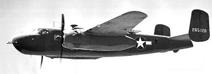
The G was the first model to carry a 75mm Army M-4 cannon in the nose. One conversion from a B-25C with new s/n, 43-32384, was completed in 1942 as the XB-25G.

North American B-25G Cannon installation

The B-25G (NA-96) of 1942 was a four-crew production model with the M-4 cannon. 405 were built; 42-64902/65201, and -64802/65201.

North American B-25G 42-65128

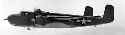
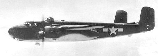
The 1943 B-25H (NA-98) increased its armament to four .50-caliber guns in an armored nose and two pairs of .50-caliber guns on each side of the fuselage. It was the precision bomber version of the H; the crew increased to six to include a bombardier.

North American B-25H

1,000 B-25H were built: 42-4105/5104.

The B-25J, built at the Kansas plant, was the most widely produced version, 4318 being produced 1943-45.

More than 700 B 25s were acquired by the U.S. Navy and Marines, as the PBJ. USN/USCG transfers of USAAF B-25 for use in mine-laying, harassing night raids, and bombing and torpedoing ships in the Southwest Pacific theatre.

The US Marine Corp operated B-25s as the PBJ-1C (1943 50 ex-B-25Cs; 34998-35047), PBJ-1D (1943 152 ex-B-25Ds; 35048-35096, 35098-35193, 35196-35202), PBJ-1G (1 ex-B-25G; 42-65031/35097), PBJ-1H (248 ex-B-25Hs; 35250-35297, 88872-89071), and PBJ-1J models (255 ex-B-25Js; 35194-35195, 35203/35249, 35798-35920, 38980-39012, 64943-64992).

North American PBJ-1H

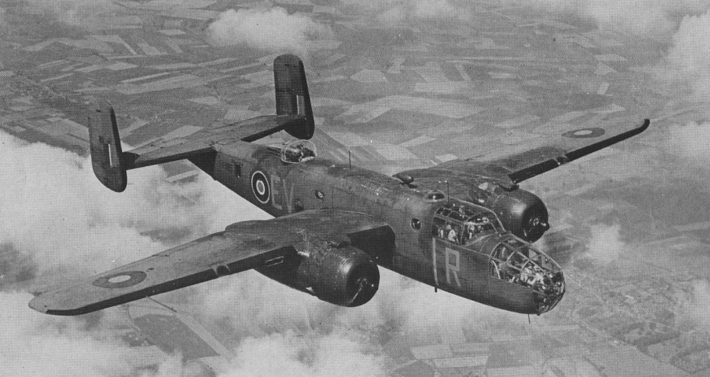
The Royal Air Force received about 800, and the airplane was flown more than a dozen other countries. Top speed only reached about 270 mph but the Mitchell’s 1,350 mile range made it very useful.

The Americans did not use Mitchells operationally from the United Kingdom but based them with the 12th United States Army Air Force in the Mediterranean. However the British, Dutch and Russians received large numbers.

Mitchell II

Training aircraft were the AT-25, later designated the TB-25.

All B-25 models were powered by Wright R-2600 Cyclone 14 engine. More than 12000 aircraft built.

In April 1942 sixteen Mitchells, operating from the American aircraft carrier USS Hornet, made one of the most daring bomber raids in the Second World War, on Tokyo.

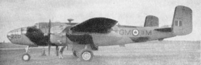
In 1955 large numbers of these wartime medium bombers were still used by the R.C.A.F. for a variety of duties. The target towing version shown here is powered by two 1,700 h.p. Wright R2600-13 engines.

B-25D

About 100 B-25Js, with glazed noses, are used for all weather crew training and guided weapon development. Other B-25Ds and Js were used by Reserve squadrons. TB-25s were in service with the U.S.A.F.

The Mitchell was used in all theatres and a total of 9816 were built, essentially unaltered in airframe and engines, but revised in armament, armour and fuel. There were 1619 B-25C built, and 1000 B-25J. A total of 9,816 were delivered to USAAF, and about 2,000 more exported to Allied air services. The USN version was the PBJ. The last, a TB-25, was finally retired from USAAF duty in Jan 1959.

Serials of North American B-25C Mitchell
B-25C
41-12434-13038 / c/n 82-5069/82-5673
B-25C-1
41-13039-13296 / c/n 82-5674/82-5931
B-25C-10
42-32233-32382 / c/n 94-12641/94-12790
B-25C-15
42-32383-32532 / c/n 93-12491/93-12640
B-25C-5
42-53332-53493 / c/n 90-11819/90-11980
B-25C-20
42-64502-64701 / c/n 96-16381/96-16580
B-25C-25
42-64702-64801 / c/n 96-16581/96-16680

Gallery

B-25
Initial model

B-25A / NA-62A
Max speed: 315 mph
Cruise speed: 262 mph
Stall: 90 mph
Range: 1350 mi
Ceiling: 27,000 ft

B-25B
Dorsal & ventral turrets

B-25C / PBJ-1C
Engines: Two Wright R-2600-13 Double Cyclone, 1700 hp takeoff, 1500 hp at 2400 rpm.
Wingspan: 67 ft 67.7 in
Length: 53 ft 0 in
Height: 15 ft 9 in
Wing area: 610 sq.ft
Empty weight: 20,300 lb
Maximum weight: 34,000 lb
Maximum speed: 284 mph at 15,000 ft.
Cruising speed: 233 mph at 15,000 ft.
Initial climb rate: 1100 fpm
Time to 15,000 ft: 16.5 min
Service ceiling: 24,000 ft
Range: 1500 miles with 3000 lb bombs.
Internal fuel capacity: 670 US gal
Ferry fuel capacity: 1255 US gal
Opt fuel later mods: 800 US gal
Armament B-25C: 4 x 0.50-inch machine guns, 1 x 0.30-inch machine gun
Armament B-25C-5: 6 x 0.50-inch machine guns
Normal bomb load: 3000 lb
Underwing bomb load B-25C-1-NA: 2200 lb
Max bomb load B-25C-1-NA: 5200 lb

B-25D Mitchell / PBJ-1D
Ventral bomb racks
Engines: two 1,700 h.p. Wright R2600-13
Span: 67 ft. 7 in
Max Weight: 33,500 lb
Max Speed: 303 m.p.h.

B-25G / PBJ-1G / NA-96
Length: 51’0″
Max speed: 281 mph
Cruise speed: 248 mph
Stall: 105 mph
Range: 1560 mi
Ceiling: 24,300 ft
Armament: 75 mm M-4 cannon
Crew: 4

B-25H / PBJ-1H / NA-98
Improved B-25G
Engines: Wright R-2600-13 Cyclone, 1700 hp / 1268 kW
Wingspan: 67 ft 7 in / 20.60 m
Length: 51 ft 0 in / 13.34 m
Height: 15 ft 9 in / 4.80 m
Wing area: 610,0 sq.ft / 56.67 sq.m
Empty weight: 19,975 lb / 9061 kg
MTOW: 36,047 lb / 16,351 kg
Max speed: 275 mph / 442 kph at 13,000 ft / 3960 m
Cruise speed: 230 mph
Stall: 105 mph
Climb to 15,000 ft / 4570 m: 19 min 0 sec
Service ceiling: 23,800 ft / 7255 m
Range: 2700 mi / 4344 km
Armament: 1 x 75mm T-13E1 cannon, 12 x .50 in mg
Bomb load: 3200 lb / 1452 kg or 1 x 2000 lb / 907 kg torpedo
Seats: 5

B-25J / PBJ-1J
Improved B-25H initially with B-25D glazed nose, later solid 8 gun nose
Engines: 2 x Wright R-2600-92 Cyclone, 1268kW / 1700 hp
Wingspan: 20.6 m / 67 ft 7 in
Length: 16.13 m / 52 ft 11 in
Height: 4.98 m / 16 ft 4 in
Wing area: 56.67 sq.m / 609.99 sq ft
Max take-off weight: 15876 kg / 35001 lb
Empty weight: 8836 kg / 19480 lb
Fuel capacity: 811 gal
Max. speed: 237 kts / 438 km/h / 272 mph at 13,000 ft
Cruising speed: 200 kts / 370 km/h
Ceiling: 7375 m / 24200 ft
Cruising altitude: 12992 ft / 3960 m
Wing load: 57.4 lb/sq.ft / 280.0 kg/sq.m
Range: 2173 km / 1350 miles with 3000 lb bombload
Armament: 12 x 12.7mm / .50 machine-guns, 1300-1800kg of bombs
Crew: 5

TB-25