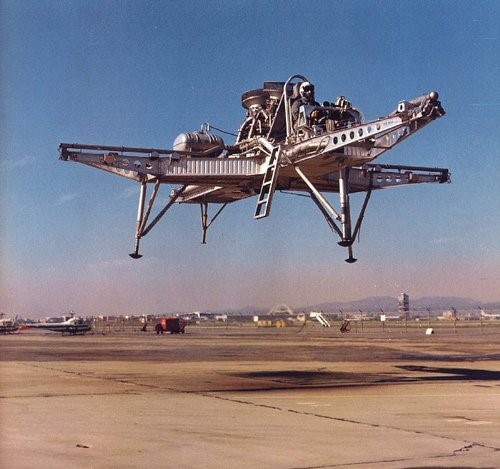
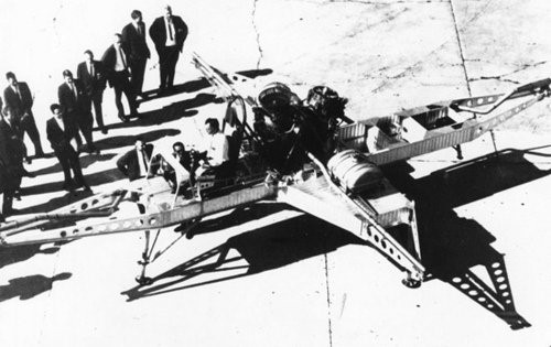
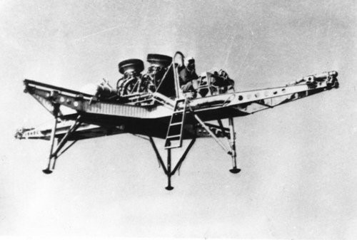
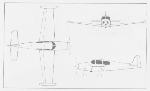
The North American FS-1 (Flight Simulator Number 1) Hoverbuggy was a 1965 open framework VTOL research vehicle with two 2200 lb GE YJ85 turbojets for lift, and four engine bleed-air nozzles on outriggers for control.
The craft had made 15 tethered and 185 free flights at altitudes up to 100ft when the program was shut down in 1967.
Engines: two x GE YJ85, 2200 lb Span: 23’0″ Length: 36’0″ Useful load: 1550 lb Max speed: 58 mph Range 10 mi
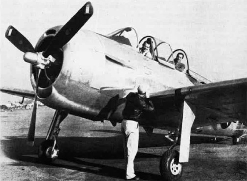
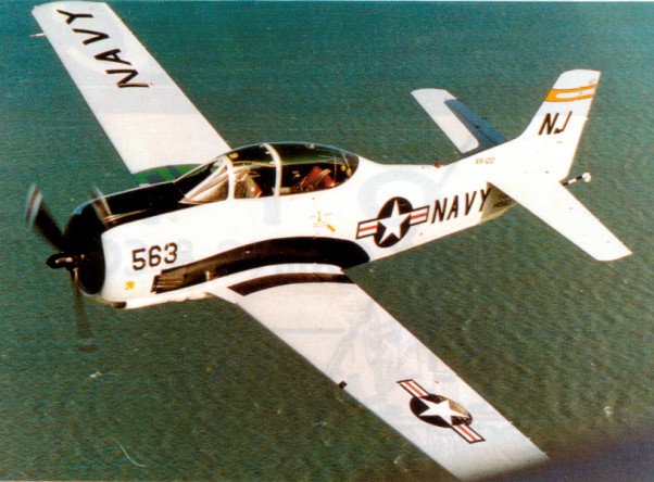
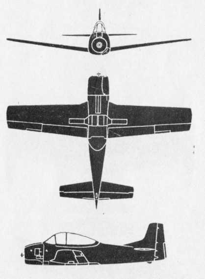
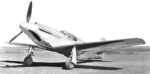
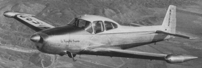
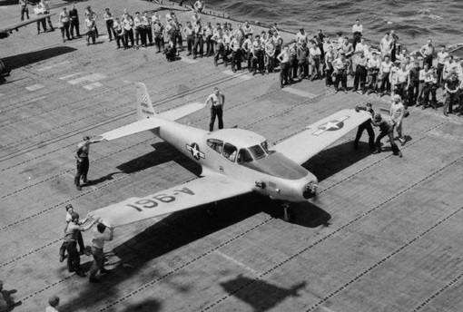
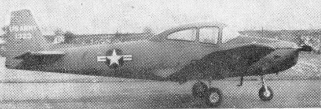
The North American XSN2J-1, also known by the company designation NA-142, was developed for the United States Navy by North American Aviation as a replacement for the SNJ Texan as an advanced scout-trainer.
Designed in competition with the Fairchild XNQ, the XSN2J-1 first flew on 15 February 1947, two aircraft being evaluated by the Navy (121449 and 121450) as XSN2J-1. Neither aircraft were considered satisfactory in evaluations; in addition, restrictions on the Navy’s budget meant that the aircraft could not be ordered at the time, and the program was cancelled in 1948.
The similar T-28 Trojan would later be ordered to fill the Navy’s requirement for a new trainer.
Clambered over an SN2J in the junk pile behind Service Test at NAS Patuxent, MD in late ’49. Nice looking bird. John W. Bradford, Jr.
Engine: 1 × Wright R-1820-78 Cyclone, 1,100 hp (820 kW) Propeller: 3-bladed Wingspan: 41 ft (12 m) Wing area: 236 sq ft (21.9 sq.m) Length: 32 ft (9.8 m) Empty weight: 5,500 lb (2,495 kg) Gross weight: 7,500 lb (3,402 kg) Maximum speed: 270 mph (435 km/h; 235 kn) Cruise speed: 190 mph (306 km/h; 165 kn) Range: 1,600 mi (1,390 nmi; 2,575 km) Service ceiling: 30,000 ft (9,100 m) service Crew: Two (student and instructor)
During and immediately following WWII, NAA developed the next generation, high performance, advanced trainer to serve as a successor to the NAA T-6/SNJ Texan. The result was the T-28 Trojan series.
First flown on 26 September 1949 as the XT 28A, the Trojan was put into production as the T-28A two-seat basic trainer for the USAF. Power was provided by a 596kW Wright R-1300-1 radial engine. 1,194 “A” models were built with the Aero Product 2-blade propeller. The Air Force used these aircraft for training and various other roles from 1950 to 1956. The “A” model also replaced the Mustang fighters in the reserve units until 1959.
Ordered into production by the USAF in 1950 as the T-28A, the US Navy evaluated the T 28A in 1952 and decided that the Wright Cyclone R1300, with 800 hp and a two bladed propellor left the aircraft under-powered for carrier operations.
In 1952, the Navy contracted with NAA to build 489 T 28Bs, an improved version. The T-28B was the initial US Navy version fitted with a 1425 hp / 1,062kW Wright R-1820-86 engine, Hamilton Standard 3-blade propeller, belly mounted speed brake, and a two-piece sliding canopy (as fitted to late production T-28A). 489 “B” models were built and used from the middle 50’s to the middle 80’s.
T-28B
The T-28C was built for the Navy starting in 1955. The T-28C is equipped with a tail hook, a smaller diameter propeller, and other minor changes to allow aircraft carrier landings. 299 “C” models were manufactured with production ending in 1957.
In 1958 many T-28As were declared surplus and North American designed a modification scheme to convert the into two-seat utility aircraft, under the name Nomad. The main change involved replacing the original 800 hp Wright R-1300 engine with the more powerful R-1820. Supplementary modifications were drawn up to convert the Nomad into a military light strike-reconnaissance aircraft.
In 1959, several hundred surplus “A” models were shipped to France and were modified with the 1,062kW R-1820-56S engine, structural improvements, and armament for combat use, by Sud Aviation for the French Air Force. Sud-Aviation were given a contract for 135 conversions of ex-USAF T-28As under licence to PacAero, who had taken over the Nomad conversion programme from North American. These aircraft are commonly referred as Fennec, T-28S (Sud), or T-28F. After success in combat in Algeria in the early sixties, they continued to serve France and several other countries for many years.
Sud-Aviation Fennec
Similar to the FENNEC but converted by various contractors in the U.S., the T-28D-5 also started as a surplus “A” model. Almost 250 “D” models were supplied to U.S. and other forces fighting in Southeast Asia. Additionally, “B” & “C” models, known as the T-28D-10, were also modified and used in combat.
During the early 1960s the United States Tactical Air Command (TAC) was directed to develop a counter-insurgency (COIN) force tailored to train friendly air forces to fight in limited wars against guerrilla forces. As a result of this directive TAC began evaluating existing aircraft types to find an available and inexpensive aircraft that could be modified for use as a COIN aircraft.
This decision resulted in the T-28D which was basically a rebuilt T-28A with a more powerful engine, six underwing hardpoints, and strengthened wings. The T-28D was powered by a 1425hp Wright Cyclone R-1820-56S nine cylinder air cooled radial engine, driving a three blade Hamilton Standard propeller. To allow the T-28D to perform in its intended role of tactical fighter-bomber, the wings were strengthened to enable the aircraft to carry a variety of under wing stores up to 4,000 pounds.
Between early 1961 to late 1969, North America received a total of thirteen production contracts covering conversion of a total of 321 T-28As to the AT-28D configuration.
By December 1963 the USAF had converted 700 T-28B’s to counter-insurgency roles.
The first T-28Ds to see action were assigned to the 4400 Combat Crew Training Squadron (CCTS). In October 1961 President Kennedy authorised deployment of a detachment from the 4400 CCTS to Vietnam under the code name Farm Gate. The detachment was to train South Vietnamese pilots in the T-28 and was authorised to fly combat missions, providing there was a South Vietnamese national in the rear cockpit.
The South Vietnamese Air Force (VNAF) found the T-28D to be well suited to their needs. The short field performance and ease of maintenance made the Trojan ideally suited for forward basing in small detachments, allowing a rapid response to enemy activities. The T-28D served with the VNAF until the increasing anti-aircraft capabilities of the Viet Cong made it necessary to replace the Trojan with a more powerful and faster fighter bomber.
Despite modifications to strengthen wings to carry up to 4000 lb bombload, at least three T-28 crashes in strikes against Viet Cong may have resulted from structural failure. This contributed to T-28 withdrawals from Vietnam.
After its withdrawal from combat in Vietnam during 1964, T-28Ds continued to serve with the USAF in Thailand until 1972. T-28Ds were assigned to the 60th Special Operations Squadron (SOS), 56th Special Operations Wing in the fighter-bomber role flying missions over Laos and Cambodia. T-28Ds were also supplied to the air forces of Thailand, Cambodia and Laos.
The T-28D proved itself in combat to be an excellent gun and bomb platform, and was able to withstand a surprising amount of battle damage. The Trojan was well liked equally by its pilots and hard working ground crews. As in all previous T-28s, maintenance crews appreciated the fact that the T-28 was rugged, easy to maintain and required very few maintenance hours per flight hour.
In 1964 William Driver of Piqua, O., claimed an altitude jump record for spot parachutists by leaving a T-28 at 33,400 ft, landing 18 ft from his target on Boulder Airport.
Many T 28Ds were operated in the Congo and Vietnam, and have equipped the Thai Air Force, with the French as the Fennec as well as with the Argentine Navy. T 28Ds served with the air forces of Bolivia, Ethiopia, Kampuchea, South Korea, Laos, Taiwan, Thailand, the United States and Zaire.
In civilian use, the T-28 continues to gain in popularity. It looks, sounds, and performs comparable to a WWII fighter at a fraction of the cost. With its two roomy cockpits, tricycle landing gear, huge flaps, and superb flying characteristics, general aviation pilots can learn how to operate this aircraft. In addition, maintenance and parts availability remains reasonable with plenty of technical support available.
With 2,450 hp Lycoming T55 turboprop, underwing attachments for 4,000 lb. of weapons, and a long range fuel tank in place of the rear crew member’s position, the YAT 28E was a conversion of the T 28 piston engined basic trainer.
In 1958 North American modified one T-28, as NA-260 Nomad, to a general-purpose prototype plane. Pacific Airmotive Corp converted surplus North American T-28 to the general-purpose Nomad in 1958.
NAA T-28A Engine: Wright R-1300-1, 7-cylinder radial, 800 hp Propeller: Aero Products 10′ 2-blade, constant speed Wing Span: 40′ 1″ (12.23 m) Length: 32 ft (9.76 m) Height: 12′ 8″ Wing area: 269.1 sq.ft / 25.0 sq.m Empty, 5,111 lb (2318 kg) Loaded weight, 7,463 lb (3642 kg) Fuel capacity: 125 USgallon G Loading: +4.5, -2 Normal cruise: 180 mph at 35 USgph Max speed, 285 mph (458 kph) at 5,800 ft (1768 m) Service ceiling: 36089 ft / 11000 m Initial climb, 2,030 fpm (10.3 m/sec) Range: 1,055 mls (1698 km) Controls: Dual
T-28B Engine: Wright Cyclone R-1820-¬86, 9-cylinder radial, 1425 hp / 1063kW Propeller: Hamilton Standard Hydromatic 3-blade, constant speed Wing Span: 40 ft 8 in (12.4m) Length: 32′ 9″ Height: 12′ 7″ Wing area: 24.90 sq.m / 268.02 sq ft Empty weight: 2914 kg / 6424 lb Normal Gross Weight: 8600 lbs. G Loading: +4.5, -2 Controls: Dual Max. speed: 552 km/h / 343 mph Ceiling: 10820 m / 35500 ft Range: 1706 km / 1060 miles Normal cruise: 235 mph at 50 Usgph Fuel capacity: 177 USgallon Endurance: 3 hr w/res Rate of climb: 3000+ fpm Crew: 2
T 28C Engine: Wright Cyclone R-1820, 9-cylinder radial, 1425 hp Propeller: Hamilton Standard Hydromatic 3-blade, constant speed Wing Span: 40 ft 8 in (12.4m) Length: 32′ 9″ Height: 12′ 7″ Normal Gross Weight: 8600 lbs. Empty weight: 6400 lb G Loading: +4.5, -2 Controls: Dual Normal cruise: 235 mph at 50 Usgph Fuel capacity: 177 USgallon Endurance: 3 hr w/res Rate of climb: 4,200 fpm Ceiling: 35,000 ft Maximum speed: 343 mph Range: 1060 miles Stall speed: 67 kts Hard points: 6
T-28D Trojan Engine: Wright R-1820-86A Cyclone 1,425hp Propeller: Hamilton Standard Hydromatic three blade constant speed Fuel: Aviation Gasoline 100 Octane Wingspan: 40′ 1″ / 12.19 m Length: 32′ 10″ / 10.0 m Wing Area: 271.2 sq. ft / 25.19 sq. m Height: 12′ 8″ / 3.86 m Empty weight: 6,251 lbs / 2.811 kg Normal Gross Weight: 8600 lbs. Armament: Up to 4,000lb (1,813kg) of external stores including gun pods Maximum Speed: 340 knots / 391 mph / 629 km/h Cruise Speed: 200 knots / 230 mph / 370 km/h BAS G Loading: +4.5, -2 Controls: Dual Normal cruise: 235 mph at 50 Usgph Fuel capacity: 177 USgallon Endurance: 3 hr w/res Rate of climb: 3000+ fpm Armament: 2 x 0.5in mg Hardpoints, wing: 6
Fennec Engine: Wright Cyclone R-1820, 9-cylinder radial, 1425 hp Propeller: Hamilton Standard Hydromatic 3-blade, constant speed Wing Span: 40 ft 8 in (12.4m) Length: 32′ 9″ Height: 12′ 7″ Wing area: 271 sq.ft Empty weight: 6615 lb Normal Gross Weight: 8600 lb MTOW: 9370 lb Fuel capacity: 177 USgallon Max speed: 340 mph at 18,000 ft Normal cruise: 235 mph at 50 USgph at 15,000 ft Endurance: 3 hr w/res Service ceiling: 36,480 ft Rate of climb: 3000+ fpmI Max range: 1180 mi Hardpoints: 2 Bombload: 4 x 300 lb G Loading: +4.5, -2 Controls: Dual
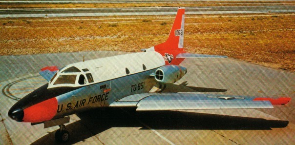
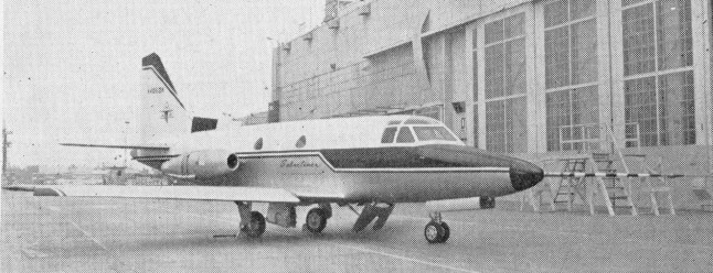
The NA-246 Sabreliner started its life as a private venture in the mid 1950s to meet the USAF’s UTX requirements for a combat readiness trainer and utility aircraft. Announced on 27 August 1956, It was laid out with a six-seat interior and to be flown by a two-man crew, the civil-registered prototype was completed in May 1958, although the lack of suitable engines delayed the first flight, which took place at Los Angeles, until 16 September, under the designation T 39. The initial powerplant comprised two 1134kg thrust General Electric YJ85 turbojets and, thus powered, the prototype completed its military evaluation programme at Edwards Air Force Base in December 1958.
In October 1958 the Sabreliner won its first order, for seven NA-265 or T-39A aircraft with 1361kg thrust Pratt & Whitney J60 engines. Production of the highly successful T 39 series commenced in 1958, and 213 were purchased by the Air Force and the Navy. All military models of the T-39 series were certificated to civil airworthiness standards, beginning with the T-39A on 23 March 1962.
The commercial version of the T 39, known as the NA-265-40 Sabreliner / Sabre 40, was type certificated on 17 April 1963 and was one of the first jets available to business aviation. It is larger and more rugged and powerful than jets that have been designed solely for civilian use. Its speed by jet standards is modest with a cruise of 489 knots. The aircraft maintained its popularity throughout the 1960s and 1970s as improvements were made to the airframe and powerplants.
In 1965 North American increased the Sabreliner’s gross weight by beefing up landing gear and re-qualifying wheels. The modification allows the twin-jet to carry full fuel with nine people and baggage aboard totalling 18,650 lb. The previous max was 17,760 lb. Changes were offered free to Sabreliner owners.
One of the unusual features that the Sabreliner was automatic leading edge slats. The slats added impressive low speed handling qualities to the bizjet.
Gone are the slats, however, from a Sabreliner 60. The stretched Sabre 60, introduced in 1969, is powered by two 3,300 pound thrust P&W JT12A 8 turbojets, the same engine that was used in the Dash 8 JetStar.
The Rockwell Sabreliner 65 is essentially a fanjet, supercritical wing version of the Sabre 60. Its engines are Garrett AiResearch TFE 731-3s, which the factory may also retrofit to Model 60s and the even earlier Sabre 40s. Its IFR range was just under 2,500 nautical miles. The first production lot of Sabre 65s was sold at an average equipped price of $3,250,000.
Both the 74 and 60 models were fitted with thrust reversers to aid in shorter landings and assist in braking on icy or wet runways.
75A
The Sabre 75A, with its expanded cabin height and higher gross weight, uses two General Elec¬tric CF700 2D2 turbofans identical to the 4,315 pound thrust powerplants employed on the Falcon 20. The 75A model features square windows, a ‘stand-up’ cabin and a long span tailplane.
In 1978 Rockwell International’s Sabreliner 80A made a first flight from St. Louis. The new business jet is a modified version of the Model 75A, with a supercritical wing.
Civil production of all models, including the final model, the Sabreliner 65A, totalled well over 600 aircraft when the last aircraft came off the line in 1981.
Rockewell International’s Sabreliner Division was acquired in 1983 by the specially formed Sabreliner Corporation of St Louis, Missouri to continue product support. Type Certificate A2WE was reissued to Saberliner Corp in 1983 to cover active Model 265s. At the end of 1990 the company completed the design of a new version of the Sabreliner designated the Model 85. This has a supercritical wing incorporating winglets, a fuselage stretch of 1.5m, and more powerful TFE731-5 turbofan engines, but further development would require a risk-sharing partner.
NA-246 Sabreliner / T-39 Engines: 2 x General Electric YJ85 turbojets 1134kg thrust
T-39 Engines: 2 x P&W Wing span: 44 ft 5 in (13.54 m) Length: 43 ft 9 in (13.34 m) Height: 16 ft 0 in (4.88 m) Max TO wt: 17,760 lb (8055 kg) Max level speed: 595 mph (958 kph)
NA 265-65 Sabreliner 65 Engines: 2 x Garrett TFE 731-3R-1D, 3700 lbs / 1678kg thrust Seats: 10 Length: 14.30 m / 46 ft 11 in Height: 4.88 m / 16 ft Wingspan: 15.37 m / 50.5 ft Wing area: 380 sq.ft Wing aspect ratio: 6.7 Maximum ramp weight: 24,000 lbs Maximum takeoff weight: 10886 kg / 24,000 lbs Standard empty weight: 13,350 lbs Maximum useful load: 10,650 lbs Zero-fuel weight: 16,250 lbs Maximum landing weight: 21,755 lbs Wing loading: 63.2 lbs/sq.ft Power loading: 3.2 lbs/lb Maximum usable fuel: 8644 lbs Best rate of climb: 3540 fpm Certificated ceiling: 13715 m / 45,000 ft Max pressurisation differential: 8.8 psi 8000 ft cabin alt @: 45,000 ft Maximum single-engine rate of climb: 950 fpm @ 127 kts Single-engine climb gradient: 452 ft/nm Single-engine ceiling: 25,000 ft Maximum speed: 513 kts Normal cruise @ 43,000ft: 430 kts Fuel flow @ normal cruise: 1090 pph Stalling speed clean: 117 kts Stalling speed gear/flaps down: 81 kts Turbulent-air penetration speed: 225 kts
Sabreliner 65A
Sabreliner 75A Engines: 2 x General Elec¬tric CF700-2D2, 4315 lb Seats: 8/10 Wing loading: 68.11 lb/sq.ft Pwr loading: 2.53 lb/lb Max TO wt: 22,800 lb Operating wt: 13,600 lb Equipped useful load: 9200 lb Payload max fuel: 1820 lb Zero fuel wt: 15,620 lb Range max fuel/cruise: 1985 nm/4.0 hr Range max fuel / range: 1897 nm/ 4.6 hr Service ceiling: 45,000 ft Max cruise: 489 kt Max range cruise: 417 kt Vmc: 92 kt Stall: 105-113 kt 1.3 Vso: 137 kt ROC: 4500 fpm SE ROC: 1050 fpm @ 190 kt SE Service ceiling: 24,000 ft Cabin press: 8.8 psi Fuel cap: 7380 lb Takeoff run (balanced) 4,420 ft Landing roll 2,525 ft
Developed to USAF General Operational Requirement 38 for an intercontinental bomber to replace the Boeing B-52.
At one time the order was cut back to a single prototype containing no military equipment. In 1960 the US Government decided to order 12 fully operational B-70s. In March 1961, the contract awarded on 4 October 1961 was again cut back to three aeroplanes, intended mainly for research, although the third was later cancelled.
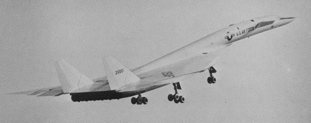
The North American XB-70 Valkyrie first flew in prototype form on 21 September 1964. When the first prototype flew it was simultaneously the longest (56.4 m/185 ft), fastest (Mach 3+), most powerful and costliest aircraft ever built, US$2000 million, and weighing 305 tonne (300 ton). Piloted by North American test pilot Alvin S. White and USAF Col. Joseph F. Cotton the first take-off took a 5000 ft ground roll and 30 seconds to get airborne. During the 65 min flight from Palmdale to Edwards Air Force Base the main wheels failed to retract and number three J93 GE engine over-revved. The aircraft flew to 16,000 ft and 375 mph. Locked rear wheels on the left main gear ground themselves down to metal on touch-down.
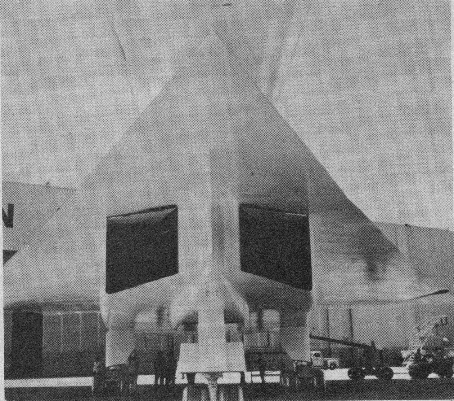
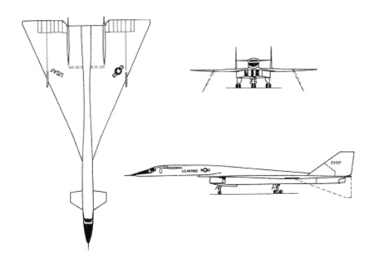
A delta-winged canard design, the airframe made extensive use of contemporary ‘exotic’ alloys to overcome the problems associated with kinetic heating. The wings were swept back at 65 degrees 34 minutes on the leading edge, and were covered with brazed stainless steel honeycomb panels welded together to produce an extremely strong yet heat-resistant whole. Similar construction was used for the huge rectangular moveable engine duct under the centreline, the twin vertical tail surfaces (30 ft high) and part of the fuselage. The advanced aerodynamics of this elegant yet menacing warplane were based on a large delta wing from whose centre grew a slim forward fuselage complete with canard foreplanes.
The powerplant comprised six 31,000-lb (14.062-kg) thrust General Electric YJ93-GE-3 afterburning turbojets in a 30 ft long ducted arrangement under virtually the full chord of the delta wing. To slow entering airstream from Mach 3 to less than Mach 1 the designers created a series of shock patterns which employ the vertical splitter, then additional breaks within the splitter duct. Finally hydraulically operated panels vary final throat area to meet varying conditions.
The wings outer portions were arranged to hinge downward in flight under hydraulic power to improve stability and maneuverability. An anhedral angle of 25 degrees was used for low-altitude supersonic flight, increasing to 65 degrees for high-altitude flight at Mach 3. Six power hinge actuators on each lower outer surfaces during high speed flight. Each hinge has hundreds of closely meshed gears of hard H-11 steel.
Control was provided by a combination of flaps on the canard foreplanes, no fewer than 12 wide-chord elevons across much of the trailing edge of the wings outboard of the variable-geometry engine exhausts, and large rudders on each of the vertical surfaces. The canard slab surfaces provide trim control while keeping drag low, their rear section deflecting down as flaps. Control of so complex an aerodynamic platform moving at high supersonic speeds was effected with the aid of a three-axis stability-augmentation system.
The landing gear consists of 2 tons of wheels, tires and brakes. A brake control device employs a fifth wheel on the main gear, comparing the amount of slippage between braked wheels and the fifth wheel with coefficient of friction between tires and runway surface, predicts skid point, and automatically regulates
The windshield moves along with a variable-position nose ramp. During subsonic operation the forward edge of the windshield can be lowered for better visibility. Dark spots above the cockpit area and on the canard surfaces are crane lift points.
The first prototype was flown by Alvin S. White and Colonel Joseph F. Cotton on 21 September 1964. The take-off from Palmdale runway required 5000 ft and less than 30 sec roll. During the flight the undercarriage failed to retract, one of the six engines failed, and a brake locked which burned out half of the left main gear supports. The flight was held to a maximum of 375 mph and 16,000 ft for the flight of just over one hour.
The first flight had been so long postponed and the entire project downgraded to only two prototypes. By the flight, the first US had spent $1.34 billion on its development. $92 million was then allocated to see the two prototypes through the flight program. Both XB-70’s were programmed for a 180 hr flight test schedule, including experiments for NASA. It first achieved its design speed of Mach 3 on 14 October 1965.
NASA’s Flight Research Center spent $2,000,000 on instrumentation on the No.1 aircraft. Areas of study included flutter of skin panels and internal noise levels; heating of structures in such areas as windshield, fuel tanks and crew compartment.
The improved second prototype flew on 17 July 1965, but was lost in a mid-air collision on 8 June 1966. The surviving aircraft carried out a number of test programmes, including work in connection with the US supersonic transport programme, but on 4 February 1969 it was flown to retirement at the US Air Force Museum, Wright Patterson AFB, Dayton, Ohio.
Even before the first prototype flew, however, technological developments in air defence had made the XB-70 obsolete. In 1963 the U.S. government ended the XB 70 development programme and turned the prototypes over for research purposes although one of the XB 70s was lost on 8 June 1966. The surviving XB 70 is now a museum piece.
Engines: 6 x General Electric YJ93-GE-3 afterburning turbojets, 31,000-lb (14.062-kg) Wing span: 105 ft 0 in (32 m) Length: 196 ft 0 in (59.74 m) Max TO wt: 530,000 lb (240,400 kg) Max level speed: M3 / 3218 km/h / 2000 mph Height: 9.1 m / 29 ft 10 in Wing area: 565.0 sq.m / 6081.60 sq ft Ceiling: 21336 m / 70000 ft Range w/max.fuel: 12000 km / 7457 miles Crew: 2
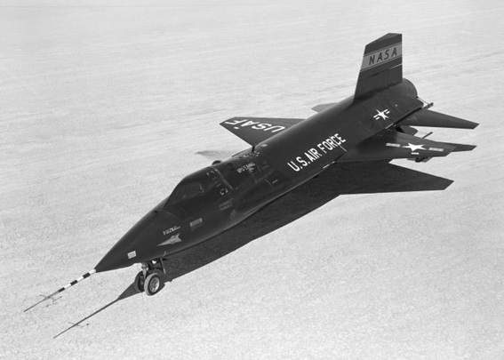
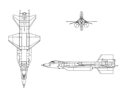
The X-15 was a hypersonic research aeroplane, a rocket-powered type air-launched by an adapted B-52 bomber within a programme that yielded important results in flight at very high speed and extreme altitudes. The objective was an aeroplane capable of flying at 4,500 mph (7,240 km/h; nearly Mach 7) and reaching an altitude of 250,000 ft (76,200 m). North American Aviation won the design contest and was awarded a development contract on 30 September 1955.
The aircraft was designated X 15 and was designed around a Thiokol (Reaction Motors) XLR99-RM-2 single-chamber throttleable XLR99 liquid-¬fuel rocket engine capable of delivering a thrust of more than 60,000 lb (27,215kg) for a period of several minutes. Like X 1, the X 15 was to be air launched, since fuel could not be expended in getting the X 15 off the ground and up to operating altitudes.
The X-15 was built largely of titanium and stainless steel, covered mostly with a so-called ‘armour skin’ of Inconel X nickel steel alloy to withstand temperatures ranging from 1200 deg F to –300 deg F, with heating rates of 30 BTU per sq ft of surface area per second. Far higher temperatures were recorded by the X-15A-2 after this type had been fitted with Emerson Electric T-500 ablative material to provide a capability for comparatively steep (and therefore high ¬friction) angles of re-entry after apogee in the interface between the troposphere and space. This capability to operate on the edges of space demanded a reaction control system for orientation of the aeroplane in these virtually airless regions: a rocket system was used for this stem, with four nozzles in the wingtips and eight more nozzles in the nose to provide three-dimensional manoeuvre capability.
Two Boeing B 52s were modified as carriers for the X 15s, three of which were ordered. With a span of only 22 ft (6.70 m) for the slightly swept¬back trapezoidal wings the X 15 had a gross weight at launch of over 31,000 lb (14,060 kg), of which more than 18,000 lb (8,165 kg) was accounted for by the liquid oxygen and anhydrous ammonia rocket propellants.
In September 1957, the first one rolled out of the factory. Six months later, in March 1959, the X-15 made its first captive flight and, three months after that, its first glide flight.
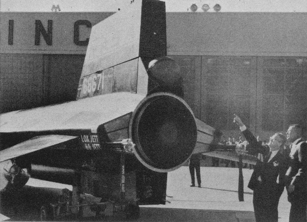
When the first X 15 free flight was made on 8 June 1959 the aircraft was fitted with lower powered engines, as the XLR99 was not then ready. Carried aloft by an NB-52, the X-15 was piloted by Scott Crossfield. With two XLR11 RM 5s, giving a combined thrust of about 33,000 lb (15,000 kg), the first powered flight was made by the second X 15 prototype (56-6671) on 17 September 1959, a speed of Mach 2.11 and altitude of 52,341 ft being achieved. From that point on, both the speed and the altitude reached by the X 15s climbed steadily, with Mach 3 being reached in November 1961 after the XLR99 engine had been fitted in the second prototype. By December 1963 the X 15s had reached a speed of Mach 6.06, had encountered a skin temperature of 1,320 degrees F and reached an altitude of 314,750 ft (95,936 m).
In June 1959, in the X-15s very first free flight, Crossfield’s landing was a little touchy due to the pitch damper failure and pilot-induced oscillation.
On 17 September 1959, Scott Crossfield took the X-15 through the paces of its first powered flight. In its second powered flight three months later, also flown by Crossfield, the vehicle’s nose gear door failed due to a rough landing on Rogers Dry Lake. According to the official report, the structural failure occurred on landing “due to design flaw and excessive propellant weight,” but the NASA engineers at Edwards knew otherwise and North American then adopted the special approach theory for landing. This involved a 360 degree spiralling descent starting at about 40,000 ft, right above the desired touchdown point on the runway. From that ‘high key’ position, the pilot moved into a 35 degree bank (usually to the left) while maintaining an airspeed of 285-345 mph. At roughly 20,000 ft after some 180 degrees of the spiral had been completed, the X-15 reached the ’low key’. At this point, the aircraft was headed in the opposite direction of the landing runway and was about four miles abeam of the touchdown point. From the low key, the turn continued through the other 180 degrees until X-15 lined up with the runway at about a five mile distance. The rate of descent through the spiral averaged over two miles per minute, which meant it took on average about three minutes to go from high key to that point where the X-15 was ready to head straight for landing.
Neil Armstrong’s second X-15 flight, and his first for research purposes, came just before noon on Friday 9 December 1960, also in the number one airplane. Flight 1-19-32 first tested the X-15’s newly installed ‘ball nose’. Until this flight, the X-15 had a front mounted boom with vanes to sense airspeed, altitude, angle of attack, and angle of sideslip in a free aerodynamic flow field. At such high altitudes and high speeds, the X-15 would melt its nose boom, destroying measurement data. The ball nose sphere could be cooled from the inside by liquid nitrogen.
Equidistant from the circumference were sensor ports in the middle of the ball as well as on the top and bottom. The ball moved automatically in pitch and yaw to keep the pressure equal on both of the ports, pointing the centre hole directly into the free flow. The angle of the ball movement amounted to the airplane’s angle of attack. Similarly, the ball nose received precise indications of angle of sideslip and dynamic pressure, which then gave airspeed.
Flight 3-4-7 piloted by Neil Armstrong on 5 April 1962, reached Mach 4.12 and 180,000 ft to test the MH96 reaction controls. The test flight spanned 181.7 miles in a little over 11 minutes before landing at Rogers Dry Lake. Flight 3-4-8, on Friday 20 April 1962, by Neil Armstrong, was to test the MH-96 system limit, or ‘g limiter’, to prevent the pilot from exceeding 5g. The flight reached 207,500 ft. Ballooning creates some control problems at the altitude and made an extended trip back. Neil Armstrong’s X-15 flight on 27 June 1962 resulted in the highest Mach number every attained in the X-15 program – Mach 5.74 or 3989 mph.
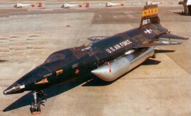
North American X-15 No.2, damaged in November 1962 in a hard landing at Mud Lake, Nevada, was completely rebuilt, ready to fly in May 1964. Most noticeable difference in X-15-2 from other models is the addition of two 22 ft fuel tanks of 38in diameter on the lower sides of the fuselage. Carrying liquid hydrogen and anhydrous ammonia, they extend burning time of the Thiokol 58,000 lb thrust YLR-99 rocket engine from 88 seconds to 146 seconds. With additional length of powered flight X-15-2 should top previous marks of 4104 mph and 354,200 ft altitude. Both set by NASA Chief Test Pilot Joe Walker.
The tanks drop off when the plane reaches Mach 2, are recoverable by parachute. Extra fuel, weighing 13,500 lb, plus other modifications, bring X-15-2’s take-off weight to 25 ton, eight ton more than the others.
The outer half of the right wing is detachable so that various structural material can be tested in flight. The plane will carry a ramjet engine slung from the tail to test hypersonic airbreathing propulsion. Liquid hydrogen ramjet fuel is stored in two internal tanks.
Cameras have been installed for ultra-violet star photography at altitude above 40 miles, beyond the ozone layer which filters out most ultra-violet rays.
The fuselage is 29in longer than other X-15’s, nose and main landing gear has been lengthened to 39.5in ground clearance, oval windshields installed to withstand higher temperatures, and ablative material added to skin surfaces to suppress heating of the basic structure.
Projects to be performed by all three X-15’s were expected to require another 100 flights running well into 1968.
The X-15A-2 propulsion system is Thiokol Chemical’s Reaction Motors Division’s YLR99 rocket engine. Even its 58,000 lb thrust can be upped through externally-mounted ramjet engines. The YLR99 operates on liquid oxygen and anhydrous ammonia which is fed into the thrust chamber by a turbopump driven by hydrogen peroxide. The ball above the engine exhaust chamber (tail slot) will contain pressurised helium which will be used to expel liquid hydrogen fuel in testing of the ramjet engines.
X-15A-2
In an experiment in 1964, an X-15 attempted a photo mission from 100,000 ft while speeding at 3290 mph over Edwards AFB (Calif). The purpose was to determine effect on camera and film of extremely high temperatures encountered at that speed, and clarity of photos for reconnaissance use.
With Major William J. “Pete” Knight at the controls, the modified X-15A-2 set an unofficial speed record of 4,520 mph (Mach 6.70) on 3 October 1967. This would be the fastest flight of the X-15 program.
X-15A-2
Before the end of 1961, the X-15 had attained its Mach 6 design goal and flown well above 200,000 feet; by the end of 1962 the X-15 was routinely flying above 300,000 feet. The X-15 had already extended the range of winged aircraft flight speeds from Mach 3.2 to Mach 6.04, the latter achieved by Bob White on 9 November 1961.
On 9 November 1962, the second X-15 crashed while executing an emergency landing on Mud Lake near Edwards AFB. Pilot Jack McKay was seriously injured but later returned to flight status. The X-15 itself was nearly a write-off, but eventually the Air Force and NASA decided to rebuild it to a slightly different configuration. The fuselage was lengthened 29 inches and external drop tanks were added to accommodate additional propellants. It was hoped this would allow the X-15A-2 to achieve at least Mach 7 while testing experimental scramjet engines. This first flew on 28 June 1964. On 22 August 1963 Joseph A. Walker, NASA test pilot, took the o.3 X-15 for a world altitude record of 351,000 ft. It was the fifth flight into space for the plane and the third for Walker. He covered 315 miles in 10 minutes. Walker released a 30-inch balloon from the plane’s tail then towed it 100 yards behind to measure air density in space. The aircraft reached a speed of 3614 mph and a climb angle of 48 degrees, the steepest yet. It used 18,000 lb of fuel in 83 seconds. Walker and the X-15 then held the world speed record of 4104 mph for winged aircraft.
In 1965 Joe Engle flew an X-15 to 78,000 ft and 3511 mph on an 8 min flight to simulate surface heating characteristics. A sheet of brown silicon rubber glued on the lower tail was expected to reduce temperature at that point from 800deg to 400 deg F.
Using an ablative coating to provide additional heat protection, Major Pete Knight took the X-15A-2 to Mach 6.72 (4,520 mph) and an altitude of 354,200 ft / 107,960m on 3 October 1967, the fastest piloted flight of the X-Plane program. This is the highest recorded speed yet achieved by man in an aeroplane capable of being controlled in normal flight. Due to damage resulting from this flight, the aircraft was retired and subsequently transferred to the Air Force Museum.
The aircraft proved remarkably flexible as a research tool. In fact, most of the later flights used the X-15 as a carrier vehicle for other experiments rather than as a research aircraft in its own right. An assortment of experiments were carried, including micrometeorite collection pods, missile detection systems, samples of insulation destined for the Saturn launch vehicle, and a wide variety of others.
After 177 flights (some report 199), the last on 24 October 1968, the X-15 programme was terminated in 1968. Of the three X-15s manufactured, one crashed while returning from space, killing test pilot Major Michael J. Adams, and one survives in the National Air and Space Museum.
Crossfield flew the X-15 a total of 13 times before North American turned it over to NASA-Air Force-Navy partnership. Two of Crossfield’s flights were in the number one airplane, the rest in number two. The highest speed he reached in any of them was Mach 2.9, the highest altitude 88.116 ft, and the furthest distance was 114.4 miles.
The NASA and other pilots were Joe Walker, Jack McKay, Robert White USAF, Neil Armstrong USN, Cmdr Forrest Petersen USN.
Engine: 1 x Reaction Motors XLR-99 rocket engine, 253.7kN Max take-off weight: 15422 kg / 34000 lb Wingspan: 6.7 m / 22 ft 0 in Length: 15.8 m / 51 ft 10 in Height: 4.1 m / 13 ft 5 in Wing area: 18.6 sq.m / 200.21 sq ft Max. speed: 7297 km/h / 4534 mph Ceiling: 107960 m / 354200 ft Crew: 1
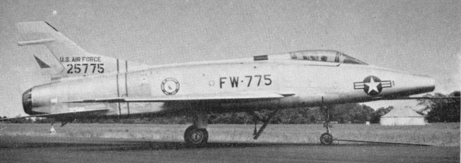
First of the “Century fighters”, the prototype F-100 flew on 25 May 1953 piloted by George Welch. Powered by a Pratt & WhitneyJ57 turbojet and augmented by an after¬burner, it flew faster than sound on its maiden flight.
Originally known as the “Sabre 45”, because of its 45-degree swept wing, the F-100 is a completely new design and was the first U.S.A.F. operational aircraft to fly supersonic in level flight. In very large-scale production as standard U.S.A.F. day fighter in 1955. Established World Speed Record of 755.15 mph on 29 October 1953.
The whole F-100 structure is immensely strong and rigid; so much so that assembly jigs are rendered unnecessary, the parts being simply put together. The wing interior is largely taken up by huge forgings, machined into honeycombs or grids; some of the outer skins are machined from sheet of no less than 3in original thickness. There was talk of the aircraft being made by Commonwealth (Australia) and Canadair.
The F-100 has an all-moving tailplane and inset ailerons, each in two sections, and automatic leading-edge slats. Ailerons were located inboard and flaps were omitted. Flaps were on the F-100D and F only. An air-brake is under the centre fuselage. The tricycle undercarriage has single wheels on each main unit ad twin wheels on the nose unit. The mains retract inward into the fuselage and nose wheels retract rearward.
The initial production version was the F-100A, a single-seat day fighter powered by a 43.15kN J57-P-7 or P-39 engine. Armament comprised four 20mm M-39E cannon plus external stores on six under-wing hardpoints.
F-100A Super Sabre
By May 1954, the U.S.A.F. had accepted delivery of a fair number of F-100As, but some had already been damaged or written-off in accidents. The F-100A was grounded in November 1954 because of transonic control problems. The height of the rudder had been reduced by some 18in and a corresponding amount added to the fin. The F-100 lands at nearly 180 mph. There are no landing flaps, but the ventral airbrake can be used on the approach.
North American F-100A Super Sabre
The F-100A production model first flew on 29 October 1951. 203 of the F-100A and RF-100A were built, the last 35 having an 11,700 lb thrust J57-P. The RF-100A was a photo-reconnaissance conversion of the F-100A with a deeper camera-carrying front fuselage.
RF-100A 53-2600
The 1956 F-100B designation was not applied as it was extensively redesigned as the F-107.
The F-100C (NA-214, -217, -222) appeared as a single-seat fighter bomber with strengthened wings, up to 3,402kg of bombs on eight underwing hardpoints, in-flight refuelling capability and 75.62kN (with afterburning) Pratt & Whitney J57-P-21A turbojet engine. First flown on 17 Jnuary 1955, 476 were built. An F-100C set the first world speed record to exceed Mach 1 on 20 August 1955 at 822.135mph.
The TF-100C of 1956 was a planned two-place trainer version modified from F-100C 54-1960, which instead became a prototype for the F-100F. Only the one was built.
TF-100C 54-1960
The similar F-100D (NA-223, -224, -235, -245) introduced design refinements, including a taller fin, landing flaps; supersonic autopilot, low-level bombing system, and could be armed with four Sidewinder or two Bullpup missiles, or 3,402kg of external weapons in addition to its standard four 20mm cannon.
F-100D 55-2851
First flown on 24 January 1956, 1274 F-100D were built.
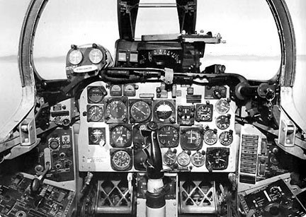
F-100D cockpit
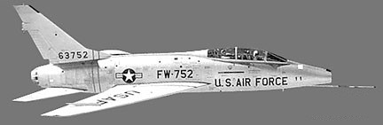
The final version built was the F-100F (NA-234, -255, -261, -262), first flown on 1 March 1957. It was a lengthened tandem two-seat operational trainer and tactical attack aircraft, armed with two 20mm cannon and capable of carrying 2,722kg of external stores. A total of 339 were built.
F-100F 56-3752
Operation Julius Caesar, involving the first flight by jet fighter aircraft over the North Pole, was conducted on 7 August 1959 with the landing of two USAF F-100F fighters at Eielson, Alaska AFB, southeast of Fairbanks, Alaska. The flight from Wethersfield, Essex, was completed in 9 hr 37 min.
Total production was 2294 aircraft when the line closed in October 1959.
After cancelling all airshows for two big summer months the Airforce Thunderbirds reverted back into F-100s in August 1965 to complete the season. They had started in Republic F-105s but a series of accidents throughout the Air Force grounded all Thunderchiefs.
F-100 Engine: 1 x P+W J-57-P-21 turbo-jet, 66.7kN Max take-off weight: 12700 kg / 27999 lb Empty weight: 9500 kg / 20944 lb Wingspan: 11.6 m / 38 ft 1 in Length: 14.3 m / 46 ft 11 in Height: 4.9 m / 16 ft 1 in Wing area: 35.8 sq.m / 385.35 sq ft Max. speed: 1216 km/h / 756 mph Ceiling: 15250 m / 50050 ft Range: 920 km / 572 miles Armament: 4 x 20mm machine-guns, 2720kg of bombs and missiles Crew: 1
North American F 100 Super Sabre Engine: Pratt & Whitney J-57-P-21A, 75645 N Length: 46.982 ft / 14.32 m Height: 14.665 ft / 4.47 m Wingspan: 38.747 ft / 11.81 m Max take off weight: 34839.0 lb / 15800.0 kg Max. speed: 751 kt / 1390 km/h Service ceiling: 45013 ft / 13720 m Range: 1304 nm / 2415 km Crew: 1 Armament: 4 mg. 3402 kg bombs
F-100A Super Sabre Engine: 10,000 lb. thrust Pratt & Whitney J57-P-7 turbojet, with afterburner. Wingspan: 36 ft. 7 in Length: 45 ft. 3 in Loaded weight: approx. 27,000 lb. Max. speed: over 760 m.p.h. Ceiling: over 50,000 ft. Range: over 1,000 miles. Armament: 4×20 mm cannon, Crew: 1.
F-100C Engine: Pratt & Whitney J57-P-21A, 16,950 lb w/afterburner Wingspan: 38 ft 9.25 in Wing area: 385.2 sq.ft Length: 54 ft 3 in Height: 16 ft 2.25 in Wheel track: 12 ft Fuel capacity: 987 Imp.Gal External fuel: 2 x 208 Imp.Gal + 2 x 187 Imp.Gal Armament: 4 x 20mm cannon Hardpoints: 6 External load: 6000 lb
F-100D Engine: Pratt & Whitney J57-P-21A afterburning turbojet, 17,000 lb / 7711 kg Wingspan: 38’10” / 11.82 m Wing area: 385.0 sq.ft / 35.77 sq.m Length: 47’2″ / 14.36 m Height: 16 ft 3 in / 4.95 m Wheel track: 12 ft Empty weight: 21,000 lb / 9525 kg MTOW: 34,832 lb / 15,800 kg Fuel capacity: 987 Imp.Gal External fuel: 2 x 208 Imp.Gal + 2 x 187 Imp.Gal Max speed: 864 mph / 1390 kph / M1.3 at 35,000 ft / 10,670 m Cruise speed: 565 mph Initial ROC: 16,000 fpm / 4877 m/min Range: 600 mi / 966 km Service ceiling: 46,000 ft / 14,020 m Armament: 4 x 20 mm cannon Hardpoints: 6 Bombload: 7500 lb / 3402 kg
F-100F Engine: Pratt & Whitney J57-P-21A, 16,950 lb w/afterburner Wingspan: 38 ft 9.25 in Wing area: 385.2 sq.ft Length: 57 ft 3 in Height: 16 ft 2.25 in Wheel track: 12 ft Fuel capacity: 987 Imp.Gal External fuel: 2 x 208 Imp.Gal + 2 x 187 Imp.Gal Armament: 2 x 20mm cannon Hardpoints: 6 External load: 7500 lb Seats: 2
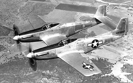
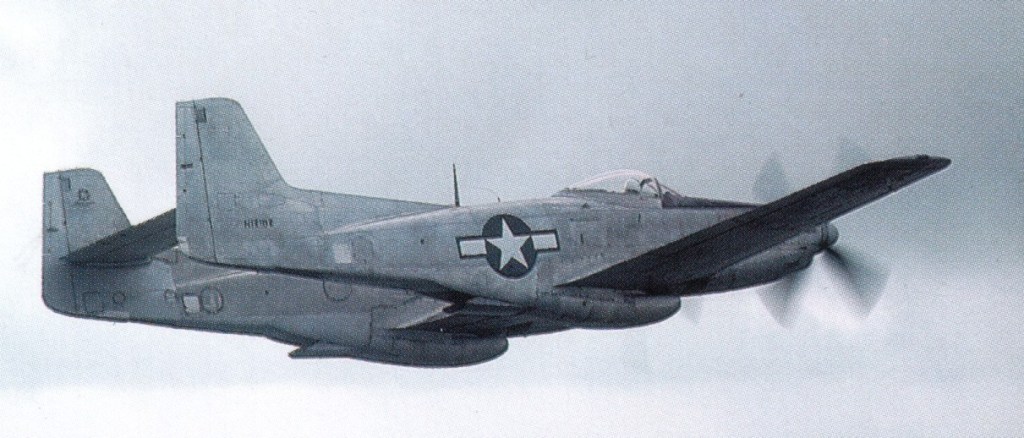
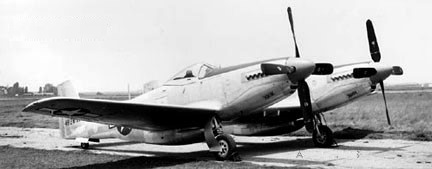
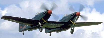
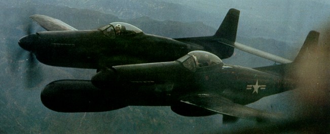
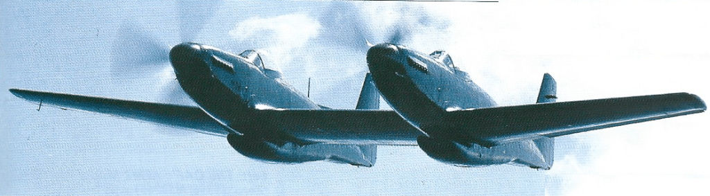
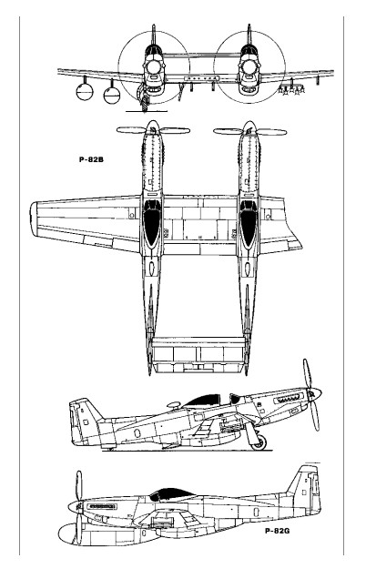
The long-range, high-altitude escort fighter, development of the P-51 Mustang, the Twin Mustang was formed by two fuselages joined by the wing and the horizontal stabilizer. The P-82 was a separate new design, not just a mating of P-51s, as commonly assumed. It was also the last prop-driven fighter to be ordered into production by USAF.
Two XP-82 (NA-120) prototypes were built (44-83886/83887) in 1945 powered by Packard-Merlin V-1650-23/25 with opposite rotating props. First flying at XP-82A on 15 April 1945.
With a pilot in each fuselage, it reduced the problem of pilot fatigue on ultra-long-range missions.
North American XP-82A 44-83888
One XP-82A (NA-120), 44-838881945, was built with Allison V-1710-119 engines.
The P-82B (NA-123) of 1945 was the initial production version. Twenty were built, 44-65160-65179.
North American P-82B
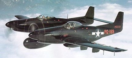
North American P-82C 44-65169
The NA-123 P-82C and -82D of 1946 were night fighter conversions of P-82Bs with a centre-section APS-4 radar pod.
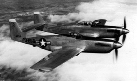
North American P-82E 46-258
100 (46-255/354) of the P-82E / NA-144 escort fighter were built in 1946.
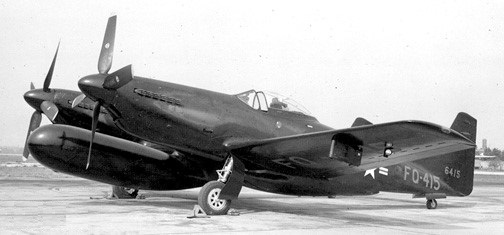
North American P-82F 46-415
The P-82F (NA-149) and G models carried a radar operator in the right cockpit instead of a co-pilot. 100 P-82F (46-405/495) night fighter were built in 1946. 45 P-82G / NA-150 (46-355/383, -389-404) all-weather night fighter with tracking radar were built in 1946, powered by Allison V-1710-143.
An F-82G was credited with downing the first enemy aircraft in the Korean War (p: Lt William Hudson), on 27 June 1950.
F-82G
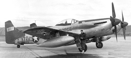
The P-82H of 1947 were Alaskan winterized conversions. Five were built from F-82F [46-384/388] and nine from F-82G [46-496/504].
North American P-82H 46-377
Re-designated F-82 in June 1948.
Although a few initial models had Merlin engines, the great majority were Allison powered and saw service in Korea.
P-82B. One of 20 initial production variants out of 500 ordered. Serialled 44-65162, restored as N12102
272 were built, the final delivery, an F-82G, in April 1949.
XP-82 / NA-120 Engines: 2 x Packard-Merlin V-1650-23/25 Props: Contra-rotating No built: 2 [44-83886/83887]
XP-82A / NA-120 1945 Engines: Allison V-1710-119 1 built 44-83888
F-82 Engine: 2 x Allison V-1710-143/145, 2300 hp Wingspan: 51 ft 3 in / 15.61 m Height: 13 ft 10 in / 4.2 m Armament: 6 x .50 mg Bombload: 2 x 4000 lb
P-82B / NA-123
P-82C / NA-123 1946 Night fighter conversions of P-82B with centre-section APS-4 radar pod. 1 built 44-65169
P-82D / NA-123 1946 Night fighter conversions of P-82B with centre-section APS-4 radar pod. 1 built 44-65170
P-82E / NA-144 1946 Escort fighter 100 built 46-255-354 Length: 39 ft 1 in / 11.88 m Height: 13 ft 10 in / 4.2 m Empty weight: 14,350 lb / 6509 kg Max loaded weight: 24,864 lb / 11,276 kg Max speed: 465 mph / 750 kph Range: 2504 mi Armament: 6 x .50 mg Bombload: 2 x 4000 lb
P-82F / NA-149 1946 Night fighter 100 built 46-405/495
P-82G / NA-150 Engine: 2 x Allison V-1710-143/145, 1600hp / 1193kW Wingspan: 15.62 m / 51 ft 3 in Length: 12.93 m / 42 ft 5 in Height: 4.22 m / 13 ft 10 in Wing area: 37.90 sq.m / 407.95 sq ft Max take-off weight: 11608 kg / 25591 lb Empty weight: 7256 kg / 15997 lb Useful load: 9594 lb Max. speed: 401 kt / 742 km/h / 461 mph Cruise speed: 285-300 mph Ceiling: 11855 m / 38900 ft Range w/max.fuel: 3605 km / 2240 miles Armament: 6 x 12.7mm machine-guns, 4x 454kg of bombs Crew: 2 45 built (46-355/383, -389-404)
Early in 1940 J.H.Kindelberger, president of North American Aviation, and J.L.Atwood, executive vice-president of the company, were called into conference with the British Purchasing Commission in New York. The British requested they build the Curtiss P-40. Kindelberger suggested they could build a better airplane, and faster. The ‘go ahead’ was given.
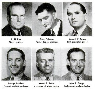
Kindelberger and Atwood conferred with Ray H. Rice, then chief engineer; Edgar Schmued, design engineer; E.J.Horkey, aerodynamicist, and others. The first conferences started on 5 April 1940 with Ken Bowen serving as project engineer. Others soon became involved.
Rice ordered a low-drag, high-lift wing. Horkey had what was then considered a radical idea on airfoils and went to work with his assistants.
The prototype was not built from production drawings but design layouts, so fast was the work done. It was ready to fly and awaiting the installation of its 1150 hp Allison engine just 100 days from the time the first drawings were made.
A month before the first flight, design for production was started. In September, Bowen was assigned the job of production engineer, assisted by George Gehrkens.
With certain unorthodox designs involving compound curves, flush shin joints for absolute smoothness, the job of tooling up for thousands of planes fabricated by unskilled workers became a problem.
As no production drawings had been made it became necessary for more than 100 men to devote themselves to this job. Each part had to be considered for re-design or simplification to make it adaptable to mass production methods. Those used in production of T-6 and B-25 were brought in. In all, 2990 design drawings were made. Others were used in making flight tests and wind tunnel tests.
Lieut.Gen. James Dolittle would call in and try out the experimental model. Immediately the throttle was moved closer to the pilot’s seat to make operation easier for short arms.
North American NA-73X NX19998
North American had designed and built the NA-73X prototype in 102 days. Late delivery of the Allison V-1710 engine delayed the first flight for another 20 days.
First flying on 26 October 1940, piloted by Vance Breese. Flights of the prototype revealed the need for many changes. Wind tunnel tests conducted by Horkey at California Institute of Technology revealed the need for more changes. For instance, flight tests showed that the air scoop intake had to be lowered to increase and alter air flow. Wind tunnel tests revealed to need to raise the carburettor air intake. A combination of tests showed that 50 pounds could be whittled off the flaps without any loss in aerodynamic efficiency. Flight test disclosed that a change in windshield design was in order.
NAA hired Vance Breeze to make the first three test flights. Then NAA test pilot Paul Balfour took over. He selected and empty fuel tank, resulting in a forced landing.
NA-73X prototype
Nine months after design for production was started the first production airplane rolled off the line. The X-73 had been built in accordance with United States Army specifications but without Army supervision, as the contract was with the British.
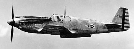
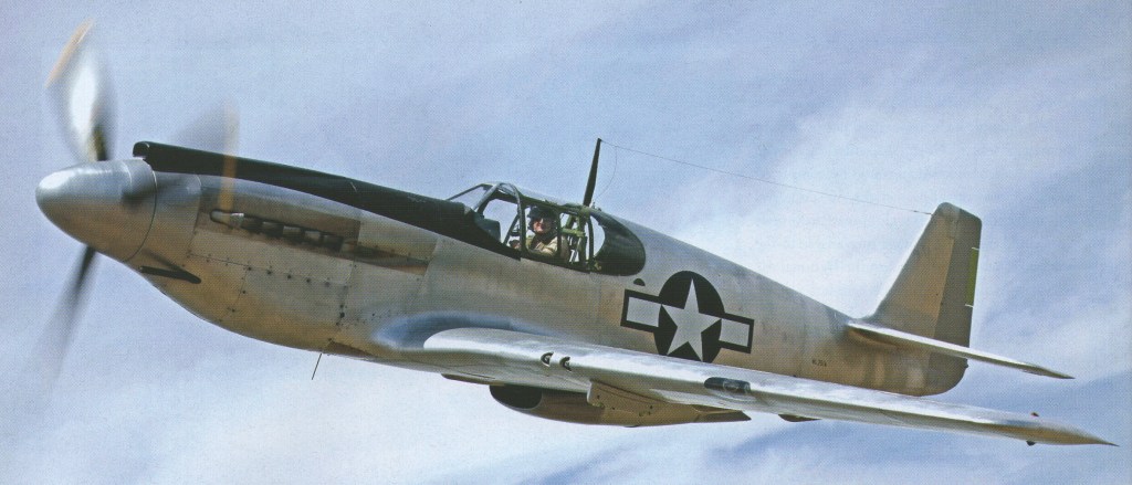
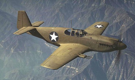
The first production NA-73 RAF Mustang I flew on 1 May 1941 and was delivered to the British in October 1941. The fifth and tenth off the production line went to the United States Army (41-038/039 for testing and experimentation. The next 150 were known as P-51’s.
Fitted with the same Allison V-1710 engine as the P 40, the Mustang proved to be a useful close support fighter and tactical reconnaissance aircraft. The aeroplane was soon ordered by the British and Americans as the Mustang and P-51 respectively.
North American XP-51 41-039
In June 1942 engineering on the A-36 began. It was equipped with dive brakes, bomb racks and six .50 calibre machine guns. It was found that it could dive and climb almost vertically, powered by a 1350 hp Allison. The A-36 order was the first from the United States Army. The first was tested in September 1942 and production was completed by March 1943.
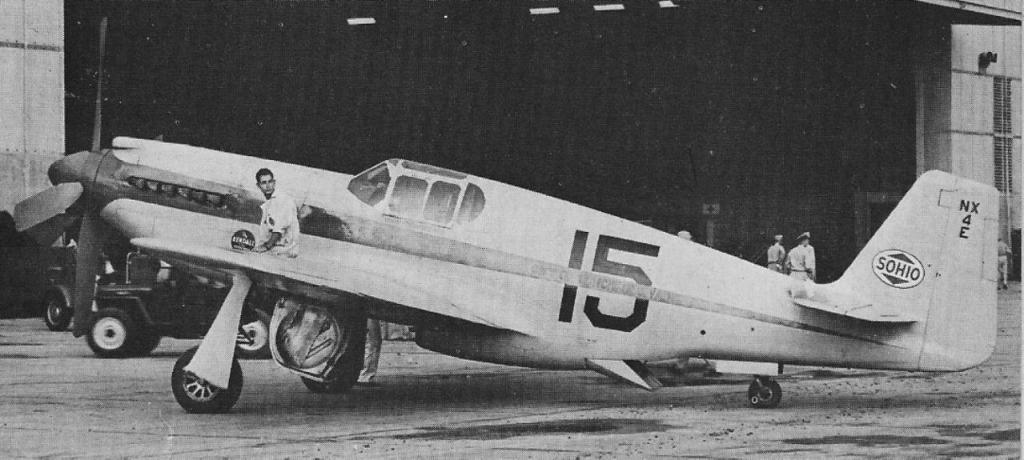
A-36 NX-4E owner/pilot Woody Edmundson, 1947 3rd in Kendall Trophy Race at 372.392mph Destroyed in non-fatal crash during Thompson Trophy Race
Two Mustangs sank an Italian cruiser and another sank an Italian transport which had been one of the world’s greatest luxury liners.
In 1941 one hundred and forty eight P-51 NA-91 (41-37320-37351, 41-37353-37420, 41-37422-374690 were built, of which 2 became test beds for Packard V-1650 as XP-51B (XP-78), and of which many early models became A-36A, plus 650 NA-73/NA-83 for RAF as Mustang I/IA (many were converted in England to Rolls-Royce Merlin).
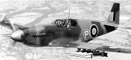
North American Mustang I
The design showed promise and AAF purchases of Allison-powered Mustangs began in 1941 primarily for photo recon and ground support use due to its limited high-altitude performance. A total of 310 P 51As were built. The 1942 P-51-1 armed recon adaptation with four wing cannon and two K-24 cameras was briefly designated F-6A at first, the unique final designation signified a batch of 57 withdrawn from an RAF Mustang I contract for USAAF duty. Fifty P 51As were allocated to the RAF as Mustang Mk IIs, while 35 were converted to F 6B tactical reconnaissance planes. Top speed was 390 mph.
P-51A
The initial P-51 and P-51A variants proved only moderately successful but in 1942, tests of P-51s using the British Rolls-Royce “Merlin” engine revealed much improved speed and service ceiling.
After some Allisom-powered P-51A were built, the Rolls-Royce Merlin, developing 1650 hp and equipped with two-stage, two-speed supercharger with a critical altitude of better than 30,000 ft, was in production and available to North American. The P-51B emerged with the Merlin and a four-blade propeller, the conversion first flying on 13 October 1942. It went into production in the late spring of 1943 with the first production aircraft flying in December 1942. The P-51B carried four .50 calibre machine guns and bomb racks. Dive brakes were eliminated. The radiator installation was redesigned and bubble canopy fitted. The plane was strengthened to carry the larger engine. New ailerons gave improved performance. The plane was cleaned up from spinner to rudder.
Wind tunnel model tests new tail fairing
Changes were being made daily, even while the planes flowed from the final assembly. Improved manufacturing methods resulted in each unit being produced with only 3300 man-hours.
P-51B
The first P-51B’s were delivered to a combat group early in November 1943. Seventeen days later, on 1 December, they conducted their first operation over enemy territory. Early in January, the group knocked down 18 German combat planes without a single loss, which was a record. A week later, the group accounted for 15 aircraft without loss. They netted a total of 103 German aircraft 83 days after starting operations, beating the Thunderbolt record of 100 planes in 85 days.
The P-51C was built in the newly constructed North American factory in Dallas, Texas, and was essentially the same as the P-51B.
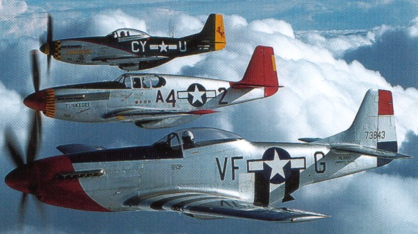
In 1943 a bubble canopy was adopted for the P¬51D, which became the main version of the famous fighter and entered combat over Europe in March 1944.
The aircraft is stressed for aerobatics and is capable of most all maneuvers with the exception of sustained inverted flight, snap rolls, outside loops, and inverted spins.
There are a number of variables regarding engines. The basic engine is the Packard built V-1650-7. The V-1650-9 was also used and is interchangeable. This V-12 engine is designed with 2 removable Cylinder bank assemblies of 6 cylinders each. These are referred to as head and banks. There are a number of engines that have been fitted with the” Transport Heads.” “Transport Heads” refer to British built assemblies that were used on a commercial aircraft engine and were designed for long life.
The basic V-1650-7 engine lower end will have a TBO in civil use of about 600 hours. The V-1650-7 heads and banks will probably require some rework at about 300 hours. The transport heads will normally last to TBO and beyond.
The P-51D holds 184 US gallons. The military used drop tanks of a maximum capacity of 110 gallons each and had a 85 gallon rear fuselage tank. Most civil operators do not use drop tanks and have a rear jump seat in place of the fuselage tank. With a normal cruise fuel burn of 65 GPH, this gives a 2 2 hour endurance with a small reserve.
A steerable type system uses an interconnect from the rudder pedals to the tailwheel steering system. This allows the pilot to steer the aircraft by use of the rudder pedals. Full forward stick movement unlocks this system. When unlocked the tailwheel becomes full swivel and steering is accomplished by differential braking.
The aircraft uses a low-pressure 1000 psi hydraulic system. The pressure is controlled and maintained by a regulator. The pilot simply operates the flaps or the gear and it works automatically. The wheel brakes are non-boosted, hydraulically actuated from individual master cylinders. The aircraft use standard MIL-5060 (red) fluid.
The aircraft has a 24 Volt D.C. system with a 100-amp generator. Some aircraft have an alternator installed. Normal aircraft have no AC electrical devices installed. A standard battery is used to provide starting and back up power. The aircraft does not require a ground power cart for normal use.
The definitive P-51D variant amounted to 7,966 of the 15,469 Mustangs. Unit cost in 1945 $50,985.
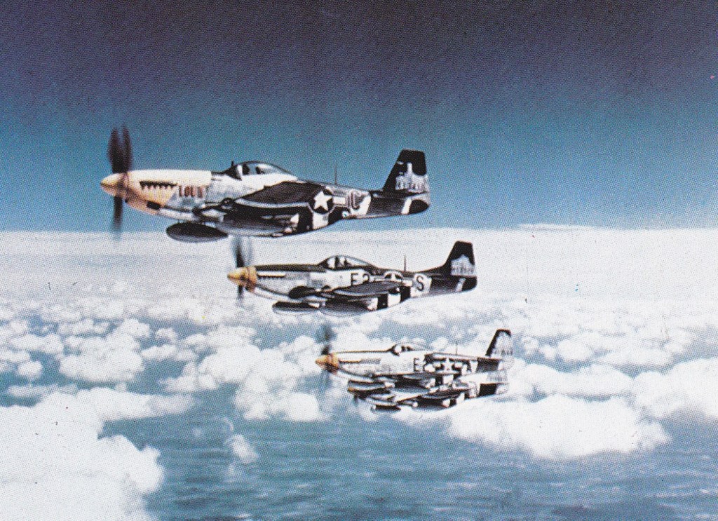
Four P-51D of the 8th Army Air Force’s 361st Fighter
The only AD on the P-51 is 81-13-01. The AD calls for inspection of the Hamilton Standard prop for corrosion. This AD starts out with an 18 month inspection interval and the interval lengthens to 60 months as the prop builds a history.
The RNZAF received 30 P-51Ds as NZ2401 to NZ2430 in late 1945 of what would have been 370 replacements for Corsairs. War’s end led to the cancellation of the remainder. The RNZAF operated P-51D until 1957.
Providing high-altitude escort to B-17s and B-24s, they scored heavily over German interceptors and by war’s end, P-51s had destroyed 4,950 enemy aircraft in the air, more than any other fighter in Europe.
Mustangs served in nearly every combat zone, including the Pacific where they escorted B-29s to Japan from Iwo Jima. Between 1941-5, the AAF ordered 14,855 Mustangs (including A-36A dive bomber and F-6 photo recon versions), of which 7,956 were P-51Ds.
On 4 October 1944 the US 8th Air Force Headquarters announced that for several days the German Luftwaffe had been using allied Mosquito and Mustang aircraft furnished with German national emblems. On 3 October 1944 a Mosquito flown by Germans was shot down near Aachen. Aerial combats had taken place over Holland between allied and German Mustang fighters. These machines in German hands were aircraft which had been forced to land behind German lines.
A-36 Apache
The final delivery, a P-51H, was made in November 1945. A total of 15386 aircraft were built including 500 A-36As and 120 P-51Ds assembled in Australia (CAC CA-17). 620 were exported to the RAF for a total to the USAAF/USAF of 14,365.
During the Korean War, P-51Ds were used primarily for close support of ground forces until withdrawn from combat in 1953.
The U.S. Military and the Royal Canadian Air Force made the largest surplus release of these aircraft in the late 50’s and early 60’s. A number of aircraft previously served with the forces of over seas countries. The aircraft sold as surplus in 1958 for prices ranging from $800-1500. The Mustang is probably the most recognized fighter of World War II and has proven to be a popular and widely used civilian Warbird.
Many people refer to the “Cavalier” Mustang as the ultimate conversion for civilian use. This conversion was performed by Trans Florida Aviation of Sarasota in the mid 60’s to the early 70’s. While this conversion was very nice at that time, most restorations done in the last 10-15 years are of superior quality. The Executive Mustang, or Cavalier, rebuild and conversion involved plush, soundproofed cockpit, IFR electronics, baggage compartments in former gun bays, 402-gal fuel tanks, and zero-time majored 1500hp Packard-Merlin V-1650-7 engine.
Successor to Trans-Florida Aviation, acquired during 1960s type certificate for North American F-51 Mustang, producing tandem two-seat business/sport conversions of F-51D as Cavalier 2000 series, and building new single-seat F-51Ds for the USAF counterinsurgency Military Assistance Program. Prototype of Mustang II, two-seat COIN patrol/attack version equipped with heavier armament, flew December 1967; prototype Turbo Mustang III (with Rolls-Royce Dart) in 1969. Second prototype flew in April 1971, equipped with Lycoming T55 engine, by which time the program had been sold to the Piper Aircraft Corporation, but then the company was dissolved.
Priced at $32,500 less radio 19 were reportedly under way by the end of 1959 (44-11558=N6175C, -72844=N5076K, -73027, -73260=N5075K, -73411=N550D, -73584=N51Q, -73656=N5073K, -73843=N351D, -74427, -74441, -74453, -74458/74459, -74469=N7723C, -74831, -74854, -84658=N7724C, 45-11381=N5471V, -11489=N5421V).
Executive Mustang / Cavalier variants: Cavalier 750 1959 No tip tanks.
Cavalier 1200 1960 As 750 with two additional 45-gal internal wing tanks.
Cavalier 1500 1960 As 750, with two additional 63-gal internal wing tanks.
Cavalier 2000 1967 110-gal tip tanks.
Cavalier 2500 As 2000, with two additional 63-gal internal wing tanks.
Cavalier Mustang II 1967 F-51D modified for counter-insurgency duties 1760hp RR Merlin 620. 2 built.
Turbo Mustang III 1968 or 1971 Prototypical COIN design for production by Piper Co as PA-48 Enforcer.
The TF-51D was originally built by TEMCO aircraft and incorporated a full rear cockpit with Dual Controls. In the last several years this conversion has been produced by a California company and is very popular. It added about $250,000 to the price of a Mustang.
Bob Hoover’s P-51 Mustang had the wings rebuilt with thicker aluminium skins so that they would be strong enough to handle the extra weight of fuel.
XP-51B Number built/Converted 2 Imp. P-51; was XP-78
P-51B-NA Number built/Converted 1988 Prod. model; Blks 1-15; Inglewood
P-51C-NT Number built/Converted 1750 Dallas Plant; Blks 1-11
P-51D-NA Number built/Converted 6502 Bubble Canopy; Blks 1-30
P-51D-NT Number built/Converted 1454 Blks 5-30; 6 .50-cal. mgs.
TP-51D-NT Number built/Converted 10 2-place trainer variant
P-51E Number built/Converted 0 Model not assigned
XP-51F Number built/Converted 3 Exp. lt. weight test model
XP-51G Number built/Converted 2 Mod. XP-51F w/ new eng.
P-51H-NA Number built/Converted 555 Prod. model; Blks 1-10
XP-51J Number built/Converted 2 Mod. XP-51F w/ new eng.
P-51K-NT Number built/Converted 1337 Imp. -D; Aeroprop; Blks 1-15
P-51L-NA Number built/Converted 0 Imp. -H w/ new eng.
P-51M-NT Number built/Converted 1 Imp. -H w/ new eng.
Specifications –
NA-73X Engine: Allison V-1710, 1100 hp Wingspan: 37’0″ Length: 32’2″ Useful load: 2250 lb Max speed: 387 mph Cruise speed: 307 mph Stall: 120 mph Range: 350 mi Seats: 1
XP-51 / NA-73 Engine: Allison V-1710-39, 1100hp Wing span: 37’0″ Length: 32’3″ Useful load: 1687 lb Max speed: 382 mph Cruise speed: 300 mph Range: 625 mi Ceiling: 30,800 ft
P-51 Engine: Allison V-1710-F3R, 1150 or -81, 1125 hp Wingspan: 37 ft 0.5 in / 11.29 m Length: 32 ft 2.5 in / 9.81 m Height: 12 ft 2 in / 3.72 m Empty weight: 6300 lb / 2858 kg Max loaded weight: 8600 lb / 3901 kg Max speed: 390 mph / 628 kph ROC: 2600 fpm / 792 m/min Service ceiling: 30,000 ft / 9144 m Range: 450 mi Armament: 4 x .20mm Hispano
P-51A / Mustang Mk.II P-51A Engine: Allison V-1710-F3R, 1150 or -81, 1125 hp Wingspan: 37 ft 0.5 in / 11.29 m Length: 32 ft 2.5 in / 9.81 m Height: 12 ft 2 in / 3.72 m Empty weight: 6300 lb / 2858 kg Max loaded weight: 8600 lb / 3901 kg Max speed: 394 mph @ 15,000 ft. ROC: 2600 fpm / 792 m/min Service ceiling: 30,000 ft / 9144 m Range: 450 mi Armament: 4 x .50 mg
P-51B Engine: Packard Merlin V-1650-9, 1520 hp Wingspan: 37 ft 0.5 in / 11.29 m Length: 32 ft 2.5 in / 9.81 m Height: 13 ft 8 in / 4.1 m Empty weight: 6300 lb / 2858 kg Max loaded weight: 8600 lb / 3901 kg Max speed: 390 mph / 628 kph ROC: 2600 fpm / 792 m/min Service ceiling: 30,000 ft / 9144 m Range: 450 mi Max range: 1300 mph Armament: 4 x .50 in Browning mg Bomb load: 2 x 1000 lb
P-51C Engine: Packard Merlin V-1650-9, 1520 hp Wingspan: 37 ft 0.5 in / 11.29 m Length: 32 ft 2.5 in / 9.81 m Height: 13 ft 8 in / 4.1 m Empty weight: 6300 lb / 2858 kg Max loaded weight: 8600 lb / 3901 kg Max speed: 390 mph / 628 kph ROC: 2600 fpm / 792 m/min Service ceiling: 30,000 ft / 9144 m Range: 450 mi Max range: 2700 miles Armament: 4 x .50 in Browning mg Armament: 6 x .50 Browning MG53-2 270 or 400 rds each Bombload: 2 x 1000 lb / 454 kg
P-51D Engine: Packard Merlin V-1650-7 or V-1650-9, 1450 hp / 1,695 hp Propeller: Hamilton Standard 4-Blade 24D50, 134″ Span: 37 ft 0.25 in / 11.89 m Length: 32 ft 3.25 in / 9.85 m Height: 13 ft 8 in / 4.16 m Wing area: 21.65 sq.m / 233.04 sq ft Frontal Area: 13.4 sq.ft. Max take-off weight: 5488 kg / 12099 lb Normal Gross Weight: 9450 lb Empty weight: 3232 kg / 7125 lb Wing Loading: 49.2 lbs/sq.ft. Power Loading: 7.78 lbs/hp Drop tank maximum capacity: 2 x 110 USG Rear fuselage tank capacity : 85 USG Maximum speed: 703 km/h / 437 mph at 25,000 ft Speed @ Sea Level: 326 kts (375 mph, 603 kph) Normal cruise: 240 kt at 65 USgph at 8000 ft Cruise Speed @ 75% Power: 250 kts (300 mph, 483 kph) Range normal: 950 sm, Range max: 1710 sm Service Ceiling: 12770 m / 41,900 ft. Rate of Climb @ gross: 2800 ft/min Climb to 30,000 ft / 9,145 m: 13 minutes 0 seconds Vx (best angle of climb): 87 kts Vy (best rate of climb): 148 kts Va (design maneuvering): 226 kts Vfe (max flaps extended): 143 kts Vle (max landing gear extended): 148 kts Vne (never exceed): 439 kts Vsl (stall, clean): 92 kts Vso (stall, in landing config.): 88 kts Best Glide: 152 kts Armament: Six .50-cal. machine guns / 2,000 lb external Design Limit Load Factor: +8g / -4g @ 8000 lbs / +5.5g / -2.5g @ 11600 lbs. Crew: 1 Cost: $54,000
P-51H P-51H Engine: Packard Merlin V-1650-9, 2218 hp Height: 13 ft 8 in / 4.1 m Wingspan: 37 ft 0.5 in / 11.29 m Length: 33 ft 4 in Max speed: 487 mph @ 25,000 ft Armament: 6 x .50 Browning MG53-2 270 or 400 rds each Bombload: 2 x 1000 lb / 454 kg
P-51J Engine: Allison 119/F32, 1700 hp @ 20,700 ft Max speed: 492 mph @ 27,400 ft.
F-6A Engine: Allison V-1710-F3R, 1150 or -81, 1125 hp Wingspan: 37 ft 0.5 in / 11.29 m Length: 32 ft 2.5 in / 9.81 m Height: 12 ft 2 in / 3.72 m
Designed by Edgar Schmued and Roy Liming, the NAvion embodied many design features of the parent P-51 Mustang, including the famed laminar-flow wing. It was priced at $7,750 which had risen to $8,990 in 1948. A large four seat all metal tourer with sliding canopy produced from 1947 to 1957.
The first 1109 were built by North American, including 47 to the USAF as L-17A (NA-154). With a market slump and increased production costs (planned selling price of $6,000 was a bit unrealistic in the face of a construction cost nearly $18,000), rights were sold in 1948 to Ryan Co, who used a lower-case “A” in the plane’s name. Ryan Aircraft who built about a thousand more.
The first 1109 were built by North American, including 47 to the USAF as L-17A (NA-154). With a market slump and increased production costs (planned selling price of $6,000 was a bit unrealistic in the face of a construction cost nearly $18,000), rights were sold in 1948 to Ryan Co, who used a lower-case “A” in the plane’s name. Ryan Aircraft who built about a thousand more.
In 1948 the original 1946 model was upgraded from 185 hp to 205 hp. The Navion B of 1951 introduced 260 hp, and the 240 and 250-hp Continentals came out in 1958 and 1959 respectively.
Original L-17A was military version of civil NAvion (47-1297-1379) built by North American. When Ryan took over production, 158 more were ordered by U.S.A.F. as L-17B’s. L-17C is L-17A modified by Ryan. Forty-seven L-17A went to National Guard units. All are 4-seat liaison aircraft powered by a 205 h,p. Continental O-470-3 engine. The US,A.F. transferred 170 L-17s to the Civil Air Patrol during 1954. Some were converted to QL-17 target drones.
Ryan produced more than 1000 Navion 205 during 1948-50.
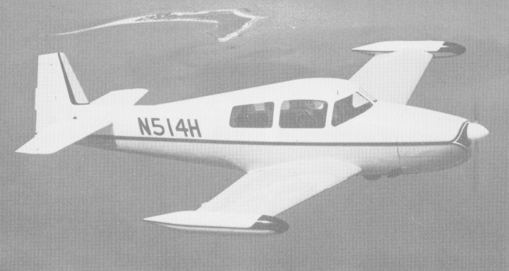
The 1960 Rangemaster G-1 was a five-seat version of North American/Ryan Navion (N514H) first flying on 10 June 1960.
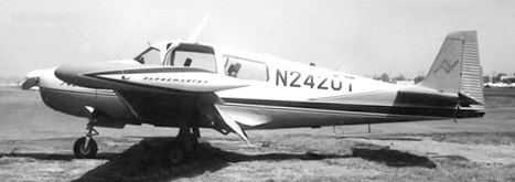
Navion Rangemaster N2420T
One of the later manufacturers introduced the Rangemaster model which had conventional doors and was produced from 1962 to 1970.
Ryan L-17 Navion
Navion Aircraft Co was founded in 1965 by the American Navion Society to provide spares and support for owners of Ryan/North American Navion lightplanes. All rights to the aircraft were acquired and a developed version, the five-seat Navion Rangemaster H, was produced before the company was liquidated and taken over by the Navion Rangemaster Aircraft Company.
In 1972 Navion Rangemaster Aircraft Co purchased the assets of the bankrupt Navion Aircraft Company, including jigs, machine tools, and spare parts to support Ryan/North American Navion lightplanes. In 1973 production of the Navion Rangemaster restarted, the first aircraft flying late the following year. Consolidated Holding Incorporated acquired control of the company in 1975 and announced plans to manufacture the Rangemaster H at the rate of one per week.
Navion Rangemaster
The Navion Rangemaster has been in and out of production in the past, and its 1977 revival has at times seemed surrounded more by promises than production. Where the factory formerly sold Rangemasters direct, all selling will now be done by Two Jacks, of Olive Branch, Mississippi. Two Jacks has, in fact, obligated itself to accept 100 Navion Rangernasters, to be built during 1976-78.