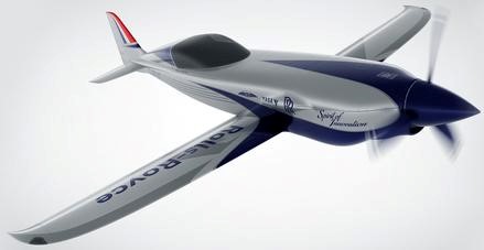
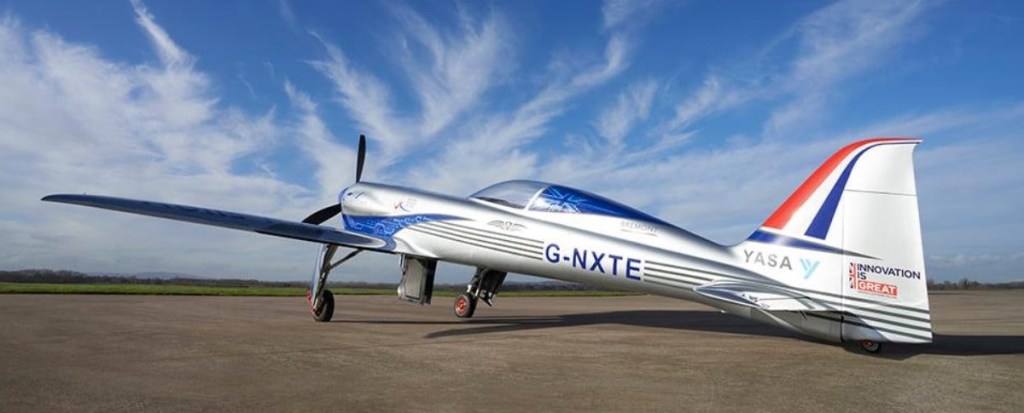
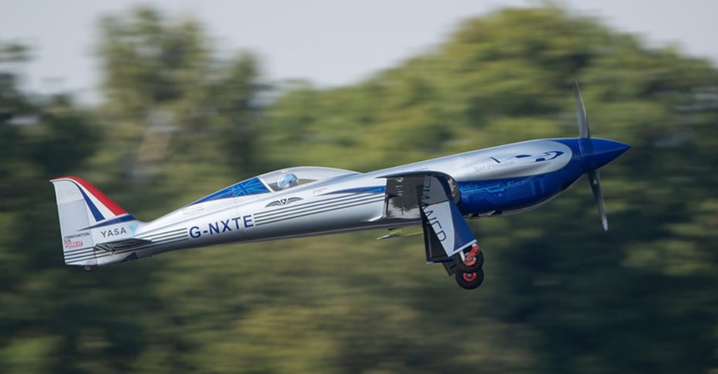
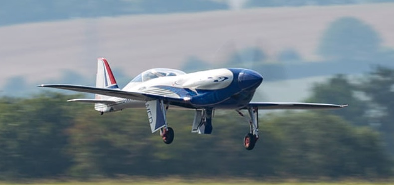
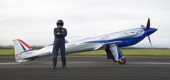
Rolls-Royce developed the ACCEL (Accelerating the Electrification of Flight) as an electric aircraft demonstrator racing aircraft to gain the all-electric air speed record, targeting over 480 km/h (260 kn). The existing electric aircraft record at that time was 182 kn (337 km/h), set in 2017 by a Siemens powered Extra 330.
Designed at Gloucestershire Airport, the project is partly funded by the UK government and involves partners such as electric motor and controller manufacturer YASA Limited and aviation start-up Electroflight.
The team aimed to reach the 1931 Schneider Trophy speed, which was won by a R-R-powered Supermarine S.6B, reaching 298 kn (552 km/h).
On 15 September 2021, Rolls-Royce announced the aircraft, named “Spirit of Innovation”, had successfully completed its first flight, flying from MoD Boscombe Down for fifteen minutes.
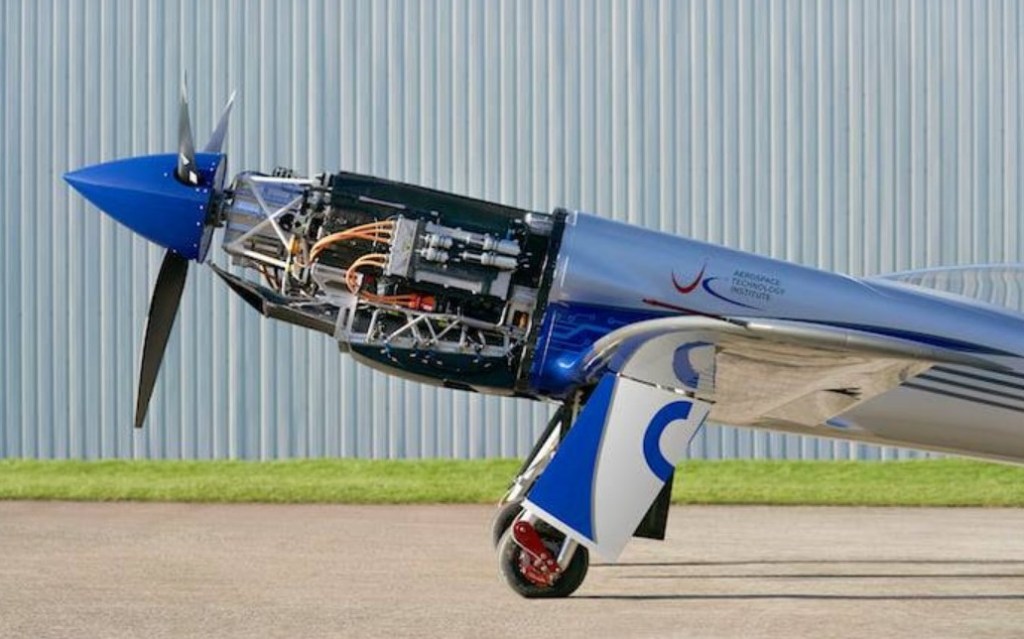
The 24 ft (7.3 m) span aircraft is powered by three high power density electric motors driving a single three-blade propeller spinning at 2,400 RPM, designed and manufactured by YASA, running at 750 volts and delivering over 400 kW (536 hp) combined from its 6,480-cell battery pack with cork insulation. Its cooled battery pack should have the highest energy density for an aircraft and should allow a 320 km; 170 nmi range.
It is derived from the carbonfibre Sharp Nemesis NXT racer, cruising at 282 kn (522 km/h) with a 350hp (260kW) piston engine, but reaching 355 kn (657 km/h) with a highly tuned engine. Battery power output will be 500 hp (373 kW) continuous, reaching 750kW (1,006hp) at maximum power. The battery, motors and control equipment weigh the same as the regular engine and fuel tank while the NXT has a maximum take-off weight of 1,200kg (2,645lb). Its 216 KWh battery pack weighs 1350 kg.
Rolls-Royce said that its all-electric Spirit of Innovation aircraft has set three new world speed records, making it the world’s fastest all-electric aircraft. The company has submitted data to the Fédération Aéronautique Internationale (FAI)— the World Air Sports Federation which controls and certifies world aeronautical and astronautical records—that at 15:45 (GMT) on 16 November 2021, the aircraft reached a top speed of 555.9 km/h (345.4 mph) over 3 kilometers, smashing the existing record by 213.04 km/h (132mph). In further runs at the UK Ministry of Defense’s Boscombe Down experimental aircraft testing site, the aircraft achieved 532.1km/h (330 mph) over 15 kilometers—292.8km/h (182mph) faster than the previous record—and broke the fastest time to climb to 3000 meters by 60 seconds with a time of 202 seconds. It subsequently reached a top speed of 623 km/h (336 kn), 555 km/h (300 kn) over 3 km (1.6 nmi), 532 km/h (287 kn) over 15 km (8.1 nmi), and was able to climb to 3,000 m (9,840 ft) in 3min 22s. The speeds achieved were accepted as world records for electric aircraft by the Fédération Aéronautique Internationale in January 2022.
During its record-breaking runs, the aircraft clocked up a maximum speed of 623 km/h (387.4 mph)—making the Spirit of Innovation the world’s fastest all-electric vehicle.
The D-12 was one of the most powerful engines of its era, and continued to swap records with other contemporary high-power engines. No British company could offer anything like it, and when Fairey imported 50 of the type (renaming them as the Fairey Felix) the Air Ministry had enough and ordered Napier & Son and Rolls-Royce to start work on cast-block engines of their own.
Arthur Rowledge, one of Napier’s chief engineers and the designer of the Napier Lion engine, became fed up with management and left for Rolls. In this one move any Napier design effort ended while Rolls’ got a boost. Applying every known advance since the D-12 was introduced, Rowledge designed the new engine to use supercharging at all altitudes, allowing it to outperform naturally aspirated engines by as much as they were willing to increase the boost pressure.
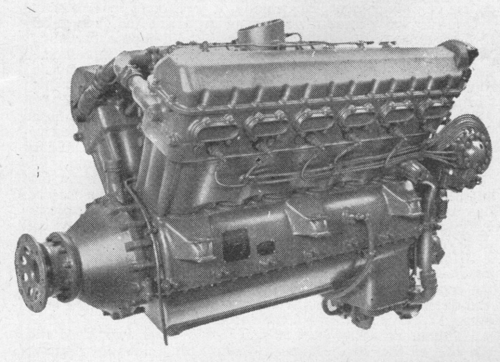
The year 1925 saw the beginnings of a new engine which differed radically from its forebears in having each of the two banks of six cylinders formed from a single aluminium-alloy block. Of 21.24 litres capacity, it was of compact design and first appeared, under the designation F.10, as a direct drive unit. During June 1927 Flight was able to announce that the F.10 had completed its official 100 hr type test at the first attempt, and had been granted a Certificate of Airworthiness. The maximum b.h.p. was 490 at 2,350 r.p.m. and the fuel consumption, at normal power and speed, 30 gal/hr. Dry weight was 760 lb.
The blocks were set at an angle of 60 deg, the cylinder heads, with the necessary inlet and exhaust passages, being cast integrally with the walls forming the water-jackets. Renewable valve-seating rings were screwed into the heads and the valve-guide bushes were of cast iron. The flanged joint between the upper end of the carbon steel cylinder liner and the head was made gas-tight by a soft aluminium ring, and near the lower end of the liner a sliding watertight joint was formed by means of a rubber ring fitted into a groove in the liner. Just below this joint a flange formed on the liner abutted on the crankcase and the whole assembly was held in position by long bolts. Where these bolts passed through the water space between the liners they were enclosed in aluminium tubes, swaged at the ends to make a watertight joint with the jacket casting. The two inlet and two exhaust valves per cylinder were operated by an overhead camshaft, through a separate rocker for each valve.
The three oil pumps were of the gear type and were driven by spur gearing from the vertical shaft which drove the water pump. Lubrication was on the dry-sump principle.
The engine was fitted with hand-starting gear, comprising a worm wheel incorporating a multi-plate clutch mounted on the sleeve carrying the main bevel wheel for the auxiliary drive; the clutch was set to slip when a predetermined torque was exceeded. In the event of backfire also the clutch would slip, thus saving the gears from damage.
In Kestrel engines of the types A and B, two Rolls-Royce Duplex carburettors were mounted between the cylinder blocks. The two throttles of each carburettor were connected by a pair of toothed quadrants, and one quadrant of each pair was mounted on the end of a longitudinal shaft so that all four throttles were opened and closed simultaneously and to the same extent. The carburettors were fitted with a device by which the flow of petrol from the float chamber to the jet was automatically regulated in accordance with altitude.
The supercharger consisted of a high-speed centrifugal fan mounted co-axially with the crankshaft at the rear of the engine and drawing air through the carburettors. The aluminium-alloy impeller, with radial blades, was driven through a speed-multiplying gear comprising a system of three planets. These were frictibnally driven from a pinion on the crankshaft by means of slippers, held in engagement with the insides of the gear rims by light springs. As the speed of rotation of the crankshaft-and therefore of the slippers-increased, the radial pressure of these springs was augmented by centrifugal force, and consequently the torque which the planets could transmit increased as the square of the speed. As the torque required to drive the impeller increased at a like rate, the gear was capable of driving the impeller with a predetermined margin of torque above that causing slip, which was constant throughout the working range of speed.
The object of this special friction drive was to protect the gearing against damage on sudden acceleration or deceleration of the crankshaft due to the inertia of the impeller. The impeller inertia, however, in combination with the friction drive, served to damp out torsional oscillations of the shaft which drove the camshaft and auxiliaries, including the supercharger itself.
For all the varieties of Kestrel so far mentioned the normal crankshaft speed was 2,250 r.p.m. and at this speed the unsupercharged low-compression engine developed 490 h.p. at sea level. The unblown high-compression types gave 480 h.p. up to 3,000 ft, the medium-supercharged models 525 h.p. at sea level and 500 h.p. at 3,000 ft, and the fully supercharged versions 480 h.p. at 11,400 ft.
The next series of Kestrels bore the series numbers IV, V, VI, VII, VIII, IX, X, XI and XII. Of these the IV, V and VI were fully supercharged, with 0.632, 0.5S3 or 0.477 reduction gear; the VII, VIII and IX were medium supercharged, with the same sequence of gear ratios; and the X, XI and XII were unsupercharged, with a compression ratio of 7A. The fully supercharged engines were rated at 600 h.p. at 11,000ft, and the medium supercharged and unsupercharged versions at 630 h.p. at 3,000ft and 575 h.p. at sea level respectively.
The ultimate in Kestrel development were the Series XIV, XV and XVI, fully supercharged, but more highly rated than the IV, V and VI. The supercharger ran at 9.4 times the crankshaft speed, whereas on the IV, V and VI it ran at 8.8 times that speed. The rating was 690 h.p. at 2,600 r.p.m. (an increase of 100 r.p.m. over the earlier engines) at 11,000 ft, and at 3,000 r.p.m. the output was 745 h.p. at 14,500 Oft. The weight was 975 lb.
Kestrel XVI
The Kestrel XXX was a later development for training aircraft, and had a rated power of 535 h.p. at 12,500 ft.
One key advance in the Kestrel was the use of a pressurised cooling system. Water boils at 100 °C at standard atmospheric pressure, but this temperature decreases with altitude. Since the amount of heat carried out of the engine is a function of coolant temperature and volume, if the coolant has to be kept below boiling point an increasing amount of fluid has to be used, along with an increasingly large radiator to cool it. The solution was to pressurise the entire cooling system, thereby not only preventing the decrease in cooling performance with altitude, but in fact increasing the boiling point even on the ground. The Kestrel was built to maintain enough pressure to maintain the boiling point at about 150 °C.
In May of the following year Flight again reported on the development of the “F” series, introducing the F.12, and desscribing it as “in a general way the geared version of the F.1W’ Later, fuller designations and characteristics of the “F” series were made known; thus the FXIA, FXIB, FXIIA and RXIM differed with regard to gear ratio and compression ratio; the FXI engines had a gear ratio of 0.632:1, and the FXII a ratio of 0.552:1. The letters A and B indicated compression ratios of 6:1 and 7:1 respectively. SubsequentIv, the FXIVA and FXIVB were added to the series; the FXIV had a gear ratio of 0.475:1.
During 1930 the “F” type engine was named the Kestrel, and yet another system of designation was introduced. The name was followed by the series number I, II or III, indicating 0.632, 0.552 and 0.475 reduction gear ratios respectively; then followed the letters A, B, MS, or S, indicating 6:1 compression, 7:1 compression, medium supercharger, or full supercharger.
The Kestrel was first produced in 1927 at 450 hp (340 kW), which soon improved in the IB version to 525 hp (390 kW). This variant saw widespread use in the Hawker Hart family that was the mainstay of British air power during the early 1930s. However it was not long before line improvements increased power dramatically; the V model provided 695 hp (520 kW) at 3,000 rpm with no basic change to the design, while the XVI used in the Miles Master delivered 670 hp (500 kW). Messerschmitt also tested its first Messerschmitt Bf 109 V1 prototype, bearing German civilian registration D-IABI, with a Kestrel engine in 1935 as the German designed intended engines were not yet ready. Junkers also used a Kestrel for the first prototype of the Ju 87 “Stuka” dive bomber. The Reich Air Ministry (RLM) acquired four Kestrel VI engines by trading Rolls-Royce a Heinkel He 70 Blitz as an engine test-bed.
Increased availability of higher octane aviation fuels in the late 1930s allowed the engine to be boosted to higher power levels without suffering from detonation, and the Kestrel eventually attained a power output of 720 hp (537 kW) in the XXX variant of 1940.
The Kestrel was produced in 40 distinct variants which can be divided into three main groups, normally aspirated, medium supercharged and fully supercharged. One variant, the Kestrel VIII was configured as a ‘pusher engine’ for the Short Singapore flying boat. Apart from supercharging, the variant differences centred around varying compression ratios and propeller reduction gearing.
The total production of Kestrel engines was 4,750. Unit cost in 1934 was £2,051. Further developments of the Kestrel were the Goshawk and the Peregrine (and therefore the Vulture).
Aircraft applications: Airco DH.9 Avro Antelope Blackburn Nautilus Blackburn Sydney Fairey Fleetwing Fairey Hendon Fairey S.9/30 Fairey Fox I, II, III and IV, IIIF Fairey Firefly II and III Fokker C.V Fokker C.X Fokker D.XVII Gloster Gnatsnapper Gloster TC.33 Gloster TSR.38 Gloster C.16/28 Handley Page Hamilton Handley Page Heyford Handley Page H.P.30 Hawker Audax Hawker Demon Hawker Fury Hawker Hardy Hawker Hart Hawker Hind Hawker Hornet Hawker Nimrod Hawker Osprey Hawker High-Speed Fury Hawker Hartebeeste Heinkel He 70 G-1 Heinkel He 112 Henschel Hs 122 Junkers Ju 86 Junkers Ju 87 Messerschmitt Bf 109 Miles Master Miles Kestrel Parnall Pipit Praga E-45 Renard R.31 Saro A.10 Short Gurnard Short Singapore Supermarine Scapa Supermarine Southampton Vickers 141 Vickers B.19/27 Vickers F.21/26 Vickers Type 150 Vickers Type 163 Westland Wizard
Other applications Speed of the Wind
Specifications: Kestrel V Type: Supercharged liquid-cooled 60-degree V12 engine Bore: 5 in (127 mm) Stroke: 5.5 in (140 mm) Displacement: 1,295.88 in³ (21.24 L) Length: 74.61 in (1,895 mm) Width: 24.41 in (620 mm) Height: 35.63 in (905 mm) Dry weight: 957 lb (434 kg) Valvetrain: Two inlet and two exhaust poppet valves per cylinder Supercharger: Gear-driven centrifugal type supercharger Fuel system: Rolls-Royce carburettor Fuel type: 87 octane petrol Cooling system: Liquid-cooled, pressurised to 300°F (150°C) Reduction gear: Spur, 0.553:1 Power output: 685 hp (511 kW) at 2,240 rpm for takeoff 631 hp (471 kW) at 2,900 rpm at 14,400 ft (4,400 m) Specific power: 0.53 hp/in³ (24.05 kW/L) Compression ratio: 6.0:1 Oil consumption: 0.18-0.35 oz/(hp/hr) (7-13 g/(kW/hr)) Power-to-weight ratio: 0.72 hp/lb (1.18 kW/kg)
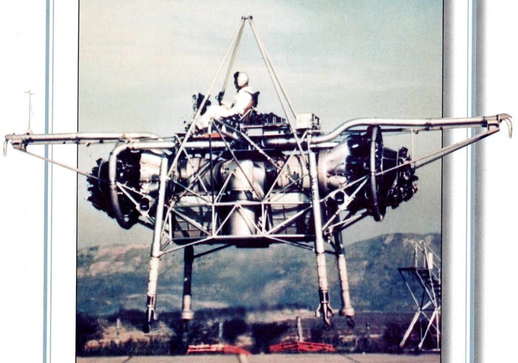
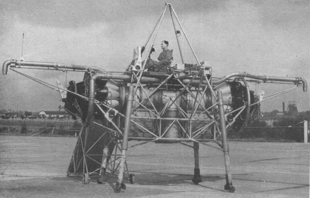
The Bedstead, officially called a Thrust Measuring Rig (TMR), was the brainchild of Doctor A.A.Griffith of Rolls Royce. It was a flat riser which hovered on the deflected exhaust gases of two Rolls Royce Nene jet engines. Compressed air nozzles provided directional control. The data gathered during the Bedsteads’ test programme in the mid 1950s led to the development of a special turbojet engine for jet lift, the RB108.
This was a radically new approach towards the development of vertical take off aircraft. Basically it consists of a tubular frame, said to measure about 20 ft. across, on which are mounted two Nene engines having a common, downward facing tail pipe. Space is also provided for fuel tankage and the pilot is seated in the normal attitude on the top.
The weight amounts to some 3.5 tons, and is a little less than the total maximum thrust from the 5,000 lb. thrust Nenes. The two engines are mounted horizontally, facing away from each other, the exhaust gases being turned through 90 degrees to enter a common downward directed tail pipe. The thrust so obtained provides for direct vertical jet lift of the rig.
Control in the pitch, roll and yaw planes is obtained by means of air jets bled from the Nene compressors. No aerodynamic control surfaces are used.
Capt. R.T. Shepherd, who was Rolls Royce’s chief test pilot until 1951, made the first fully free flight trials on August 3, 1954. During the previous 12 months or so, the ” jet lifter ” had undergone tethered flights, the amount of tethering being progressively relaxed as more experience was gained. The rig has since also been flown by Mr. H. Bailey, the company’s chief test pilot, and Sqn. Ldr. Harvey, of the R.A.E.
Flights have been made involving hovering and sideways and vertical movement. Landing is said to be very light and incurs no sudden drop. As with a helicopter, horizontal motion is produced by tilting the lift component, in this case from the propulsive jet, and a horizontal as well as a vertical thrust is obtained in this way.
Its pilot sat on a control station atop an entirely open-air framework of tubing, a calliope of ‘puff-pipes’ for attitude control arranged all around him. It was nicknamed the ‘Flying Bedstead’. NASA were interested in its reaction control system for their lunar lander simulator.
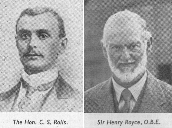
Rolls and Royce, met in Manchester in 1904. Rolls-the Hon. Charles Stewart Rolls-possessed wealth, an Eton-and-Cambridge education, a degree in mathematics and applied science, and a fine record as a motorist. He was a sportsman he had consistently displayed a daring at the wheel and a determined approach to the technical problems of motoring.
In the business of C. S. Rolls and Co., which he established with Claude Johnson in 1902. In 1903 he set a world speed record of 93 m.p.h.; but the car was a 70 h.p. Mors, and by the following year, when his books showed orders for a hundred Continental cars, he could still not find a British product which measured up to his standards.
At ten years of age Henry Royce started work as a telegraph boy, later attending a technical college, and serving a few years in the Great Northern locomotive shops at Peterborough. After a spell in an engineering works at Leeds, he set up a business in Manchester, making arc lamps and dynamos. The slump after the Boer War caused him to turn his ambition to cars. Disappointed with a foreign model which he acquired, he decided to put his own ideas into practice, and in 1903 he completed a two-cylinder car of 10 h.p., having handled much of the precision work himself.
One of his first three cars went to Henry Edmunds, who arranged the meeting in Manchester. The two men took to each other immediately, and having tried out Royce’s car, young Rolls undertook to sell its maker’s entire output. But he began to ply his partner with suggestions and demands.
The “two Rs” were first officially linked in business association at Christmas 1904, by a working agreement between the two firms; and thenceforth the Rolls-Royce car began.
By 1906 Royce’s production was large enough to allow Rolls to stop his sales of other makes of car, and Rolls-Royce, Ltd., was founded. Royce’s old partner, A. E. Claremont, became chairman; Rolls was technical managing director; and Royce was nominated chief engineer and works director.
Charles Stewart Rolls
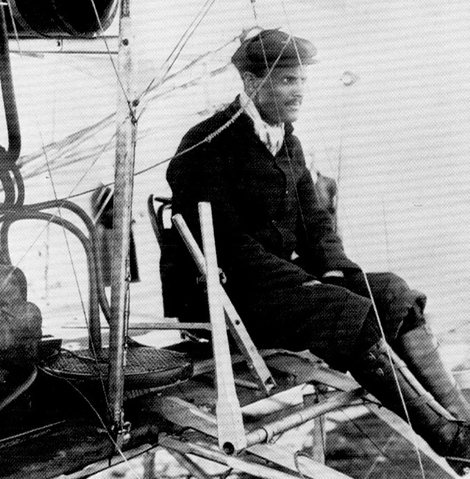
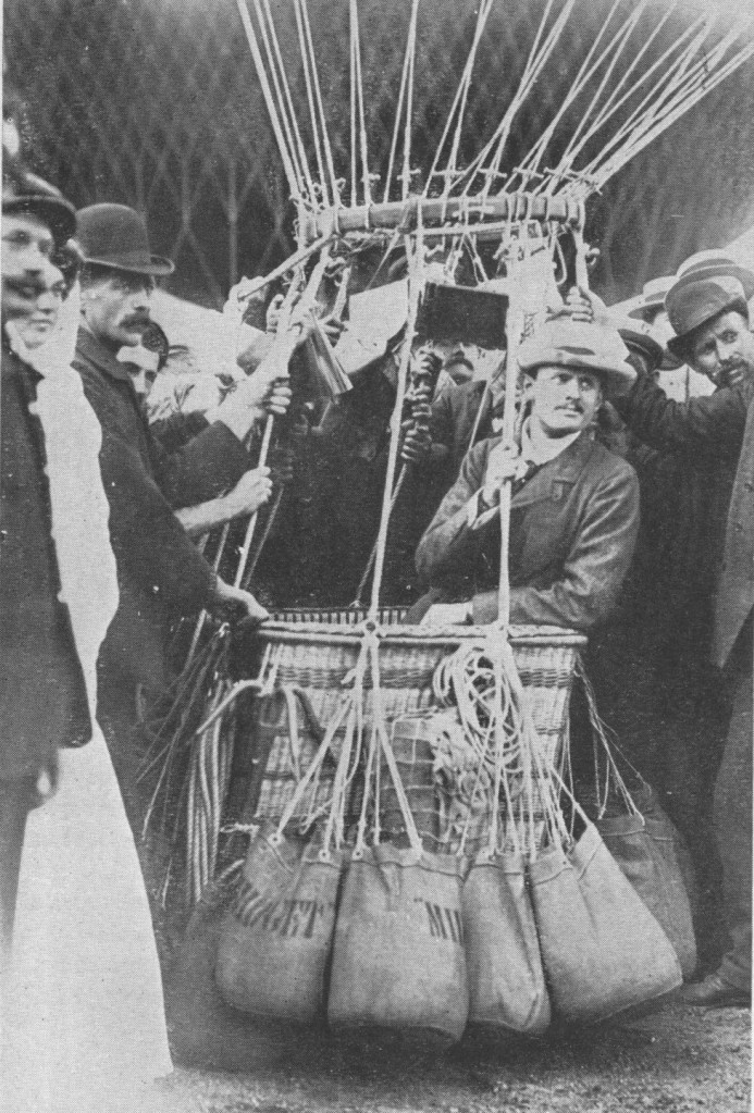
Rolls, who had become a member of the Aeronautical Society in 1901, was already a keen balloonist; then, having met the Wright brothers, he turned to heavier-than–aircraft. He was awarded his pilot’s certificate (No. 2) on March 8th, 1910-the very same day that Lord Brabazon received his No. 1. On the Wright biplane he made the first heavier-than-air crossing of the Channel by an Englishman, and the first double crossing by any aeroplane in history; but soon afterwards-on July 12th, 1910, he crashed to his death at the Bournemouth flying meeting, only 33 years of age. He was the first Englishman to die in an accident to a powered, heavier-than-air machine. His Wright Flyer broke up at 20 ft agl and he cracked his skull.
C.S. Rolls
In 1910 Royce became seriously ill and thereafter was absent for long periods from his new factory at Derby. He worked on in the south of France and on the south coast of England.
Following the British Schneider victory of 1929-made possible by the “R” engine-a baronetcy was conferred upon him, and he heard from his bed how an improved engine of this type sent a Supermarine S.6B to final victory in the Schneider Race of 1931. He died on April 22nd, 1933.
1914 Design of first Rolls-Royce aero engine-later named Eagle started. Company making engines of official pattern at Derby.
1915 Eagle on test six months after design initiated. Hawk designed and developed. Falcon designed
1918 Condor on test at 525 h.p.
1919 Alcock and Brown, in a Vickers Vimy (two Rolls-Royce Eagle Vills), mode first direct crossing of North Atlantic; flying time, 16 hir 12 min. Ross Smith and Keith Smith, in an Eagle-Vimy, made first flight from England to Australia11,130 miles in 124 hr flying time.
1920 Van Ryneveld and Quintin Brand, also in an Eagle-Vimy, made first flight from England to South Africa-6,281 miles in 92 hr 58 min flying time.
Between 1915 and 1924 Rolls-Royce Aero-engine production was: Eagle, 4,674; Hawk, 200; Falcon, 2,185; Condor, 327.
1925 Design of Rolls-Royce “F” series of engines (later called Kestrel) started.
1926 First “F” engine tested and delivered.
1927 The ” H ” engine-later the Buzzard-under development.
1929 Air Ministry decided in February to compete in Schneider Trophy Contest; Rolls-Royce asked to develop a racing engine. Within six months “R” engine was delivering 1,900 h.p. for a weight of 1,350 ]b. Installed in Supermarine S.6, which won Schneider Contest at 328.63 m.p.h.
1931 Rolls-Royce again asked to develop a Schneider Trophy engine to help secure a third victory, which would gain Trophy outright for Gt. Britain. Outcome was improved “R” engine of 2,360 h.p., weighing 1,630 lb. Schneider Trophy won outright. Later “R” engine gave 2,530 h.p. and enabled world speed record to be raised to 407.5 m.p.h.
By 1931, during the Great Depression, Bentley was having financial difficulties. When funds ran out in 1931, the receivers were negotiating with D.Napier & Sons Ltd for the sale of the remains of Bentley. However, Rolls-Royce put in a secret bid through a Liechtenstein company, and secured Bentley Motors for £125,256. For this, Rolls-Royce got the factory equipment, a number of incomplete car chassis, and the services of Walter Bentley for three years.
1932 Design of the P.V.12 engine (later called Merlin) started. (P.V. denoted private venture.)
1934 Merlin completed its first 100 hr run at 790 h.p.
1936 Merlin completed Service Type Test at 975 h.p.
1938 Building of Crewe factory started.
1939 First Merlin built at Crewe. Design and development work started on 37.V.12 engine, later named Griffon. Building of Glasgow factory begun in August. 1
1940 First Merlin built at Glasgow. First test run of Griffon.
1942 Quantity production of Griffon started.
1943 First Rolls-Royce turbojet-the Welland-passed its 100 hr type test; thrust, 1,700 lb, weight, 850 lb. Design of Derwent 1 started.
1944 Deliveries of Welland begun, for installation in Gloster Meteor. Design and development of Nene started.
1945 Meteor powered with Derwent Vs broke world air speed record at 606 m.p.h. In September a Meteor was flown with two Rolls-Royce Trent turboprops, being the first turboprop aircraft to fly. By this year power of Merlin had increased to over 2,000 h.p.
1946 World airspeed record again broken by a Derwent-Meteor; speed 616 m.p.h.
1947 Pratt and Whitney signed licence agreement for manufacture of Rolls-Royce Nene and Toy. Nenes in production at Derby. Trans-Canada Airlines started operations with Merlin powered Canadair North Stars.
1948 First public appearance ofAvon turbojet at S.B.A.C. Display. Belgium signed licence agreement for manufacture of Derwents.
1949 Dart turboprop type-tested at 1,000 h.p. B.O.A.C. intro- duced Merlin-powered Argonauts (similar to North Stars).
1950 Australia signed licence agreement to build Nene and Avon. Hispano signed agreement to make Nene and Toy.
1951 English Electric Canberra, with two Rolls-Royce Avons, made first non-stop transatlantic crossing by a jet aircraft the first of numerous record flights by Avon-Canberras.
1952 Sweden signed licence agreement to build Avon.
1953 Avon-Canberra flew from London Airport to Darwin, Northern Australia, in 22 hr 21 sec. Avon-powered Hawker Hunter established world air speed record of 726.6 m.p.h.; Avon-powered Supermarine Swift later raised record to 735.7 m.p.h. Ministry of Supply opened new factory at East Kilbride, Lanarkshire, to augment production of Avons for the R.A.F. (in addition, Avons were being made by the Bristol Aeroplane Co., Ltd., D. Napier and Son, Ltd., and the Standard Motor Company.)
1954 By May 1954 British-built Rolls-Royce gas turbines had completed 23 million flying hours; Merlins had cornpleted over 5.1 million flying hours in commercial service. By the end of the year over 185,000 Rolls-Royce piston and gas-turbine engines will have been built.
LHTEC (Light Helicopter Turbine Engine Company) is a joint venture between Rolls-Royce and Honeywell founded in 1985. The company was originally a partnership between the Allison Engine Company and AlliedSignal Aerospace . In 1995 Rolls-Royce acquired Allison, and AlliedSignal merged with Honeywell in 1999, and adopted its name.
In 1964 Rollasons and the Tiger Club sponsored a competition for a midget racing aircraft which could be used for Formula One air racing. The winner was the Luton Group’s Beta, and after the prototype was attempted by that group, the design was taken over by Rollasons.
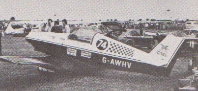
Beta B2A G-AWHV Continental C90
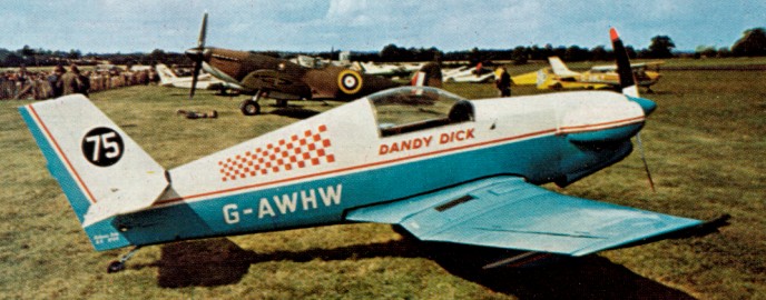
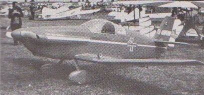
The Beta is a single seat sporting monoplane of all wood construction. The wing employs an NACA23012 aerofoil section and consists of a rectangular centre section and tapered outer panels. The wing is made up of a single main spar and auxiliary rear spar, wood ribs and plywood covering. The mass balanced wooden ailerons are fabric covered. Flaps are optional. The fuselage is a semi-monocoque structure consisting of elliptical wooden frames and plywood covered. The cantilever tail unit has a ply-covered fin and tail plane and fabric covered control surfaces. The fixed undercarriage has rubber in compression shock absorbers on early models, but spring steel legs on later models. Fuel capacity is 10.5 Imperial gallons. Four versions of the Beta are available, the basic difference being the engine fitted.
Beta B4 G-AWHW at Sywell 1975. Continental O-200-A
Beta B1 Engine: Continental A65, 65 hp Wing span: 20.05 ft Length: 16.08 ft
Beta B2 Engine: Continental C-90, 90 hp
Beta B2A Engine: Continental C-90, 90 hp Undercarriage: spring steel
Rollason Aircraft and Engines Ltd. Initially an aircraft sales and service organization. Began aircraft construction in 1957 with Druine Turbulent single-seat light monoplane powered by a Rollason-converted Ardem motor car engine. Production was carried out at their works on the old Croydon Aerodrome with first flights generally taking place at Redhill.
In 1961 built two-seat Druine Condor with 75 hp Continental engine. Later versions used more powerful Continental engines. Rollason also rebuilt a number of Tiger Moths and other aircraft, and carried out seaplane conversions of the Tiger Moth and Turbulent.
In 1973 the company moved from Croydon to premises at Shoreham. Tiger Moth work was concentrated at Rochester, with Redhill providing back-up to both bases and the hub of the sales part of Rollasons.
The end of 2005 concluded a series of workshops around key ideas for the new LS10. One key principle was not to “DG-ize” the LS10 but rather maintain the typical LS characteristics. The LS 10 will differ from the existing model by all LS10 gliders being engine-ready. To simplify production all LS10 gliders will have the engine box built into the fuselage. All LS10 ordered in the glider-only version will offer the option of retrofitting a sustainer engine later. The typical LS toe brake actuation will be replaced by a drum break actuated by the dive brake lever (in its fully deployed position). The “Haenle” guides for the ailerons remain.
There are no changes to the LS-type elevator assembly, but the outer wing panels trade-in the old threaded bolt for a spring loaded locking pin for easier assembly.
The skids on the wingtips remain (no wheels) as there will be no self-launching version.
All versions of the LS10 feature 4 wing panels, i.e. each wing will be partitioned into two panels for all versions and configurations of the LS10. This design ensures easier assembly and allows for the use of a shorter trailer. As for the location of the paring between inner and outer panels, the further out toward the wing tip the designer places the divide, the easier the assembly and the cheaper and lighter the required connection for the wing spar. In the limit of parting at y=7.25m however, the resulting wing tips of 0.25m for the 15m wing plan form lead to sub-optimal performance characteristics. If the divide is moved too far toward the wing root, the outer panels become so heavy that they cannot be handled by one person. In addition, this also raises the total weight of the wing substantially, which in turn leads to a more expensive overall wing design. The best compromise is for the parting to be at y=7m. This results in 2m outer panels for the 18m version, a size that can still be handled effectively by one person. Combing the resulting 0.5m wingtips for the 15m version with “high” winglets leads to an aerodynamically optimal plan form for this version as well.
The 18m wing plan form will feature the well-known LS curved winglets.
All LS10 gliders are designed to accommodate a bug wiper system. Integrating this option into the design of the LS10 allows for the installation of a lower drag bug wiper system.
Meanwhile the second LS10 was construction at the Bruchsal facility according to the original Rolladen-Schleicher design. This aircrafts construction was begun by Rolladen-Schneider and was suffering from delays due to the well-known legal problems. The test pilot was Micro Scholz.
Its design is still identical to the “original”, as is production no. 1. The design of number 3 is currently being completed. It will include a number of improvements and will serve as the basis for serial production.
In parallel with the flight tests staff worked on detailed solutions and modifications. The extensive testing of the two prototypes resulted in new fairings at the lower part of the vertical fin, but the biggest changes took place in the cockpit e.g. the position of the rudder pedal cavity foot tub was changed. Now there will be room for big feet. To further improve the view out of the cockpit the instrument panel could be further lowered – without loosing space for the instrumentation, and a Piggott-Hook was installed.
The operating forces of the water ballast system were reduced. The shape of the opening levers was optimised. The flap lever the changes in flap setting works more precisely and pilot-friendly – the handle is coated with fine leather. The decompression lever for starting the engine was moved and now is very well accessible. The position of the trim knob was optimized ergonomically and functions much better. The rudder pedal handle now retracts in the seat pan after use in the LS10.
A very tall pilots will fit in the LS10 by using an optional separate headrest which can be installed instead of the back support. The change can be done in a minute.
Span: 15 m Area: 10.4 sq.m Aspect ratio: 21.7 Airfoil: Lemke Empty Weight: 250 kg Gross Weight: 525 kg Wing Load: 50.5 kg/sq.m Seats: 1
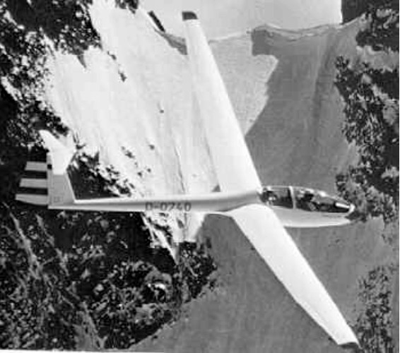
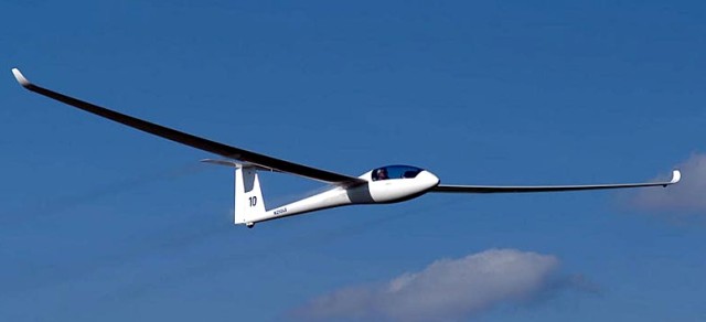
Designed by Wolf Lemske to Standard Class specifications, and built by Walter Schneider, the prototype was completed in March 1994, although the fuselage was first flown with LS6 wings in 1993.
Wolf Lemke had recommended further comparison flights with the LS6 and LS7 models, but under different conditions. He increased the angle of incidence between wing and fuselage for improved thermalling and good take-off handling. He used the unmodified LS6-c flapped wing and added winglets.
Winglets come as standard and a fin ballast tank is an option. Approach control is by top surface Schempp-Hirth airbrakes. Wingtip extensions bringing the span to 18 m are also an option.
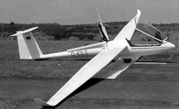
From the beginning the fuselage was designed for the installation of an engine and even the installation of a total rescue system was initially considered. As LS8-b the airplane can be ordered also with engine preparation only, this facilitates retro-fitting of a sustainer engine considerably.
Typical for LS the wheel brake is heel operated via the rudder pedals; the manual however terms it emergency brake only due to rapid brake pad wear. The beefed up 575 kg version has a 5 in wheel replacing the 4 in one, thus improving ground handling on grass runways substantially. Retracting the undercarriage also brings the belly release up into the fuselage.
The instrument panel tilts up with the canopy and an emergency exit assistance is optionally available.
The design of the LS8-s with variable wing span caters for pilots, who prefer to fly standard class competitions and, in addition want the performance of 18 meters. It’s also easier to accommodate the glider in a tight hangar having only 14.20 meters span without Winglet. The LS8-a is also available as a ‘skinned down’ version with 15 m only.
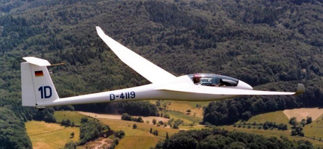
The glider has the characteristically double tapered wing with Wortmann profile and kink in leading and trailing edge. Adding the 18-Meter-tips with the noticeably smaller winglets the pilot experiences yet another substantial improvement of flight performances. Thus the lift/drag ratio rises to 48 and minimum sink improves to 0,51 m/s. in addition, 190 liters of water can maximally be carried in the 4 wing tanks, such requires center of gravity correction with water in the fin tank. All control connections are made automatically; double flange airbrakes are installed in the upper carbon fiber sandwich surfaceThe engine installation of the LS8-st with a Solo 2350 weighs complete with Fuel approx. 50 kg, made up for by the all up weight increase to 575 kg.
The original pneumatic retraction mechanism proved expensive and unreliable; DG replaced it with the proven linear bearing actuator for their production version. Operation of the 15 KW engine kept deliberately simple with the DG proprietary control unit. Travel distance with sustainer is approx. 300 km.
After the acquisition of Rolladen Schneider by DG-Flugzeugbau in July 2003 production of the LS8 continued very successfully despite initial legal problems. The finish of the airplanes manufactured at DG is reportedly noticeably better. The LS8 will be available again as an “LS8-s” (and not as “DG-700” or similar). We will continue the 15m version as well as the 15/18m version and the Turbo with the newly developed engine actuation. Delivery is possible from summer 2004.
Variants:
LS8-a Top performance with 15 m wing span
LS8-s High Performance Sailplane with 15 or 18 m of wing span By adding the 18 meter tips the Standard Class Glider LS8 becomes the LS8-s. Despite the bigger wing span the outstanding flying characteristics of the LS8-a stay the same but now with performance numbers which are comparable to the open class of the seventies. Although there are no wing flaps the LS8-s has reached best possible results in 18 meter class competitions under weak but also at best possible weather conditions. Obviously the wing section (a derivative of the LS6, as it is well known) is still a match to the most actual airfoil designs. The combination of very easy handling qualities, of having no problems when encountering turbulent conditions, minimum performance loss because of dirty or wet wings means a well proven competition glider which is also suitable for club operations or flying just for the joy of it. For the LS8-s an increase of the maximum take-off weight from 525 to 575 kg could be done for the 18m version in combination with the shock-absorbing retractable 5″main wheel.
LS8-t High Performance Sailplane with 15 or 18 meters of wing span and self-sustainer As the popularity of the LS8-s began to increase more and more the question about a self-sustainer version was heard. Being able to get home on a weak day and travel by glider beyond the weather borders becomes reality with a self-sustainer engine. Furthermore the LS8-s with the increased wing span carries the additional weight of the engine installation better than a pure 15m sailplane. So we made the LS8-st with a self-sustainer, the LS8-s “turbo”. The mold lines of the LS8-s were not changed – it was not even required to enlarge the fuselage. The engine is the Solo 2350 two stroke two cylinder motor which is already well proven as a propulsion for sailplanes. The rigid two blade propeller is produced by Technoflug. With an additional weight of about 40 kg for the engine installation plus 10 kg of fuel there results a climb performance of 1 to 1.5 m/s and a range of 300 km or an endurance of 1 hour The propulsion system was purposefully made as simple as possible. The engine plus propeller is very easy to install / uninstall. If a customer should like to install the engine later, he can purchase a only motor-prepared version, too.
At the 1995 World Championships at Omarama, New Zealand, LS-8’s scored 2nd, 4th and 5th in the Standard Class.
LS8 Standard Equipment – automatic control system connectors retractable and sprung undercarriage C.G. hook, retractable with landing gear Nose tow hook adjustable rudder pedals wheel brake Piggott-Hook canopy with instruments panel hinged up front infinitely adjustable trim system oxygen flask receptacle radio antenna in vertical tail fin standard instrument panel side pocket double tapered wing in Carbon-sandwich-construction 15m winglets in Carbon-construction ready to use water ballast system with funnel ailerons in Carbon-construction upper surface, double height air brakes horizontal tail plane in Carbon-sandwich-construction elevator in Carbon-Kevlar-construction all control surface gaps sealed backrest including headrest temporary hinge at canopy rear for clean separation during emergency jettison total energy connection in vertical fin safety harness (multiple point buckle type) registration signs Cotton canopy cover Optional Equipment Tail dolly, covers for wings, leather upholstery, every instrument system offered, tail wheel 210x65mm, contest numbers, etc.
LS8 15m / 18m Fuselage Length 6,72 m Fuselage Width 0,61 m Fuselage height 0,80 m Wing Span 15,0 m / 18,0 m Wing Area 10,5 m 11,4 m Aspect Ratio 21,4 / 28,4 Min. Wing Loading about 32 kg/sq.m / ca. 30 kg/sq.m Max. Wing Loading 50 kg/sq.m / 46 kg /sq.m LS8-s /st: 50 kg/sq.m Empty weight approx. 265 kg / 270 kg Max. Take-off Weight 525 kg LS8-s / st: 575 kg Max. Cockpit Load 110 kg Best Glide Ratio approx. 43 / 48 Minimum Sink Rate approx. 0,59 m/s / 0,51 m/s Seats 1
LS8-st Engine Solo 2350 ca. 18 hp Fuel capacity 13 l Climb rate in powered flight 1 -1,5 m/s