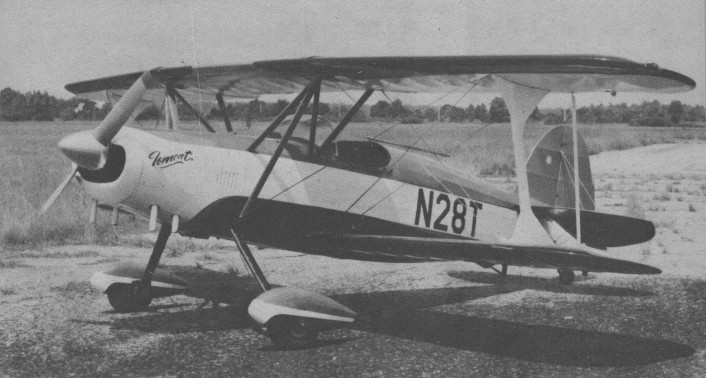
Tomalesky TF-1 Tomcat

Pete Tomalesky in early 1970 began the project to design and build a two-place, side-by-side biplane he called the Tomcat. He later removed the tubular spring gear and fitted a one-piece flat aluminum gear in its place. First flying in November 1973, he flew the Tomcat N28T in several I.A.C. amateur acrobatic contests.

“The Tomcat was intended to be an aerobatic/sport plane, and it uses a fuel-injected 160-hp Lycoming. The airframe will accept an engine with as much as 300 hp, and with a sliding canopy fitted, the Tomcat would be a highly competitive acrobatic machine

Mike Tomalesky describes the Tomcat’s construction as being of typical steel and wood, with a wingspan of 24 feet (top wing) and 181/2-foot length. All airfoils are fully symmetrical, and four interconnected ailerons are featured.
“I’ve dive-tested the Tomcat to 200 mph,” says Mike, and with the 160-hp engine it cruises at 110 mph and climbs at 1200 fpm. I’ve tried some 70 different aerobatic maneuvers and variations, including outside loops, point rolls and several inverted flat spins,”

The Tomcat was sold to the Suncoast Pilot’s Club at Clearwater Airport, and numerous pilots have since checked out in-it. Mike says he’s joining the club so he can put more time in on the Tomcat, which he hasn’t flown for some time. He describes the craft as highly responsive in pitch and roll, and says, “it does not get heavy prior to the stall, which is only brought on by a lot of work on the pilot’s part. Rudder control is excellent.

In aerobatic flying, entry speed of 140 mph IAS is used for loops, hammerhead turns, taiislides, point rolls and slow rolls. A 30-second slow roll has been recorded, with a minimum loss of altitude. “Four-and eight-point rolls are crisp, and 16-point rolls, at which 1 was very good, are possible,” mike enthuses. Square loops are entered at 160 mph, usually out of a hammerhead turn. Most rolls are done at cruise power, and Mike reports that snaps are fantastic. He says, “A real, fast snap can be done at 85 mph with ailerons and power added. Snaps out of knife edge are entered at from 110 to 120 mph.

Mike enters spins in the Tomcat at the usual stall speed, with no aileron required for a fast, tight spin, and recovery is virtually instantaneous, using conventional opposite rudder and forward stick. Spins do tighten up after six to eight turns, he says. Inverted spins are entered at stall speed and are simple to perform.

Outside loops from top around are entered at 80 mph, with speed at the bottom from 160 to 180 mph, depending on how many negative C’s are pushed. “At no time in the 100 hours of constant, rugged aerobatic flying I did,” says Mike, “was any part of the Tomcat damaged or deformed, and no abnormal flight characteristics were noted in any configuration.

Mike’s dad Pete began building the Tomcat in 1971 when he was operating a company called Tru-Flight near Clearwater Executive Airport, which was involved in building complete and partial aircraft. Construction time on the Tomcat ran to 14 months, or some 2000 hours, with the first flight taking place at Clearwater Airport in early September 1972. Virtually no modifications or adjustments were required, except to tighten the flying and landing wires and repair a cracked cowling.

TomcaCs fuselage is built up from 4130 steel tubing, gas welded, with spruce stringers attached to birch formers. The firewall is stainless steel; the nose bowl and wheel pants are f iberglass landing gear was an original steel rod design, later modified to one piece flat stock aluminum, with Cleveland brakes and 600 x 6 wheels and tires. A 36-USgallon aluminum fuel tank is mounted forward of the cockpit. The entire fuselage is fabric covered and doped.

Wing ribs are routed from five-ply birch plywood, and the spars are spruce, with laminated spruce wingtip, bows, leading and trailing edges are of aluminum, and the four identical ailerons are interconneded, actuated by push-puli tubes in the bottom wings.

The tail surfaces are outlined with 4130 steel tubing, ribs are bent sheet steel, the entire structure gas welded. An aluminum trim tab is on the left elevator only, operated, by a vernier control at the pilot’s left. Two sets of streamlined flying wires form the leading and trailing edges ‘of the stabilizer, with the entire structure fabric covered. The elevator is push pull tube operated, the rudder actuated by braided stainless steel cables.

Inside the cockpit, the pilot is provided, with a central control stick, interconnected with a shorter, removable stick for the passenger. Toe brakes are on the pilot’s side, with smaller, brakeless pedals on the passenger’s side.

The throttle and mixture control, originally at center, have been moved to the pilot’s left side, but a central throttle can be connected for student/passenger use. A radio navcom is located between and forward of the pilot’s legs in the center console, which also has a map storage area below the radio.

On the panel in front of the passenger’s seat are switches and circuit breakers, including master switch, turn and bank, electric fuel pump, nav lights and radio switch. Tomalesky placed the pilot seat six inches forward of the passenger’s seat to facilitate elbow clearance. Both seats are of fiberglass, bucket-type, with aerobatic seat belts and shoulder harnesses.

The baggage compartment is placed immediately behind the seats at shoulder height, with entry through a full-width aluminum door with a key lock. Baggage capacity is 50 pounds.

The 36-gallon fuel tank includes a 21 gallon header tank located at lower right ahead of the passenger’s rudder pedals, designed to house the flop-tube fuel pickup; it serves as the inverted fuel system. The fuel tank is double vented, on the bottom of the fuselage and on the top wing. Fueling is accomplished through a centrally located cap forward of the windshield.

A full oil inverted system with check valves and collecter tank are mounted on the firewall, and provisions have been made for mountings for tracks on the fuselge sides and atop the forward turtle deck to accommodate a full sliding canopy.

One of the few modifications made was a change from the original exhaust system, routed out through the bottom center or the engine cowl to four straight stacks protruding from the lower cowl. This change was made after one of the longer stacks fatigued and was lost in flight.

So far, says Mike Tomalesky, some 500 hours have been logged by a number of pilots flying the Tomcat, many carrying passengers in aerobatic demos.

Engine: Lycoming IO-320-B1A, 160 hp
Propeller: Fixed pitch
Wingspan Top: 24 ft 0 in
Wingspan Bottom: 22 ft0 in
Airfoil section Top: 63015
Airfoil section Bottom: 2300 Series-symmetrical
Length: 18 ft 6 in
Height: 7 ft 0 in
Wing area: 133 sq.ft
Gross weight: 1725 lb
Empty weight: 1154
Useful load: 571 lb
Baggage capacity: 50 (max)
Fuel capacity: 36 USgal
Seats: 2 side by side
Top speed normal: 160 mph
Cruise speed: 110 mph
Stall speed: 55 mph
Rate of climb: 1100 fpm
Tomalesky

Pete Tomalesky, Tomalesky Aviation, Urnatilla Municipal Airport, Umatilla, Florida 32684, USA.

At Urnatilla Municipal Airport, Pete Tomalesky has several other “Cats” in work – one project under construction is an enclosed cabin biplane, the Polecat, with tandem seating, and another is a strut braced mono designed for airshow flying.

The third, scheduled to fly first, is called the Topcat, a two-place, open cockpit bipe with tandem seating; it will carry a 200-hp IO-360 with a constant speed, or maybe a 260-hp Lycoming if Mike can find one at the right price. This particular project,” says Mike, “is being developed for amateur builders, and plans and possibly kits will be offered if public interest warrants it.”

Tokugawa Kaishiki No. 1

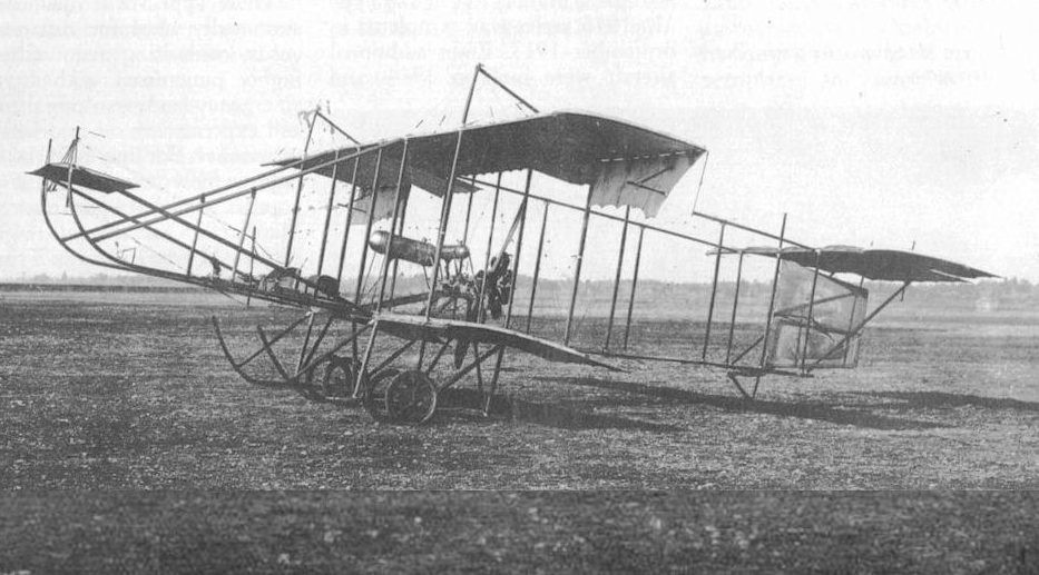
Japan’s very first Japanese-designed and manufactured aeroplane was the Kaishiki No. 1 (kaishiichigouki, 会式一号機), pusher aeroplane (propeller is behind the pilot, pushing the craft, as opposed to the puller type we commonly have nowadays that leads the aircraft) which was designed and flown by Captain Tokugawa Yoshitoshi (surname first), on October 13, 1911 at Tokorozawa in Saitama-ken (Saitama Prefecture).

The motor and propeller came from France, but everything else came from or was built in Japan. The aircraft’s frame was mostly made from hinoki (Japanese cypress), and was covered by two layers of silk glued together with sounds like liquid rubber.

All attachment fittings, bracing wires and turn buckles were purchased from iron works companies or bought from local hardware shops.

Differences from the Farman III design included a reduced wing area, which gave it more speed. The aerofoil had a larger front curve which was thought to provide better lift. Other differences between the Kaishiki No. 1 and the Farman III include the fact that ailerons were on the upper wing only, and the tail was simplified by having a single horizontal tail surface.

As well, the engine and propeller were mounted higher than in the original design, and therefore the undercarriage could be shortened. A windshield was added for the pilot.

When the aeroplane was constructed, it was called the Tokugawa Type, but was later officially identified as Kaishiki No.1 Aeroplane.

The aeroplane was moved to the Army facility and flying field at Tokorozawa where it made its first flight on October 13, 1911, piloted by Captain Tokugawa.

Captain Tokugawa Yoshitoshi

A later test flight on October 25, 1911 achieved an altitude of 50 meters (164 feet), reaching a top speed of 72 kilometers per hour (45 miles per hour).

Further testing had it reach 85 meters (278 feet) in altitude and flying a grand distance of 1,600 meters (1 mile).
Continued testing convinced the flight crew that the propeller ground clearance wasn’t high enough, as the blades would hit the grass below, slowing it down, causing the Kaishiki No. 1 to lose power.

Yamada dirigible and Kaishiki No.1

Actually, it was only after the providing greater clearance that the aircraft was given the Kaishiki No.1 moniker.
More changes ensued, including changeable landing skids in case one broke; twin rudders replaced by a single and larger rudder which was part of the advantage of the gained from the propeller slipstream meaning improved directional control.

Longer interplane struts on the aircraft were added to provide more spacing between the two wings.
One other alteration from the Kaishiki‘s original design was the removal of the pilot windshield, while it did provide protection from bug’s flying in the pilot’s mouth while screaming for joy as he flies through the air, the team felt that pilot needed to feel the air so as to get a better sense of the aeroplane’s speed.

Kaishiki No.1
Engine: 1 × Gnome Omega 7-cylinder, 50 horsepower
Propeller: 2-bladed wooden Chauvière
Length: 11.5 m (37 ft 9 in)
Upper wingspan: 10.5 m (34 ft 5 in)
Lower wingspan: 8.0 m (26 ft 3 in)
Height: 3.90 m (12 ft 10 in)
Wing area: 41.0 sq.m (441 sq.ft)
Empty weight: 450 kg (992 lb)
Gross weight: 550 kg (1,213 lb)
Maximum speed: 72 kph (45 mph)
Endurance: 3 hr
Crew: 2

Tokyo Imperial University Kokenki

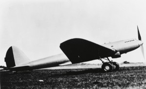
The aviation laboratory of the Tokyo Imperial University immediately became a mecca for Japanese students of aeronautics. Among its foremost achievements was the Kokenki, an experimental long-range monoplane that employed a domestically built airframe and a revamped version of a German engine. The plane flew over the Kanto Plain region, which includes Tokyo and its neighbouring prefectures, for 62 hours non-stop after taking off on May 13, 1938. The flight translated into a cruising distance of 10,651.01 km, a world record at the time and still Japan’s only aviation record certified by the International Aeronautical Federation.

Tokyo Imperial University Aeronautical Research Institute

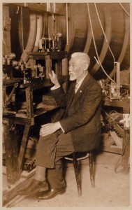
Professor Tanakadate, who started out as a researcher of geomagnetism and earthquakes, became interested in aviation after witnessing the flight of an airship in France in August 1907, while attending a Paris meeting of the General Conference on Weights and Measures. That experience, along with the findings he gleaned from an aerodynamics book he obtained from a British researcher, stimulated his interest in aviation science and set him on course to become one of Japan’s earliest and most important pioneers in the field.

Prof Tanakadate Aikitsu

On returning home, Tanakadate built a wind tunnel, the first such device in Japan. His apparatus, created from a nagamochi, a wooden drawer used for storing kimonos, was fed air from one side and had a small glass window in the side through which to observe how a scale-model airplane, hung from the ceiling inside the tunnel, would react to the air flow. He may have used the wind tunnel to test scale models of the first glider to fly in Japan.

Tanakadate frequently emphasized that it was vitally important to fully understand the basics of all related phenomena when it came to aeronautical research. His advocacy for comprehensive learning resulted in the opening in 1918 of Aeronautical Research Institute attached to the University and the commencement of an aeronautical course in the Department of Shipbuilding. This course expanded to become the Department of Aeronautics in 1920.

Tokyo Aiba-Tsubame 8 / Aiba-Tsubame 9

Aiba-Tsubame 8

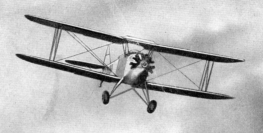
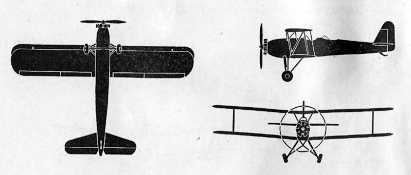
The Aiba-Tsubame 8 was an Advanced Trainer. Only the one was built.

The Tokyo Aviation Company modified the Aiba-Tsubame Model 8 trainer aircraft into Aiba-Tsubame Model 9.

Aiba-Tsubame 8
Engine: Tokyo Jimpu Radial, 150 hp or Gasuden Kamikaze 3-type, 160hp
Span: 29′ 6″ / 8.9m
Length: 22′ 10″ / 7m
Height: 6′ 6″ / 2.65m
Wing area: 22 sq.m
MTOW: 900kg
Max speed: 98 mph / 160km/h
Service ceiling: 4,400m
Range: 580km
Endurance: 4 hr

Aiba-Tsubame 8

Todhunter Blue Wren

Despite being registered as a microlight, it is really the prototype of what was hoped to become an amateur-built self-launching glider, built from a design that was originated by Reg Todhunter in Australia in the mid 1950s. Construction work begun in early 1980 and the aircraft first flew at Tocumwal, NSW, on 08-07-84 under a permit to fly issued by the Gliding Federation of Australia. It was then air freighted to California to take part in a homebuilt sailplane design competition instigated by the Soaring Society of America. The fly-off took place at Tehaehapi over 1-3 September 1984 and was won by the Rutan Solitaire. The aircraft was imported into New Zealand in 1996 by Neville Swan, following the death of the designer.

Although a glider, the aircraft was registered as a microlight in New Zealand (ZK-JGQ). The initial engine (a JPV PUL 425 horizontal twin 22 hp ) was replaced by a Koenig 3 cyl of 24 hp.

Todd 1909 Biplane

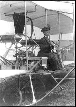
Miss [E.L.] Todd in her aeroplane, Sept 23, 1909

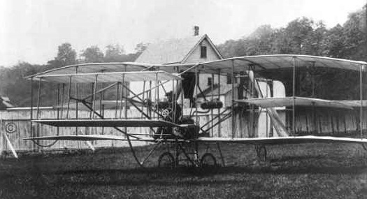
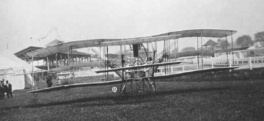
After years of effort, Miss E. Lillian Todd, of No. 131 West Twenty-third street, realized her ambition on Nov 7, 1910, when she had the pleasure of seeing a biplane, the work of her hands and brain, fly across the Garden City aviation field.

Designed and built by E. Lillian Todd and first flown by Didier Masson over the Garden City aviation field in Long Island during November of 1910.

Miss Todd was well known at the time, and her 1910 Biplane, powered by an eight cylinder 60 hp Rinek engine, was the first successful aeroplane built by an American woman. She then tried to get an engine, but met with repeated defeat, as the engines which she tried were not suitable. Finally a modified Rinek motor was declared satisfactory. Todd is told to have designed and built three full-size aircraft; her first – an engineless machine – in 1906.

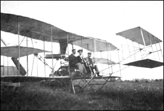
A good sized crowd was on hand to witness the first attempt to fly the biplane. Mr. Didier Masson was the aviator. He ran the machine across the ground, then went to the air for twenty feet and made a turn at the far end, returning to the starting place, where he was enthusiastically received by Miss Todd and the crowd.

Todd in her plane with Didier Masson

Miss Elizabeth L. Todd has entered the lists as a competitor in several long-distance flights and she has her mechanicians at work in her aerodrome at Hempstead Plains on three machines she designed. She has made several flights and has learned to manipulate her planes and her engines in masterly style.

E. L. Todd at the Controls
Probably Sept., 1909

Todd Special

Built first as a Wittman Tailwind, Edward Todd rebuilt the aircraft in 1963 with the wings lowered and the engine raised. Registered N11Q, it was first flown in June 1963.

Engine: Lycoming O-290G, 125hp
Wingspan: 22’0″
Length: 19’6″
Useful load: 621 lb
Max speed: 170 mph
Cruise speed: 160 mph
Stall: 60 mph
Range: 805 mi
Seats: 2