In 1909 Chapiro designed and built in France a biplane.
Span: 39’4″
Length: 29’6″
In 1909 Chapiro designed and built in France a biplane.
Span: 39’4″
Length: 29’6″
As early as 1894, inspired by the work of the German glider experimenter Otto Lilienthal, Chanute began to design gliders capable of carrying human beings into the air. Anxious to provide employment for younger engineers and flying machine enthusiasts, he began contracting for the construction of several gliders.
The first thing done, after some models, was to build a kite, in order to test the stability of the proposed gliding machine. This was called the “ladder kite,” from its resemblance to a step-ladder in one of its postures, for it was so constructed as to allow grouping its surfaces in various ways. This kite proved exceedingly stable, flying in gusty winds. Then the construction of a similar machine was begun. which was capable of carrying a man, but first Mr. Herring rebuilt a machine, previously tested by him in New York, somewhat similar to that of Lilienthal, so that the known should be tested before passing to the unknown.
Chanute selected the sand dunes along the southern shore of Lake Michigan as the perfect place to test his creations. The area was close to Chicago. The little train station at Miller, Indiana served as an entry point into Dune country. The area offered a number of other important advantages, including steady winds, dunes from which a glider could be launched in any direction, an abundance of sand for soft landings, and, Chanute hoped, relative isolation.
Chanute and his four assistants pitched their tents on a spot within the present city limits of Gary, Indiana, on June 22, 1896. Augustus Herring, the most experienced member of the group, had brought a glider based on the standard Lilienthal monoplane design. William Avery, a Chicago carpenter, had constructed a multi-wing glider designed by Chanute, while William Butusov would attempt to launch his own glider, the Albatross, down a wooden ramp. Dr. James Ricketts, a Chicago physician with “a slack practice and a taste for aeronautics,” would cook for the group and provide emergency medical service as required. Chanute’s dogs, Rags and Tatters, rounded out the party.
Herring and Avery did most of the flying. The Lilienthal glider proved to be a disappointment. After abandoning this Lilienthal form of machine, the experimenters in the sand dunes next tested the machine built after the fashion of the ladder kite which had proven so steady in the air.

It consisted of six pairs of wings, superimposed and trussed together, pivoted at their roots upon a central frame, the lower chord of which was spread open to receive the man at the center. Here he was expected only to move for the purpose of steering, the stability to be maintained by the movements of the wings above him, which swung on their pivots back and forth, restrained by rubber springs, when the wind struck one side more than the other, or changed the center of pressure fore and aft. It will be seen that this is just the reverse of the first method tested, in which the man moved and the wings remained fixed. This wing movement took place as expected, but it was very soon found that there was an essential difference between the support from the wind derived from the same arrangement when flown as a kite, at an angle of incidence of 30 to 40 degrees, and when flown as a gliding machine, at an angle with the wind of three or four degrees, which is the most favorable for reducing the total resistance to a minimum. It was found that at very acute angles the moving air was deflected downward by the front wings, so that the support under all the following wings was greatly diminished, and that the apparatus was inefficient when its surface was considered. This had been expected, from prior experiments, and the frame had been designed so that the grouping of the wings could be readily changed. Then began an interesting and instructive evolution. The grouping of the wings was gradually changed, through six permutations, each being guided by gliding flights and by releasing bits of featherdown in front of the machine, and watching the paths of the air currents which swept past the wings. The result of this evolution was to change greatly the outward appearance of the apparatus while retaining the same general principle.
Chanute’s glider, featuring multiple sets of wings that could be arranged in various configurations, was more interesting, covering distances of from 50-116 feet through the air. The group returned to Chicago on July 4. They would spend the next month repairing their various craft and building a new glider featuring three wings set one on top of the other, all linked together with a truss of the sort that Chanute had employed in constructing railroad bridges. Herring was apparently responsible for the cruciform tail.
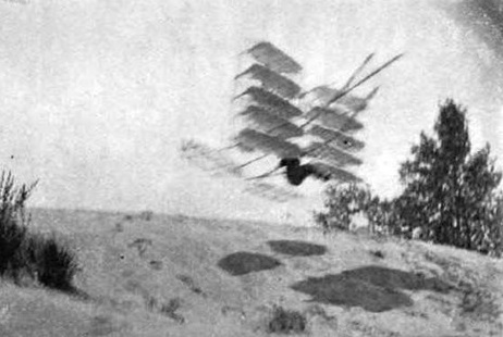
The improved arrangement as seen from one side in flight. It will be noticed that no less than five of the six pairs of wings have been superimposed at the front, and trussed together. That the operator is within and under them, and that a single pair of wings remains at the rear to serve as a tail. This tail was flexible and vibrated up all down in flight when the angle of incidence varied in consequence of the back and forth movements of the pivoted front wings.

About two hundred glides were made, in winds of 13 to 22 miles an hour, on a descending course of about 1 in 4 (14o), the longest flight being 82 feet from a height of about 20 feet. There was, however, undue friction in the wing pivots, thus retarding their automatic action, so that the operator had to move two or three inches, as against some 15 or 18 inches on the previous machine, and there being some further defects in the spacing of the wings, both vertically and horizontally, it was determined to rebuild the machine with the practical information thus obtained.
Camp was accordingly broken up early in July, with the conviction that more had been learned during this two weeks of experiment with full-sized machines than had previously been acquired during about seven years of theoretical study and experiments with models. The equipment was returned to Chicago, where three machines were constructed, and the five men returned to the Dunes on August 21, 1896, establishing a new camp some five miles down the beach from their original site.

The multiple-wing machine as reconstructed consisted of the same wings and of a new frame, and instead of ordinary pivots, there were ball bearings at the ends of vertical wooden posts to which the roots of the wings were attached, the latter being all trussed together, with vertical posts and diagonal wire ties, this being probably the first application which has been made of the Pratt truss to flying machine design. The frame was all made of spruce, the surfaces were of Japanese silk varnished with pyroxelene; the complete machine weighed 33 1/2 pounds, the supporting surface at the front was 143 1/2 square feet, including a concave aerocurve over the top, added when the front wings were cut down to four pairs, and the rear wings or tail measured 29 1/2 square feet in area. With this arrangement a great many glides were made, with the result of more than doubling the lengths previously attained, of reducing the angle of flight to 1 in 5, and of diminishing the required movements of the operator to one or two inches in preserving the equilibrium.
The Seventh Form Multiple-Wing Chanute-Avery Multiple-wing Gliding Machine “Katydid” was built by Chicago carpenter William Avery to the specifications of Octave Chanute based on the principles of the Pratt truss.
The photographed above is with Chanute during its extensive testing by Avery from the dunes on the shores of Lake Michigan at Miller Beach, Indiana, near Chicago in September of 1896; the Katydid was so named because of its insect-like appearance and made some two hundred glides that summer.
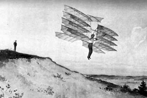
It might have been preferable to omit the aerocurve over the top, and to have placed all the supporting surface in the pivoted wings at the front. This aerocurve was added to save the expense of rebuilding the old wings, and this saving proved to be a mistake. The wings were so far racked and distorted by their prior service that they did not support alike and did not balance the weight properly, and thus the results obtained with that machine were inferior.
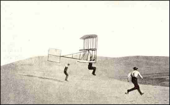
After some disappointing test flights, Chanute ordered the bottom wing removed from the new glider, producing a biplane design.
With that modification complete, Herring and Avery were soon making repeated flights of over 200 feet in length, occasionally traveling as far as 350 feet through the air. By the time the group broke camp for good on September 25, 1896, they had completed several hundred flights with the biplane. For the moment, the little craft was the most successful heavier-than-air flying machine in the world.
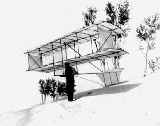
The next full-sized machine which was built consisted of a single intersection Pratt truss carrying the surfaces, to which was applied a regulating mechanism designed by Mr. Herring. This truss will safely support 300 or 400 pounds applied to the arm bars at the center. In calculating its proportions a basis has to be adopted which is the reverse of that which obtains in the calculation of bridges, for the support, or air pressure, has to be considered as uniformly distributed, and the load has to be figured out as concentrated at the center. It may be mentioned in this connection that one practical difficulty found has been in devising some method of adjustable connection between the vertical posts and the diagonal ties. The latter are from two to five hundredths of an inch in diameter, and it is not practicable either to cut a screw upon them for a nut, nor to apply a sleeve nut or a turn buckle. Perhaps some engineer will suggest a better device than the loop heretofore used, which is made by twisting the wire back upon itself, and which is not adjustable.
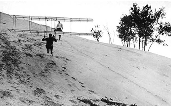
The regulating mechanism took care of the equilibrium fore and aft and diminished the effect of the side wind gusts which were then easily overcome by slight side movements of the operator. Towards the last amateurs were permitted to try it under instructions. They made fair glides in safety. One or two cruises by newspaper reporters, and another by a novice, who was picked up by the wind and raised some forty feet into the air, but who landed almost in his tracks as gently as if he had only fallen from the height of a chair.
With this apparatus several hundred glides were made, varying in length from 150 to 360 feet, at angles of descent of 7 1/2 to 10 degrees, at a height of ten to twenty feet above the ground, but it was not uncommon for the machine to sail forty or fifty feet above the ground, and during the six weeks occupied with the experiments, not the slightest accident occurred either to the operators or to the machines. The whole apparatus spread 134 square feet of supporting surface, weighed 23 pounds, and thoroughly supported the weight of a man at speeds of about 23 miles an hour.

The 1896 biplane tested on the Indiana Dunes proved to be a key step on the road to the invention of the airplane. Herring continued to experiment with the design on his own over the next five years. Chanute’s publication of the plans and specifications for the glider helped to spark a renewed interest in flight both in America and Europe. In May 1900, Octave Chanute received a letter from Wilbur Wright. “Afflicted with the belief that flight is possible to man,” the Wrights had designed a glider of their own. “In appearance, Wilbur noted, “it is very similar to the ‘double-decker machine with which the experiments of yourself and Mr. Herring were conducted in 1896-97.”
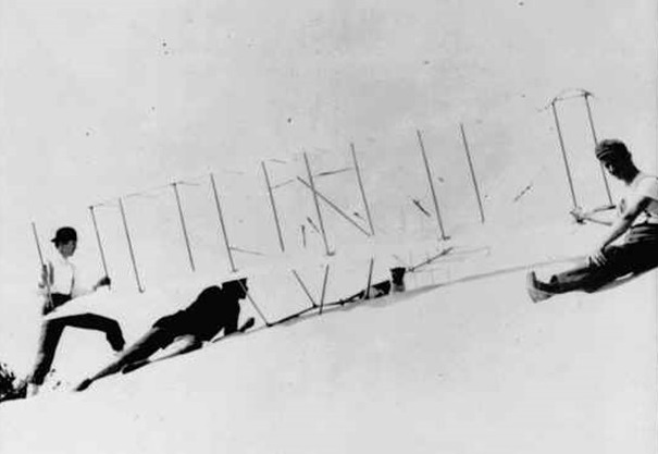
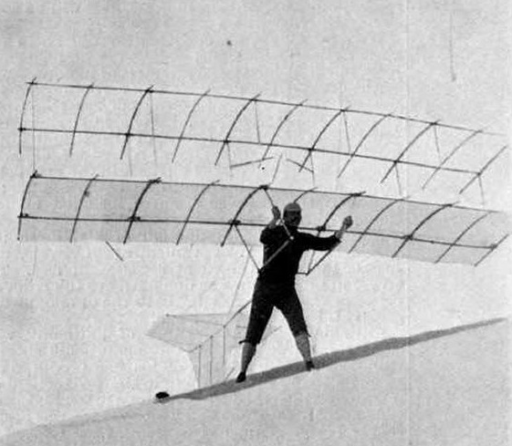
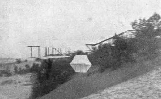
Chanute biplane
First flight: 1896
Wing span: 4.9 m / 16 ft
Length: 1.2 m / 4ft
Weight: 14 kg / 31 lb
The Chandelle Mk IV is an American ultralight aircraft that was designed by Nile Downer and produced by Chandelle Aircraft. The aircraft was supplied as a kit for amateur construction.
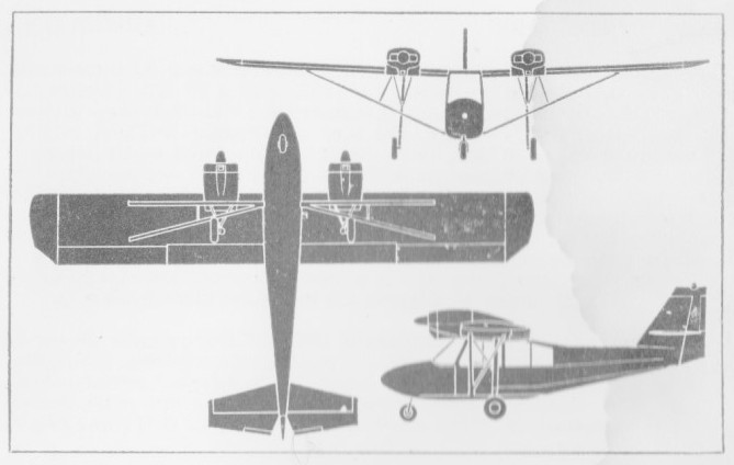
The aircraft was designed to comply with the US FAR 103 Ultralight Vehicles rules, including the category’s maximum empty weight of 254 lb (115 kg). The aircraft has a standard empty weight of 243 lb (110 kg). It features a strut-braced high-wing, a single-seat, open cockpit, tricycle landing gear and a single engine in pusher configuration.
The aircraft is made from bolted-together aluminum tubing, with the wings and tail surfaces covered in Dacron sailcloth. Its tapered planform, single-surface, 30.5 ft (9.3 m) span wing is supported by both lift struts and jury struts. The wing features 3/4 span ailerons. The pilot is accommodated in an open seat without a windshield. The tail surfaces are mounted on tubes that travel beside and below the pusher engine and propeller. The tricycle landing gear features main gear suspension.
The Mark IV appeared just before the collapse of the US ultralight market in 1984 and so few were produced or sold.
Chandelle Aircraft Mk IV
Engine: 1 × Cuyuna UL II-02 twin cylinder, two-stroke, 30 hp (22 kW)
Propeller: 2-bladed wooden
Wingspan: 30 ft 6 in (9.30 m)
Length: 17 ft (5.2 m)
Height: 8 ft 7 in (2.62 m)
Wing area: 153 sq ft (14.2 sq.m)
Empty weight: 243 lb (110 kg)
Gross weight: 500 lb (227 kg)
Fuel capacity: 5 U.S. gallons / 19 lt / 4.2 imp gal
Maximum speed: 59 mph / 95 km/h / 51 kt
Cruise speed: 45 mph / 39 kt / 72 km/h
Stall speed: 23 mph / 20 kt / 37 km/h
Never exceed speed: 75 mph / 65 kt / 121 km/h
Rate of climb: 700 ft/min / 3.6 m/s
Crew: one

In early 1907 Joseph Chantraine was awarded patent No. 198,483 for his “Aéromobile”. This aircraft was a monoplane controlled by means of a joystick and driven by three strong bicycle wheels driven by chains. The wings were made of bamboo covered with light tarpaulin.
His machine was constructed in 1907 in Kortenberg. The available picture of the machine shows a little monoplane with two tractor propellers driven by a single engine possibly via rods.
Chantraine was incapable of making test flights so he asked an 18-year old pupil of a technical school in Brussels, Edouard Tollet, to attempt them instead. Tollet is seen in this photo at the left wing tip, while Chaintraine is in the center. Tollet made a flight which was not successful as the machine crashed and was heavily damaged, and he himself slightly injured. The machine flew twice, but on its second flight it fell down in a tree.
Chantraine acquired several patents in Belgium, France and the UK, however he died in 1910 at the early age of forty. Tollet followed a career in aviation, serving in WWI and continuing as a member of the Belgian aviation service until pensioned as a high-ranking officer in 1946.

The inventor of the joystick, Joseph Chantraine, lived and worked in Kortenberg in the Belgian province of Flemish Brabant. Chantraine patented several inventions and in 1906 patented a ballpoint pen, and the same year patented a classifier system.
Joseph Chantraine was an engineer and a university professor. In early 1907 Joseph Chantraine was awarded patent No. 198,483 for his “Aéromobile”. This aircraft was a monoplane controlled by means of a joystick and driven by three strong bicycle wheels driven by chains.
Joseph Chantraine died on June 8, 1910 at the early age of forty. He was probably very engaged in aviation as his villa in Kortenberg was named ‘L’Aérocottage’.
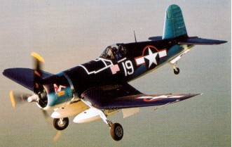
A design team headed by Rex Biesel and lgor Sikorsky set out to tackle a February 1938 US Navy requirement for a single seat carrier borne fighter; the challenge being to build the smallest possible fighter around the most powerful air cooled engine then under development.
Such a huge propeller was required for the world’s first 2000 horse power engine a Pratt and Whitney 18 cylinder two row Double Wasp radial that the team followed Junker’s lead in using an inverted gull wing to provide sufficient ground clearance for the 4.1 metre (13 feet 4 inch) three bladed Hamilton constant speed propeller.
The wing design also enabled the use of short and strong oleo legs capable of withstanding operational carrier landings and, as an added benefit, the wings folded from the lowest part of the wing to provide a low overall height when the wings were in folded configuration. On retraction the gear rotates through 89 degrees and then folds backwards into the wing. As the weight is taken off the oleos the legs are prevented from extending by cables. The distinctive gull wing shape was used to allow the very large diameter propeller to be used and still keep a relatively short strong undercarriage for aircraft carrier operations.
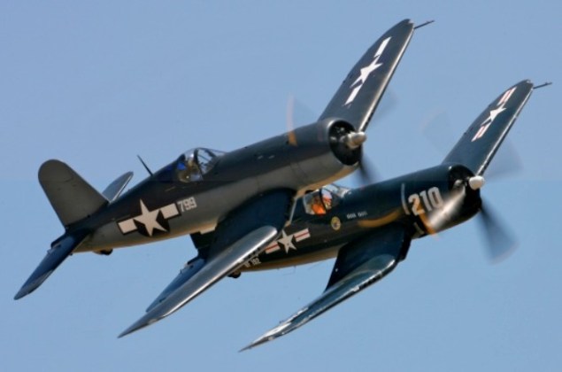
In 1938 the Navy became involved in three new fighter projects the Grumman XF5F 1 and similar USAAF XP 50, the Bell XF1 1 and the Vought XF4U 1 (V-166A). The long term intention was to bolster the Navy’s sagging carrier forces whose squadrons flew the Grumman F3F 2 biplane fighter harking back to the mid1930s.
Chance Vought F4U / F2G Corsair Article
Chance Vought won the contract and the project was under way. The Corsair’s first test flight on 29 May 1940 the delay being largely the result of engine development problems resulted in the elevator tabs tearing loose during a high frequency oscillation just above 200 mph. Lyman Bullard Jnr, Chance Vought test pilot, landed the prototype 1443 successfully despite the damage to the control surfaces. On 1 October 1940 the aircraft recorded a ground speed of 404 mph, the first single-engine US military aircraft to exceed that speed (Lockheed P-38 was the first US aircraft).

Some 12,681 of them were built over the following 10 years.
US Navy pilots were enthusiastic about the aircraft’s rate of climb and speed but had reservations about inadequate forward vision during takeoff and landing, a marked tendency to torque stall in carrier approach configurations and a lack of directional stability following touchdown. There appears no doubt that, had the necessity for a high speed carrier borne fighter not been paramount, the Corsair could well have become an also ran. Instead the US Navy issued a contract for 584 units and the first production example flew on 25 June 1942.
The production F4U-1 (V-166B) machines featured the cockpit moved rearwards to make room for the fuel tankage, shifted from the wings to make way for six .50 Browning machine guns, and the even further impaired forward view plus the still unsolved directional instability after landing and the threat of torque stall on approach led the US Navy to decide that the Corsair was unsuitable for combat in the hands of average carrier pilots.
Instead the production delivery (the first -1 in June 1942) was re allocated to the US Marines for land based operations; the first unit (VMF124) flying its first operational mission from Guadalcanal on 1 February 1943 and, within six months, all Marine squadrons in the Pacific had been equipped with the Corsair.
The Marine Corsairs provided immediate protection for the bombing raids on Rabaul, usually flown at 20,000 feet with the P-40s flying below and the P-38 Lightning as top cover above 30,000 feet.
First flying on 25 June 1942, piloted by Boone T Guyton, some 688 F4U-1s (V-166B) were built before a bubble canopy and undercarriage modifications led to the F4U-1A model.
The 1942 F4U-1A was an improved F4U-1 with a P&W R-2800-8, and later 2250hp -8W engine. 688 were built, including 360 to the Fleet Air Arm as the Corsair II and 173 to the RNZAF as Corsair. The wingtips were shortened 6″ and squared-off to fit the lower ceilings of the British carrier hangar decks, and the cockpit was re-arranged with British radio, new seat and harness, other mods.
By August 1943 both Goodyear (FG-1 – fixed wing) and Brewster (F3A1) had joined Chance Vought in the production of Corsairs. Goodyear built FG 1Ds were distinguished from the F4U 1D by clear blown canopies, underwing rocket launching stubs and starting courtesy of a electric battery cart rather than cartridges.
It was at this time that the British Royal Navy gladly accepted 95 early F4U-1 models, designated Corsair Mk.1s, for carrier service. F4U-1B was the temporary production designation for 1943 exports for Great Britain but was never applied in deference to aircraft taken from USN production batches. About 605 went to the Fleet Air Arm as Corsair I, and 370 for the RNZAF. The Royal Navy, after clipping eight inches off each wing to enable the fighters to be fitted underneath the flight deck, operated the Corsair in the European theatre alongside their Fleet Air Arm Wildcats, Hellcats and Seafires.
A total 4,102 of all F4U-1 variants were built. Modified with water injection, raised cockpit, and canopy redesign after the first 1,550 units.

A notable operation was the attack by HMS Victorious-based Corsairs on the German pocket battleship Tirpitz in Kaa Fjord. By April 1944 Royal Navy Corsairs were in operation in the Pacific.
The XF4U-3 of 1946 was an experimental high-altitude fighter version with twin turbochargers. Three prototypes for the Goodyear FG-3 were conversions from F4U-1As 02157, 17516, and 49664.

One F4U-1 was modified in 1944 to a XF4U-3B ground-attack fighter powered by a P&W R-2800-16 with an external turbo-supercharger.
In 1943 five XF4U-4 prototypes with 2450hp R-2800-18W engines were built, 80759 to 80763, plus two were modified from F4U-1A as XF4U-4X, 49763 and 50301, one of which tested with Aeroproducts’ twin counter-rotating props in 1945.
Two hundred F4U-1A were modified from 1943 to F4U-1C close-air-support version with four 20mm cannons. These first saw combat at Okinawa.

The US Navy accepted the F4U-1D in April 1944 for carrier trials – the new designation covering a multitude of modifications such a full plexiglass canopy to replace the metal braced flat sided canopy of the -1, a higher placed pilot’s seat for improved visibility, longer stroked oleos, modified aileron mechanism to improve control at low speeds, and more power from a water injected P&W R2800-8W. The Corsair remained a difficult aircraft for US carrier operations.
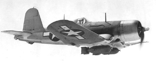
Also built as the Goodyear FG-1D the fighter/bomber was equipped with 160-gal drop tank, bomb racks, under-wing rockets. 150 of the F4U-1D were built, going to the Fleet Air Arm as Corsair II and 190 to the RNZAF as Corsair.
After six months the US Navy cleared the Corsair for combat duty, the first operation unit (VF17) flying from New Georgia as a shore-based squadron. It was not until late in 1944 that a Corsair-equipped Marine squadron (VMF124) joined the USS Essex and proved highly successful against Kamikaze attacks. By the end of the Okinawa campaign all US Navy carriers were equipped with Corsairs.
A 1943 night-fighter version, the XF4U-2 was operated by an American specialist unit flying out of Munda on New Georgia with two machine guns removed and an early mark of airborne interception radar (an APS-4) mounted on the right wing leading edge and an autopilot fitted. The XF4U-2 was a conversion from F4U-1 02153.

Thirty-two were converted from F4U-1s by NAF, and two from F4U-1As in the field.
Charles Lindberg, acting as a civilian technical representative for United Aircraft in the Pacific combat area, pioneered the process of doubling the Corsair bomb load from 2000 to 4000 lbs.
Re-introduced in the early -1D were wing leading edge fuel tanks, small 62 gallon unprotected units outboard of the gunbays. Most, later F4U-1Ds differed in having the outboard-wing leading edge fuel tanks deleted and hard points for bombs or external fuel tanks installed under the centre section.
The RNZAF was issued with 424 of these aircraft; thirteen squadrons eventually used the aircraft. Corsairs in RNZAF service did have their problems – predominately centering on the complex hydraulic system, the engine, bombracks, brakes, and ailerons – the main spar of which rotted out after about a year due to water. The F4U-1 wing tanks on the leading edges wept petrol through rivet holes after a few months service due to the vibration of the Brownings, and caused these tanks to be sealed off. This was the primary difference between the F4U-ls and the -1Ds in the RNZAF. FG-1D’s were similar to F4U-1Ds but introduced a clear blown pilot canopy and rocket launching stubs underwing.
With dive brakes extended, the airspeed would stabilise at about 300 knots, but in the clean condition, the aircraft was permitted to indicate 420 knots between 7,500 feet and sea level, which was 470 knots true airspeed.
As early as 1941 the US Navy had requested better high altitude performance from Chance Vought and, in July 1944, the F4U 4 with an uprated Pratt and Whitney R2800 18W engine with water/methanol and driving a four bladed propeller, and new cowl design, made its first test flight. The 4 proved to have a top speed of 425 mph (680 kph) at 28,000 feet, compared with the 1 of 392 mph (630 kph) at 24,000. The first F4U 4 went into service in January 1945, being operated until the end of the Korean War as a carrier borne fighter bomber. Production was also scheduled by Goodyear as FG-4, but the contract was cancelled and none were built.

In 1945 287 F4U-4B were scheduled for the Fleet Air Arm as Corsair I, but were cancelled with the end of hostilities.
Two-hundred and ninety-seven of the 1945 F4U-4C were built, with 20mm cannons.
The 1946 V-354 was a two-place trainer conversion of F4U-1 for Navy evaluation but, with the impending jet age, no contract was offered. USN mark 49763 was possibly assigned, which listed as an F4U-4XA.
Possibly only one of the 1946 F4U-4E night fighter with APS-4 radar was built, and the single F4U-4K was a radio-controlled target.
There was one F4U-4N in 1946 which may have been an upgrade of an F4U-4E with a wing-mounted APS-6 radar.
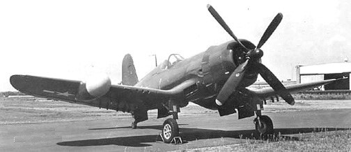
About 1946, nine aircraft were modified to F4U-4P Photo-recon aircraft.
The F4U-5 was developed to meet a high altitude fighter requirement for the United States Navy in 1947. It differs from the F4U-1 and FG-ID series in a number of respects; a four bladed propeller, twin cheek inlets on the cowling for the side mounted superchargers, metal covered outer wing rear panels (instead of fabric aft of the main spar) to reduce drag and a slightly more bulged canopy to improve rearward vision. The uprated 2850 hp R-2800-32W engine was titled downward 2.75′ to improve stability and forward vision.
Although most contracts for fighters were cancelled at the end of WW2 the Corsair remained in production. Only 5 F4U-5 were built in 1947, 61 in 1948, and 69 in 1949.

The last of 14 F4U-5N was delivered to the US Navy on 22 October 1951. The winterised F4U-5NL had a production run of 100 during 1950-51.
The F4U 5N night fighter variant differs significantly from the 1 model in having different engines, propeller, cowls and exhaust system as well as a later style canopy with a raised section aft.
The XF4U-5 first flew on 4 April 1946 and introduced a new engine. The wings were totally skinned in metal and ailerons were given spring tabs. Heaters were provided for the windshield, gun bays and pitot head. Three were converted from F4U-4. A total of 223 production F4U-5 were built from 1946, featuring all-metal wings.
The 1947 F4U-5P was an armed photo-recon version. Thirty were built: 122167 to 122206.
Similar to the F4U-5, a low altitude version with the R-2800-83W engine and increased armour was originally designated F4U-6, and later AU-1. Built in 1951, the prototype, 124665, first flew on 29 December 1951.

Built from 1952 as a USMC low-altitude fighter and ground support aircraft featuring a narrow cowling, wing oil coolers move to inside fuselage; added armor, and bomb/rocket wing racks. The F4U-6 designation was never applied; redesignated AU-1 instead. 111 went to the USMC squadrons in Korea (129318-129417, and 133833-133843). Veteran aircraft were overhauled and sold to the French AF in 1955.
90 F4U-7 were built in 1952 for the French AF in Indochina. The last prop-driven fighter built in the US.
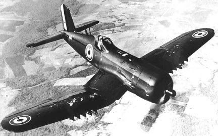
Forty-four F4U-5N night fighters were built from 194, 124665 to 124709. Some 75 winterised F4U-5Ns were built for service in Korea as F4U-5NLs with wing and empennage boots, propellor de-icer shoes and windshield de-iceing, 124504 to 124560, and 124710 to 124724. The F4U-5N had the APS-19A radar. The last operational Corsairs in United States Navy services were withdrawn in December 1955 and the last of the Reserve Squadron F41J-5s were retired in June 1957.

During the Korean War the US Navy used 27 F4U day squadrons. In addition VC-3 flew F4U-5NL night fighters with attachments on every carrier.
The F2G-1 was the “Sprint” Corsair developed by Goodyear in 1945 using the Wasp Major engine. Only 17 were built. The Goodyear F2G is distinguishable from the Chance-Vought Corsair by having a clear blown canopy.
The last Corsairs to see actual air to air combat were those of the Honduran Air Force during the 11 19 border war between Honduras and El Salvador. On 17 July 1969 a Honduran pilot flying an F4U 5 shot down a P 51D Mustang and two FG 1 Corsairs. The Honduran Corsairs were subsequently sold to collectors in the USA.
The aircraft was used by the French naval air arm during the Suez operations in 1956.
In production from 1941 to 1953, a total of 12,571 were built. Final production on 26 January 1953 ended the longest production record of any airplane built up to that time.
The combat record in the Pacific was 189 F4Us were lost both in combat and non-combat (but excluding training) in destroying 2,140 Japanese aircraft.
Variants:
XF4U-1 – Prototype
VS-317 Modifications on XF4U-1
F4U-1 – Production, seat moved aft 3 ft
VS-321 Modifications on F4U-1
VS-323 F4U-1 with Wright R-3350 engine
VS-324 Modifications on F4U-1
VS-325 Modifications on F4U-1
F4U-1B – Production for British Royal Navy
F4U-1C – Four 20 mm cannon
F4U-1D – Twin pylons for fuel tanks or bombs
F4U-1P – Photographic equipment
XF4U-2 – Special night fighter, radar gear
F4U-2 – modified by Navy as night fighter
VS-331 XF4U-3 – projected turbosupercharger version
XF4U-4 – new engine, propeller, cowling, carberator
V-334 F4U-4 – basic production version
V-336 F4U-1WM (F4U-1 with P&W R-4360 Wasp Major)
V-342 F4U with E engine
F4U-4B – Produced for Royal Navy
F4U-4C – Four 20 mm cannon
F4U-4N – night fighter version
F4U-4P – Photographic version
F3A-1 – Manufactured by Brewster
F3A-1D – Mrewster model of F4U-1D
FG-1 – Manufactured by Goodyear (F4U-1)
FG-1D – Goodyear version of F4U-1D
FG-1E – Radar equipped
FG-3 – Turbosupercharger version
F2G – 3000 hp engine version
XF4U-5 – New P&W engine, supercharger
V-351 F4U-5 – R-2800-32(e) engine, max speed 480 mph
V-354 F4U two seat advanced trainer
V-376 F4U for Perú
V-361 F4U-5 variant
F4U-5N – Night fighter version
F4U-5P – Photographic version
F4U-5NL – Winterised version for Korea
AU-1 – Low altitude attack version, Korean war
F4U-7 – Same as F4U-4 for French Navy
Specifications:
Vought F 4 U Corsair
Engine: Pratt & Whitney R 2800 18W Double Wasp, 2416 hp
Length: 33.661 ft / 10.26 m
Height: 14.764 ft / 4.5 m
Wingspan: 40.912 ft / 12.47 m
Wing area: 313.986 sqft / 29.170 sq.m
Max take off weight: 14672.1 lb / 6654.0 kg
Weight empty: 9205.9 lb / 4175.0 kg
Max. speed: 388 kts / 718 km/h
Service ceiling: 41503 ft / 12650 m
Wing load: 46.74 lb/sq.ft / 228.00 kg/sq.m
Maximum range: 1356 nm / 2511 km
Range: 873 nm / 1617 km
Crew: 1
Armament: 6x cal,.50 mg (12,7mm), 2x 454kg Bomb./ 8x 5″-Rocket
XF4U-1 / V-166A
Engne: P&W XR-2800-4, 1850hp
Prop: 14′ three-bladed
Wingspan: 41’0″
Length: 31’11”
Useful load: 1852 lb
Max speed: 405 mph
Cruise speed: 190 mph
Stall: 73 mph
Ceiling: 35,200 ft
F4U-1 / V-166B
Engine: Pratt & Whitney R-2800-8(B) Double Wasp, 2000 hp
Wingspan: 40 ft 11.75 in / 12.48 m / British 39 ft 7 in
Length: 33’4″
Useful load: 3057 lb
MAUW overload: 14,000 lb.
Max speed: 417 mph
Top speed: 392 mph (630 kph) at 24,000 ft
Cruise speed: 182 mph
Stall: 87 mph
Range: 1015 mi
Ceiling: 36,900 ft
F4U-1A
Engine: P&W R-2800-8, later -18W Double Wasp, 2450 hp
Wingspan: 40 ft 11.75 in / 12.48 m / British 39 ft 7 in
Length: 33 ft 8.25 in / 10.27 m
Empty weight: 8873 lb / 4025 kg
MAUW: 14,000 lb / 6350 kg
Max speed: 395 mph / 635 kph
ROC: 2890 fpm / 880 m/min
Service ceiling: 37,000 ft / 11,280 m
F4U-1D
Engine: Pratt & Whitney R2800-8W Double Wasp, 2000 hp.
Length 33.3 ft. (10.15 m.).
Wing span 41 ft. (12.5 m.).
Weight empty 8,980 lb. (4,070 kg.).
Max wt: 5,465kg (12,039 lb).
Crew 1 pilot.
Armament 6 x 0.50 in. machine guns, 2 x 1,000 lb. (450 kg.) bombs; or 8 x 5 in. (13 cm.) rockets.
Max speed 417 mph (670 kph).
Range 1,015 miles (1,630 km.).
F4U-2 (Naval Aircraft Factory)
Useful load: 2276 lb
Max speed: 381 mph
Cruis speed: 187 mph
Stall: 82 mph
Range: 995 mi
Ceiling: 33,900′
XF4U-3
Length: 33 ft 4in 4
Max speed: 412 mph
Cruise: 180 mph
Stall: 83 mph
Range: 780 mi
Ceiling: 38,400 ft
XF4U-3B
Engine: P&W R-2800-16
XF4U-4
Engine: R-2800-18W, 2450hp
F4U-4
Engine: Pratt & Whitney R-2800-32(E) Double Wasp, 2850 hp
Prop: four-blade
Wingspan: 40 ft 11.75 in / 12.48 m / British 39 ft 7 in
Length: 33 ft 8.25 in / 10.27 m
Useful load: 3215 lb
Max speed: 446 mph
Top speed: 425 mph (680 kph) at 28,000 ft
Cruise speed: 215 mph
Stall: 89 mph
Range: 1005 mi
Ceiling: 41,500′
Armament: six .50 guns, eight wing rockets
Bombload: two 1000 lb
XF4U-5
Engine: Pratt & Whitney R2800-32W Double Wasp, 2850 hp.
Engine: P&W R2800-8W Double Wasp 18-cylinder radial, 2,000 hp
Wing span: 41’0”
Length of 33’4.5”.
Sevice ceiling: 37,000 ft.
Range: 1015 sm
Armament: 4 x 20mm
F4U-5
Engine: Pratt & Whitney R-2800-8(B) Double Wasp, 2000 hp
Wingspan: 40 ft 11.75 in / 12.48 m / British 39 ft 7 in
Length: 33 ft 8.25 in / 10.27 m
Empty weight: 9900 lb / 4490 kg
MAUW: 15,079 lb / 6840 kg
Max speed: 462 mph / 744 kph
ROC: 4800 fpm / 1463 m/min
Service ceiling: 44,000 ft / 13,400 m
Range: 1120 mile.
F4U-5N
Engine: Pratt & Whitney R2800 Double Wasp, 2850 hp.
Length: 34 ft 6 in
Max speed: 470 mph.
Range: 1120 mile.
F4U-5NL
Engine: 2,100 h.p. R2800
Span: 40 ft. l1.75 in
Weight: 13,300 lb.
Max. Speed: 470 m.p.h.
Armament: 4×20 mm. Cannon
F4U-6 / AU-1
Engine: Pratt & Whitney R-2800-83W Double Wasp, 2300 hp
Wingspan: 41’0″
Length: 34’1″
Useful load: 9144 lb
Maxspeed: 440 mph
Cruise speed: 184 mph
Stall: 83 mph
Range: 484 mi
Ceiling: 19,500′
F4U-7
Engine: Pratt & Whitney R-2800-18W Double Wasp two-stage superchargers, 2100 hp
Wingspan: 40 ft 11.75 in
Wing area: 314 sq.ft
Length: 34 ft 6.5 in
Height: 14 ft 9.25 in
Empty weight: 13,426 lb
Normal take-off weight: 13,426 lb
Fuel capacity internal: 195 gal
Fuel capacity external: 2 x 125 gal
Max speed: 450 mph at 25.000 ft
Armament: 4 x 20 mm cannon
Bombload: 4000 lb
F2G-1
Engine: Pratt & Whitney R-4360 Wasp Major, 3000 hp.
Wingspan: 40 ft 11.75 in / 12.48 m
Length: 33 ft 8.25 in / 10.27 m
FG-1D
Engine: Pratt & Whitney R-2800-8W.
AU-1
Engine: 2100 hp Pratt & Whitner R-2800-83WA
Wingspan: 40 ft 11.75 in
Length: 34 ft 6.5 in
Height: 14 ft 9.25 in
Wing area: 314 sq.ft
Empty weight: 10,418 lb
Loaded weight: 13,300 lb
MAUW: 19,398 lb
Max speed: 470 mph
ROC: 4800 fpm
Service ceiling: 40,000 ft
Range: 1120 mi
Armament: 4 x 20mm cannon
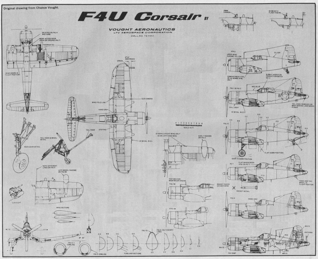

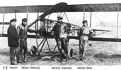
Lewis and Vought Corporation of Long Island, New York, built training aircraft in 1918 to designs of Chance M. Vought, for U.S. Army.
Lewis & Vought Corporation was renamed Chance Vought Corporation after First World War. From 1922-1926 produced UO-1 observation float biplanes (developed from VE-7/9) and FU-1 catapult fighter seaplanes for U.S. Navy, followed in 1927 by O2U observation landplanes for same customer, first of several Vought designs to bear the name Corsair. Moved to East Hartford, Connecticut, in about 1930, where until 1935 it continued the Corsair series with 03U observation biplanes and similar SU scouts, again for U.S. Navy.
Became Chance Vought Division of United Aircraft Corporation in 1934, initially continuing production at East Hartford of O3U/SU Corsairs. These were followed by Vought SBU two-seat scout-bomber, designed in 1932 and produced for U.S. Navy between 1935-1937.
In 1928, Boeing Airplane and Transportation Corporation went public and the stock sold quickly. Encouraged, Boeing formed the United Air¬craft and Transport Corporation, which included Boeing Airplane Company, Pratt & Whitney, Chance Vought, Sikorsky, Hamilton Propeller, Pacific Air Transport and Boeing Air Transport.
In 1934, Boeing was informed by the U.S. Government that he was violating the new antitrust laws. He resigned as chairman, sold out his stock and the corporation was divided into three new companies –United Air Lines to handle air transport, United Aircraft Corporation to take over the eastern manufacturing firms and Boeing Airplane Company to manage Western operations.
From 1936 concentrated primarily upon manufacture for the US Navy, major programs including the SB2U Vindicator scout-bomber, OS2U Kingfisher observation aircraft, and F4U Corsair single-seat naval fighter. Of the massive production of the wartime Corsair, which continued until 1952, Vought alone built more than 7,700.
Joined with Sikorsky Division of UAC in April 1939 to form Chance Vought and Sikorsky Aircraft Division of United Aircraft Corporation. Vought and Sikorsky were reconstituted in January 1943 as separate manufacturing divisions of UAC, so that Sikorsky could concentrate on helicopter development and Vought on combat aircraft, primarily the F4U and OS2U. On 1 July 1954 the company became independent of UAC, under the new name of Chance Vought Aircraft Inc. Chance Vought moved headquarters to Stratford, Connectictut. Vought-Sikorsky products at this time included the Sikorsky-designed VS- 43 and VS-44 flying-boats and the historic VS-300, the world’s first fully practical helicopter, from which the production R-4 and R-5 and later designs were developed. After the war, Chance Vought Aircraft Division moved to Dallas, Texas, in 1948-1949, and produced its first jet fighter for the US Navy, the F6U Pirate. Became Chance Vought Aircraft Inc. after becoming separate and independent from UAC on July 1,1954. Main product during this stage of its history was the unorthodox F7U Cutlass, in production 1952-1955 for the U.S. Navy. Deliveries began also in 1957 of the F-8 (originally F8U) Crusader, development and production of which continued as the LTV F-8 after further company metamorphoses into Chance Vought, Chance Vought & Sikorsky VS-44A Excalibur flying-boat, Chance Vought F7U Cutlass carrier-based fighter Corporation (from December 31,1960), and a merger on August 31,1961 with Ling-Temco Electronics Inc. to form Ling-Temco-Vought Inc.
Within the latter structure, Vought became, successively, the Aerospace Division of LTV, then Vought Aeronautics Company (Division of LTV Aerospace Corporation). Corsair II production under the name of the Vought Corporation. In 1964 in combination with Hiller-Ryan developed the XC-142A VTOL transport with swivelling wings. LTV Electro-systems developed the L450F quiet reconnaissance aircraft in 1970.
Since January 1, 1976 it has continued its activities as Vought Corporation, a subsidiary of the LTV Corporation.
Undertook considerable subcontract work, including on B-2 and many transport aircraft. Teamed with Argentina to propose Pampa 2000 for JPATS program, but not selected. Took name Vought once again in 1992. Became LTV Aircraft Products Group in 1986 and LTV Aerospace and Defense Company 1990. Following 1992 sale of 49 percent stock in LTV to Northrop and Carlyle Group, became Vought Aircraft Company, finally merging as a division of Northrop Grumman in 1994 after remaining stock purchased, becoming Northrop Grumman’s headquarters for its Commercial Aircraft Division.

A two-seat development of the Champion J-1, powered by a 125hp Lycoming O-290-G.
Skin-stressed laminated-fiberglass construction. First flown in 1963.
Engine: Lycoming O-290-G, 125hp
Wing span: 22’0″
Length: 17’4″
Loaded weight: 540 lb
Max speed: 160 mph
Cruise: 140 mph
Stall: 55 mph
Range: 40 miles
The J-1 Juptier was an all original design of Kenneth R. Champion and Horace Sackett in 1959 using wooden construction methods based on the Pietenpol Air Camper and new applications of fiberglass layups.
The J-1 is a low wing aircraft with conventional landing gear and a large bubble canopy. The wings are configured without dihedral. The fuselage uses a wooden geodesic airframe construction with steel secondary wing spars. The wing panels are covered with single seamless flat fiberglass panels that are bonded to the wooden wing ribs and spars. The leading edge is formed with fiberglass layered up in place. The same process is used on the elevators.
The J-1 Jupiter won the Outstanding Design award at the Experimental Aircraft Association airshow in 1959.
Variants
Jupiter K-2
Specifications:
Jupiter J-1
Engine: 1 × Continental A65, 65 hp
Propellers: 2-bladed MacCauley 65-60
Length: 17 ft 4 in (5.28 m)
Wingspan: 21 ft (6.4 m)
Wing area: 88 sq ft (8.2 m2)
Airfoil: NACA 4412
Empty weight: 627 lb (284 kg)
Gross weight: 910 lb (413 kg)
Fuel capacity: 16 U.S. gallons (61 L; 13 imp gal)
Max speed: 160 mph
Cruise speed: 96 kn; 177 km/h (110 mph)
Stall speed: 48 kn; 89 km/h (55 mph)
Rate of climb: 400 ft/min (2.0 m/s)
Range: 300 miles
Crew: 1
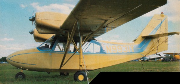
Manufactured by Champion Aircraft, the Lancer 402 was a multi-engine trainer from 1963.
With a fabric covered airframe and tandem seating, the Lancer had heel brakes and oleo-spring gear.
Powered by two Continential O-200A engines of 100 hp each, it sold for around US$12,500. The wing span was just over 34 feet, a wing area slightly over 170 sq.ft and an overall length of around 22 feet.
Landing gear tread is 9 ft 8 in. Steerable nose wheel is aluminium casting. Fuselage nose piece, top and cowl noses are fibreglass. Ground clearance of 44in at tail allows full stall landings. Cockpit with control wheel in front, stick in rear, is 28in wide. Rudder and stabiliser trim is via levers at the left of front and rear seats. Vertical trim tab on high, wire-braced tail provides for hands-off trim, even with the loss of one engine. Mixture and throttle controls are duplicated and located high on the cockpit left, with carb heat controls opposite back of front seat. Located at left wing root are fuel tank gauges selector switch for left tank, ignition switch, left engine starter and cockpit lights. Right wing root contains similar units for right engine plus two ammeters and electrical switches. Throttle mix controls hang from left side of cockpit.
The Lancer first flew in October 1961 and a number of changes were made, including the raising of the engine nacalles above the wing, and the first production model flew on 10 March 1963.
FAA certification was obtained in the spring of 1963, and the first production deliveries were made during the following summer, 36 being delivered by years end.
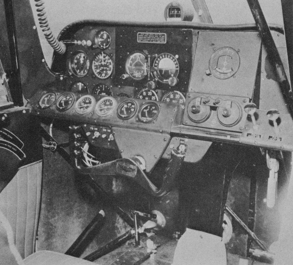
American Champion Aircraft Corporation held the Type Certificate Number A3CE for the Model 402.
Useable fuel is held in two 26 US gallon tanks. Climb and approach speeds are both 80 mph.
Up to 100 lb of baggage can be carried in a compartment behind the rear seat.
With two seats in tandem, Champion only manufactured 24 Lancers, featuring a control yoke for the front seat and a floor mounted stick in the rear.
Engines: 2 x Continental O-200A, 100 hp
Propellers: 69 in fixed pitch
Wingspan: 34 ft 5.5 in
Length: 22 ft 3 in
Height: 8 ft 1.5 in
Wing area: 170.22 sq.ft
MAUW: 2450 lb
Empty weight: 1790 lb
Useful load: 660 lb
Baggage capacity: 100 lb
Max structural cruise: 130 mph at 7500 ft
Cruise 75%: 120 mph
Cruise 65%: 115 mph
Range: 710 miles
Service ceiling; 12,000 ft
SL ROC: 642 fpm
Landing speed: 48 mph
SE min control speed: 73 mph
Stall clean: 64 mph
Seats: 2