Gloster Gamecock

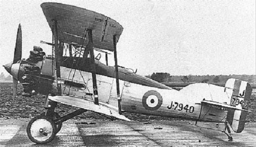
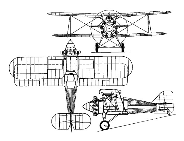
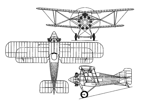
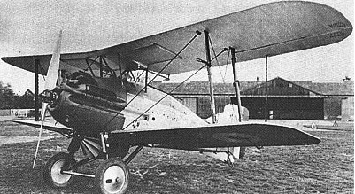
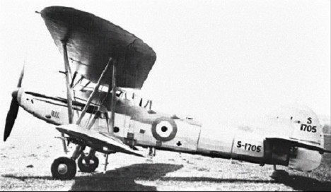
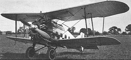
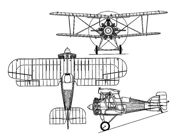
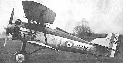
A development of the Gloster Grebe fighter, the Gamecock was initially to Specification 37/23, a re-engined variant of the Grebe using the new 398hp Bristol Jupiter IV radial engine. Of wooden construction with fabric skinning and retaining the then-standard armament of two synchronised 7.7mm Vickers guns. Ordered originally as the Grebe II in August 1924, the prototype Gamecock 1 (as it became titled) was delivered to Martlesham Heath for service tests on 20 February 1925. Trial reports were enthusiastic, resulting in an initial order for 30 production Gamecock Is machines in September 1925 powered by the 425hp Jupiter VI.
First to take delivery of the production Gamecocks was 23 Squadron RAF, at Hen¬low, in May 1926; followed by 3, 17, 32 and 43 Squadrons. Although designed for day fighting, the Gamecocks issued to 3 and 17 Squadrons were specially modified for night interception duties. During the next five years, Gamecocks were prominent in the many public displays organized by the RAF, and demonstrated the type’s manoeuvrability in many superb aerobatic exhibitions.
A further 60 Gamecock Is were built for the RAF (1925-27), one of these (unofficially known as the Gamecock III) at one time flying with a lengthened fuselage, new and enlarged fin-and-rudder assembly and narrow-chord ailerons.
Gamecock II

The Gamecock recorded a relatively high accident rate in service use; 22 having crashed within 19 months of its introduction to the RAF, and killing eight pilots. A variety of modifications were embodied progressively to eliminate the Gamecocks’ tendencies to spin abruptly and give wing flutter at high speed. Despite such characteristics, service Gamecocks quickly demonstrated their fast performance by tak¬ing the first three places in the 1927 Sassoon Cup Race for RAF fighter squadrons.
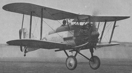
A developed version, the Gamecock II, with a steel-tube upper wing centre section, narrow-chord ailerons and a larger rudder, appeared in 1928. This was adopted by Finland, two pattern aircraft and a manufacturing licence being acquired. Fifteen Gamecock IIs were built for the Finnish air arm 1929-30 by the State Aircraft Factory (Valtion Lentokonenetehdas), these having the lengthened fuselage tested earlier in the UK by the so-called Gamecock III and being powered initially by the 420hp Gnome-Rhone Jupiter (IV) 9Ab or 9Ak and later by the 480hp Jupiter (IV) 9Ag. By 1929 licensed production of the design (renamed Kukko) began at Helsinki. One unit, Fighter Squad¬ron 24, continued to fly this variant from 1929 until 1935; while one Finnish Gamecock (GA¬46) remained in service until late 1944.

Though development of the basic Gamecock was undertaken, resulting in the Gamecock II and III, the latter saw no service use. In 1928 the Finnish government, having been much impressed by various dis-plays of the Gamecock’s versatility, placed an order for the type.

Last of the all wood construction fighters in RAF use, the Gamecock achieved fame in perpetuity when the reformed 43 Squadron adopted a fighting cock as its chosen official badge motif; the unit being known ever since as ‘The Fighting Cocks’.

The last Gamecock Is were withdrawn from first-line RAF service mid-1931, Gamecock IIs remaining first-line Finnish equipment until 1935. In total 108 were built.

Gamecock Mk I
Engine: 1 x Bristol Jupiter VI, 317kW
Max take-off weight: 1299 kg / 2864 lb
Empty weight: 875 kg / 1929 lb
Span: (upper) 9.07 m (29 ft 9.5 in)
Spun (lower) 7.89 m (25 ft 11 in)
Length: 5.99 m / 19 ft 8 in
Height: 3.06 m / 10 ft 0 in
Wing area: 34.63 sq.m / 372.75 sq ft
Max. speed: 249 km/h / 155 mph
Ceiling: 6736 m / 22100 ft
Armament: 2 x 0.303 in (7.7 mm) Vickers Mk 1, 1200 rounds.
Endurance: 2.5 hr at 4572 m (15000 ft)
Gloster S.S.35 Gnatsnapper

The Specification 21/26, issued by the Air Ministry’s Directorate of Technical. Development (DTD) on September 30, 1926, called for a “Single Seater Fighter Ship¬-plane for use from HM ships,” fitted with a land undercarriage which could be replaced by floats, and vice versa, within half an hour. The aircraft, which was to have an all metal structure but could be fabric covered, was to be suitable for launch from a catapult and for taking off from and alighting on the deck of an aircraft carrier. It was to have a good degree of positive stability about all axes in both configurations, and tail incidence had to be adjustable in flight to enable the aircraft to fly horizontally at all speeds without attention from the pilot.
It was to be “highly controllable” at all speeds, and especially close to stalling speed, with no tendency to ‘hunt’ in a steep dive. Control had to be adequate to stop an incipient spin when the machine was stalled. A high degree of manoeuvrability in the air and on the ground or water was desired, and it had to respond quickly to the controls while not being tiring to fly. The ailerons were to have the minimum of yawing effect.
As a seaplane, the machine was to have good static stability in the water, and when under tow or running under its own power it was to be stable about all axes at all speeds.
Engines specified were the air cooled Bristol Mercury radial giving 550hp at 2,000rpm or the water cooled Rolls Royce Falcon X giving 480hp at 2,300rpm. The installation had to allow for rapid and easy removal of the engine. The cowling, which also had to be easily removable, had to be finished “to prevent the reflection of light which might betray the presence of the aircraft to the enemy or dazzle the pilot”. A metal propeller was specified.
There was to be tankage for 74 gallons of fuel, plus an easily removed 20 gallon auxiliary tank and a gravity tank of sufficient capacity to allow half an hour’s flight at full power at ground level. An 11 gallon oil tank was to be provided if the Mercury engine was used, or an 81/2 gallon oil tank and a 21/2 gallon reserve water tank for the Falcon.
Alternative exhaust systems for day or night flying were required, and were to be easily changed. The night flying system had to provide adequate silencing and flame damping, while the daytime system was to be “of minimum weight”. Additional equipment to be carried during the acceptance flights weighed 5581b and included a Vickers 0.5in gun and 300 rounds, a Vickers 0.303in gun and 600 rounds, a rocket launching (R/L) tube and six bombs, and flotation gear. A second 0.303in gun with 600 rounds was to be provided for if the 0.5in gun was not available in time.
Minimum performance requirements with this load, using the Mercury, called for a horizontal speed of 132kt (152mph) at 10,000ft and a service ceiling of 23,000ft. With the Falcon X the figures were 127kt (146mph) at 10,000ft and 22,000ft. The length of run to take¬off was not to exceed 47ft in a relative wind of 28kt (32mph), and the aircraft was to become airborne at a speed of 55mph when catapulted in still air. The suitability for launching from a catapult or alighting on the deck of an aircraft carrier was “of first importance”, and the aircraft had to be capable of taking off from a turret or cruiser platform.
For fighting, the pilot was to have the best possible view in all directions, and a good view forward and downwards was required for carrier landings. A clear, unobstructed view forward over the machine’s centreline was needed to enable him to sight the fixed guns, the installation of which was to dispense with blast tubes. There was also to be provision for the fitting of a G.3 aerial camera as near to the sights as practicable, and standard clips were to be fitted to allow the new “light carrier” to be installed to carry four 20 lb bombs, sufficient clearance being provided to enable the bombs to be released in a very steep dive.
Despite the emphasis placed on the machine’s naval use, it was stressed that: “The aircraft is to be designed primarily as a landplane fighter and qualities required for this work are not to be sacrificed in order to improve its characteristics when equipped with the float alighting gear”. A padded head support was to be provided to prevent injury to the pilot during catapult launch acceleration.
A limit of 35ft was put on the wing span, the overall length was restricted to 23ft, the height was not to exceed 14ft 9in. Quick and easy removal and erection of the wings was specified, with the ability to remove the wing structure completely in ten minutes and replace it in fifteen minutes.
The contractor was required to provide a full size mock up of his proposed aircraft before constructional work was begun, to enable the Director of Technical Development to examine and approve the layout. This mock up had to include “all parts and components which are likely to interfere with the all round view of the pilot”, and was to show the internal arrangement of the cockpit. Scale model floats for official water tank tests were also to be provided, along with specimens of ribs, a section of wing, and a length of spar.
Tendering for this demanding specification were Armstrong Whitworth, which offered the AW XVI; Fairey, with the Flycatcher II; Gloster, which tendered the Gnatsnapper; Hawker, which offered the Hoopoe; Vickers, with a modified version of its Type 141 Scout; and George Pamall & Co.
Designed by Henry Folland, the first of two Gnatsnapper prototypes, temporarily powered by a Jupiter VII engine, flew in February 1928. The Mercury IIA was subsequently installed, but as this did not measure up to anticipated performance or reliability, the Jupiter VII was reinstated for official trials. The second prototype was not completed until March 1930, initially with a Mercury IIA, but the designated power plant was again discarded shortly thereafter. The first prototype was re-engined with a 540hp Armstrong Siddeley Jaguar VIII 14-cylinder radial as the Gnatsnapper II, but suffered damage during official trials.
None of the aircraft tendered to Specification 21/26 won a production contract.
In 1931, the Gnatsnapper was re-engined once more, with a steam-cooled 525hp Rolls-Royce Kestrel IIS, as the Gnatsnapper III, subsequently serving as a Rolls-Royce test-bed and hack aircraft.

Max take-off weight: 1644 kg / 3624 lb
Empty weight: 1347 kg / 2970 lb
Wingspan: 10.21 m / 33 ft 6 in
Length: 7.48 m / 24 ft 6 in
Height: 3.32 m / 10 ft 11 in
Wing area: 33.44 sq.m / 359.94 sq ft
Max. speed: 265 km/h / 165 mph

Gloster Goldfinch

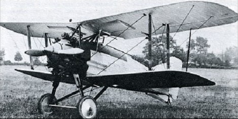
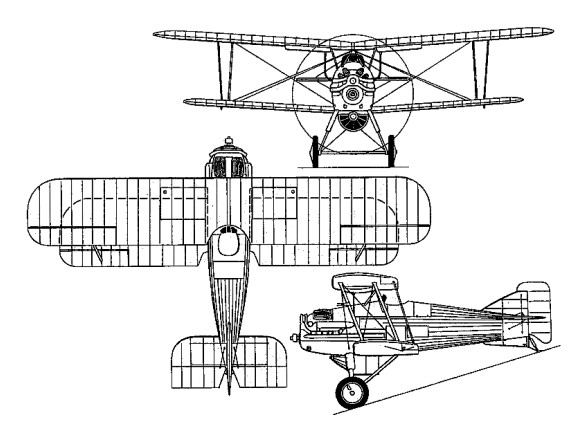
The second all-metal fighter designed by H P Folland, the Goldfinch was ordered in January 1926 as an all-metal version of the Gamecock, but, as initially completed, the prototype embodied a proportion of wood in its fuselage structure. After initial trials, the prototype was reworked, a lengthened, all-metal fuselage and revised tail unit being applied. In its new form, the prototype Goldfinch was delivered to Martlesham Heath late 1927. Powered by a supercharged 450hp Bristol Jupiter VIIF nine-cylinder radial, and having two 7.7mm Vickers Mk I synchronised machine guns, the Goldfinch offered an extremely good performance, but in competing for a production contract to Specification F.9/26 it was bested by the Bristol Bulldog.

Max take-off weight: 1468 kg / 3236 lb
Empty weight: 933 kg / 2057 lb
Wingspan: 9.14 m / 29 ft 12 in
Length: 6.78 m / 22 ft 3 in
Height: 3.20 m / 10 ft 6 in
Wing area: 25.48 sq.m / 274.26 sq ft
Max. speed: 277 km/h / 172 mph

Gloster Gannet

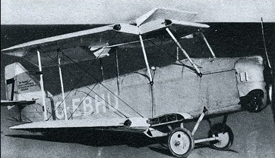
An ultralight biplane with folding wings for storing the aircraft in a garage.

Engine: 1 x Carden
Max take-off weight: 186 kg / 410 lb
Empty weight: 128 kg / 282 lb
Wingspan: 5.49 m / 18 ft 0 in
Length: 5.03 m / 16 ft 6 in
Height: 1.83 m / 6 ft 0 in
Wing area: 9.57 sq.m / 103.01 sq ft
Max. speed: 105 km/h / 65 mph
Range: 225 km / 140 miles

Gloster Gambet / Nakajima A1N1

Gloster Gambet

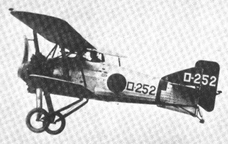
During 1926, in which year Gloucestershire Aircraft changed its name to Gloster Aircraft, the company was approached by the Japanese Nakajima, which (together with Aichi and Mitsubishi) had been asked to submit a design for a new shipboard fighter for the Imperial Japanese Navy. At this time, H P Folland was designing a shipboard fighter as a company venture. Named Gambet, the prototype was of wooden construction and powered by a 420hp Bristol Jupiter VI nine-cylinder radial, armament consisting of two 7.7rnm Vickers guns mounted in troughs in the fuselage sides. This prototype was acquired by Nakajima in July 1927, together with manufacturing rights. After modification by a team led by Takao Yoshida and installation of a 520hp Nakajima built Jupiter VI engine, the Gambet competed against prototypes of indigenous design and was ordered into production in April 1929 as the Navy Type 3 Carrier Fighter (A1N1).

Nakajima A1N1-2

Engine: 1 x Bristol Jupiter VI, 313kW
Max take-off weight: 1395 kg / 3075 lb
Empty weight: 912 kg / 2011 lb
Wingspan: 9.70 m / 31 ft 10 in
Length: 6.49 m / 21 ft 4 in
Height: 3.25 m / 10 ft 8 in
Wing area: 26.38 sq.m / 283.95 sq ft
Max. speed: 245 km/h / 152 mph
Ceiling: 7070 m / 23200 ft

Gloster Guan

Three prototype Guan single-seat high-altitude fighters were ordered at the beginning of 1925 primarily to test the application of turbo-supercharged engines to fighters.
Of mixed construction, with metal fuselage, wooden wings and fabric skinning, and provision for the standard twin synchronised 7.7mm Vickers gun armament, the first prototype was completed in June 1926, with a geared 450hp Napier Lion IV with an exhaust-driven turbo-supercharger below the propeller shaft. The second prototype followed early in 1927 with a direct drive 525hp Lion VI and turbo-supercharger mounted above the propeller shaft. Difficulties with the turbosuperchargers led to cancellation of the third prototype and abandonment of the development programme.

Take-off weight: 1725 kg / 3803 lb
Empty weight: 1348 kg / 2972 lb
Wingspan: 9.70 m / 31 ft 10 in
Length: 6.70 m / 21 ft 12 in
Height: 3.10 m / 10 ft 2 in
Wing area: 27.68 sq.m / 297.94 sq ft
Max. speed: 282 km/h / 175 mph

Gloster FS.36 / TSR.38

One prototype, first flown in April 1932. No production.

TSR.38
Engine: 1 x 690hp Rolls-Royce Goshawk VIII
Max take-off weight: 3649 kg / 8045 lb
Empty weight: 1970 kg / 4343 lb
Wingspan: 14.02 m / 45 ft 12 in
Length: 11.38 m / 37 ft 4 in
Height: 3.51 m / 11 ft 6 in
Wing area: 56.76 sq.m / 610.96 sq ft
Max. speed: 233 km/h / 145 mph
Ceiling: 6096 m / 20000 ft
Armament: 2 x 7.7mm machine-guns, 770kg of bombs
Crew: 3

Gloster TC.33

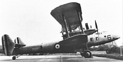
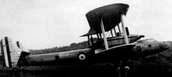
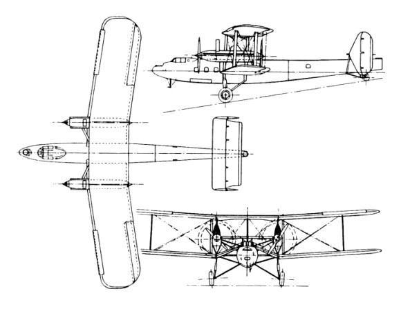
The appearance in 1930 of the four-engined troop carrier (TC) TC.33 was a complete break from their tradition and was the only four-engined aircraft that Gloster ever built. It was designed led by Henry Folland to meet Air Ministry specification C.16/28, which required the ability to carry 30 troops and their equipment for 1,200 miles (1,930 km) and was the same specification that produced the Handley Page H.P.43 and the Vickers Type 163.

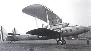
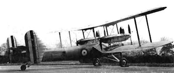
The TC.33 was a large single bay all-metal biplane with no stagger and 7° sweepback. Both wings had metal lattice spars and metal ribs with fabric covering. The lower wing was unusual in that its centre section had marked anhedral so that the main spars met at the top of the fuselage, leaving the interior unobstructed. The outer end of this centre section was strut braced to the lower fuselage. The TC.33 also had a lower wing of (slightly) greater span than the upper.

The four evaporatively cooled Rolls-Royce Kestrel engines were mounted in two nacelles, each containing a tractor-pusher pair together with their steam condenser and mounted between the wings at the end of the centre section. They were each carried by two vertical struts above the nacelle, complicated strutting below and by further strutting to the lower wing roots. The wide (22 ft 6 in (6.8 m)) split axle undercarriage had vertical legs from the front wing spar at the same point and bracing from the axles to the fuselage.

The fuselage was oval in cross section and smoothly metal skinned. The cockpit was enclosed, but there were open gunners’ positions at nose and tail. Like the cockpit, the long main cabin was heated and soundproofed. There was a large hatch in the floor for heavy loads with an integral hoist mounted above it, plus a smaller roof hatch through which loads could be lowered by crane. The biplane tail unit had conventional fabric covered endplate fins and rudders, but the tailplanes were sesquiplane type. The upper tailplane and elevator was strut mounted above the fuselage and the much narrower chord lower part fixed to the lower fuselage.

The prototype was completed in January 1931 and, because the hangar doors were low, the undercarriage had to be assembled in two trenches. The aircraft was winched in and out of the hangar by way of these trenches.

The TC.33 first flew on 23 February 1932. Development flying showed it had good performance but suffered from elevator and rudder flutter. The former was cured with mass balancing but the rudder flutter persisted, particularly in high speed dives until the rudders were redesigned.

It was exhibited at the 1932 RAF Hendon Display and then went on to RAF Martlesham Heath for trials. Once in the air, the TC.33 was judged a pleasant machine to fly, but it was crucially let down by its full load take off performance. Even at Martlesham it was hard to get it off the ground in a reasonable distance. The undercarriage behaviour was also criticised. Because of these concerns over take off performance at English temperatures and altitudes, the Air Ministry did not place an order, judging it would not cope with the hot and high conditions found at many RAF fields across the Empire. Thus J9832 was the only one of its kind. None of the C.16/28 contenders were awarded a production contract.

Gallery

Engines: 2 × Rolls-Royce Kestrel IIIS, 580 hp (432 kW) & 2 × Rolls-Royce Kestrel IIS, 580 hp (432 kW)
Props: 12 ft 6 in (3.8 m) diameter two bladed fixed pitch tractor & 11 ft 0 in (3.3 m) diameter two blade fixed pitch pusher
Length: 80 ft 0 in (24.38 m)
Wingspan: 95 ft 1 in (28.98 m)
Height: 25 ft 8 in (7.82 m)
Wing area: 2,493 ft2 (231.60 m2)
Empty weight: 18,399 lb (8,346 kg)
Gross weight: 28,884 lb (13,101 kg)
Maximum speed: at 13000 ft (3,960 m) 142 mph (227 km/h)
Service ceiling: 19,100 ft (5,821 m)
Rate of climb: to 10,000 ft (3,050 m) 408 ft/min (2.1 m/s)
Armament: 2 × 0.303 in (7.7 mm) Lewis gun, in front and rear positions & 3,600 lb / 1,633 kg bomb load on racks below fuselage
Crew: 4
Capacity: 30 troops

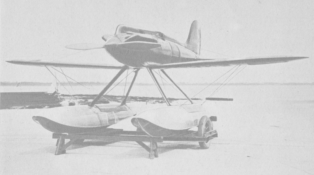
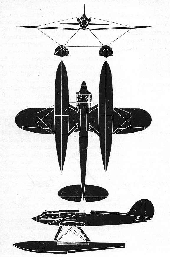
Gloster VI

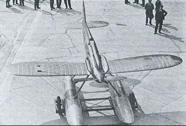
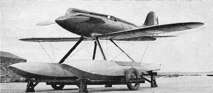
Further development of the Gloster III, the Gloster VI was the first monoplane. With spruce sheet-covering, the VI was powered with a Napier Lion VIID V-12.

Two specially built single seat racers were entered for the 1929 Schneider Trophy Contest, N249 and N250. Technical snags, petrol feed and air intake, could not be solved in time to prevent the entries from being withdrawn.

N249, flown by F/Lt G.H. Stainforth of the RAF High Speed Flight, on 10 September 1929, broke the absolute speed record averaging 336.3 mph over Calshot.

Engine: 1 x Napier Lion VIID, 984kW
Max take-off weight: 1669 kg / 3680 lb
Empty weight: 1036 kg / 2284 lb
Wingspan: 7.92 m / 25 ft 12 in
Length: 8.23 m / 27 ft 0 in
Height: 3.29 m / 10 ft 10 in
Wing area: 9.85 sq.m / 106.02 sq ft
Max. speed: 565 km/h / 351 mph