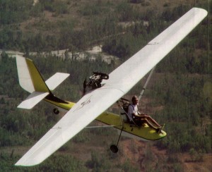
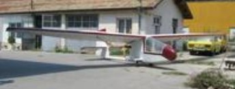
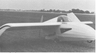
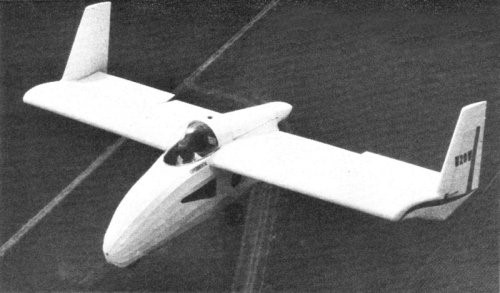
Built by Bob Bailey, circa 1991, the Connie utilises a single Cosmos trike float and qualifies as a Pt.103 ultralight. The float is the primary structural unit. Baily fitted a modified version of his Tempest ultralight sailplane wing and a Rotax 447. The main undercarriage retracts with a simple lever. On the prototype, the tailwheel retracts but this may change in a production version. The Connie may be produced with Baliey’s partner, Bill Moyes.
Prototype Engine: Rotax 447, 40 hp Wingspan: 35.1 ft. Length: 18 ft. Wing area: 118 sq.ft. Empty wt: 328 lbs. Gross wt: 570 lbs. Vne: 90 mph. Cruise: 65 mph. Stall: 35 mph. Fuel cap: 5 USG. ROC: 900 fpm. TO dist: 200 ft. Ldg dist: 300 ft.
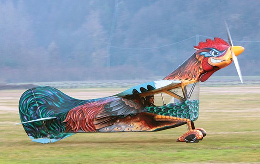
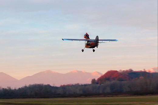
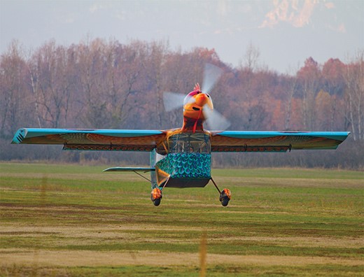
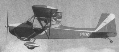
At Nervesa della Battaglia, near Treviso in northeastern Italy, aircraft designer and homebuilt aircraft enthusiast Ottone Baggio conceived the idea of building a flying machine modelled on the world’s best known flightless bird: the rooster.
The engine nacelle (the rooster’s head) would be mounted well ahead and above the wing leading edge. The design does not utilize fuselage and wing components from any other kit aircraft, and is 100% original. The wings are of a conventional, lightweight wood structure with a forward box spar that runs through the roof of the cockpit, plus trailing edge spar; there are no wingstruts, and the wings have a 1 degree dihedral. They are covered in extremely thin-gauge aluminum with a total span of 29 feet, and, unusually, the “bird” has 66%-span flaperons, but these are on the inboard sections of the wings. The wingtips are square and flattish, slightly angled inward with wingtip strobes, and the ailerons are cable operated.
Ottone Baggio with the small-scale model
The Rooster took about three years to conceive, design and build. Ottone started with model airplanes, first a “chuck” (hand-launched) glider and then a radio-controlled version. Proving that in small scale such a design would fly, he developed a prototype that would be partially like a conventional, three-axis-controlled small airplane, but would have the world’s most exotic color scheme—plus the head of a rooster.
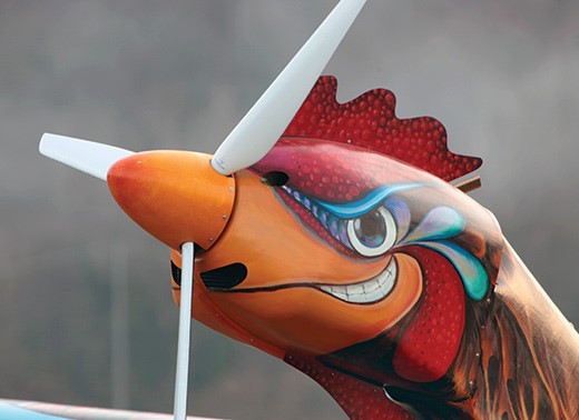
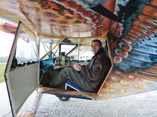
The fuselage is steel tube with gussets covered by fabric, though areas of the forward fuselage are covered in thin-gauge aluminium. The rooster’s head, which is the engine compartment, is a molded composite cowling around a tubular-steel engine bearer. The cockpit resembles that of a 1930s airship gondola with a rounded, acrylic screen and a basic panel. The rudder is linked to the tailwheel, and there are caliper brakes on the mainwheels operated from a hand-actuated brake lever on the panel. Because of the engine’s high thrust line, Baggio has designed a huge tail and rudder relative to the meager 19-foot total length of the rooster, and he even fitted a dorsal “rudder” in which the steerable tailwheel is shrouded.
It has an empty weight of 500 pounds and is powered by a 100-horsepower Rotax 912 engine. The paint job took many months of detailed work with an amazing palette of colors.
The Rooster, registered in the Italian ultralight sequence as I-9923, was actually completed earlier but suffered some fast-taxi mishaps. In December 2011, the test pilot, fellow homebuilder Daniele Beltrome carried out many fast taxi trials and a few tentative hops. “The Rooster is a difficult aircraft to fly,” he reported (no kidding!) and suggested a few adjustments to its elevators and control-wire cable tensions. The first proper flight, lasting about 10 minutes, had the Rooster leaving the airfield, completing a slow 180 turn and then returning to the airfield.
Daniele Beltrome carried out much of the initial flight testing.
Unfortunately, Beltrome further reported, “The Rooster is unstable in roll and has a tendency to go into the first stages of a spin when you start to turn, if it isn’t noticed and checked.” He put in one stage of the flaperons to try to solve this problem. This is why the first flight turn was a very gentle affair with little more than 5 of bank and often less, with a very obvious and “twitchy” pitch.
The Rooster is its control system works in reverse to a normal three-axis-control aircraft. The control column comes down from the roof of the cockpit, and the control inputs are exactly the opposite to what one learns in normal piloting skills, so you pull back on the stick to go down and vice versa. This is the reason for some of the accidents during early taxi tests. It is apparently more like flying a delta-wing hang glider.
More test flying was planned and the builder may extend the flaperons to full span to help improve roll control. But like the bird of its inspiration, the Rooster is unlikely to fly that much and achieve widespread acceptance among homebuilders and pilots. It is more the product of a dream becoming reality. However, as an aviation spectacle, the sight of the Rooster flying over the Nervesa Valley has gotten everyone talking aviation and flight, though it may also have stirred considerable unrest and disruption to egg production in local hen houses.
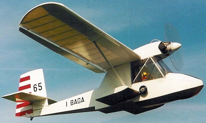
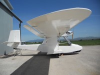
The Bagalini Baganfibio (from “Bagalini” and “Amphibian”) is an Italian homebuilt flying boat that was designed by Marino Bagalini. The two-seat tandem amphibious aircraft was supplied in the form of plans for amateur construction.
The Baganfibio features a strut-braced high-wing, a two-seats-in-tandem enclosed cockpit, retractable conventional landing gear and a single engine in tractor configuration mounted above the wing.
The aircraft is of all-wooden construction, with its wings covered in doped aircraft fabric. Its 10.7 m (35.1 ft) span wing employs an RSG 36 airfoil and has Junkers ailerons. The aircraft does not use tip floats, but instead relies on sponsons for balance in the water. The acceptable power range is 40 to 50 hp (30 to 37 kW).
Full fuel is 26 litres (5.7 imp gal; 6.9 US gal) and the payload is 151 kg (333 lb).
The manufacturer estimates the construction time from the supplied kit as 700 hours.
Plans were available in 1998.
Engine: Rotax 503, 50 hp / 37 kW Wingspan: 35 ft 0 in / 10.67 m Wing area: 167 sq. ft / 15.5 sq.m Airfoil: RSG 36 Length: 22 ft 0 in / 6.71 m Empty weight: 385 lb / 175 kg MTOW: 759 lb / 344 kg Fuel capacity: 26 litres (5.7 imp gal; 6.9 US gal) Wing loading: 22 kg/sq.m / 4.5 lb/sq ft ROC 600 fpm / 3.0 m/s Cruise: 43 mph / 69 km/h / 37 kn Max speed: 62 mph / 100 km/h / 54 kn Range: 130 mi / 210 km / 110 nmi Stall: 28 mi / 45 km/h / 24 kn Seats: 2
A small ultralight motorglider. This motorglider is available as plans only. It consists of wood and metal construction. The wings are tapered. The landing gear is fixed. Estimated building time is 700 hours. Plans price was $250. 2009 Price: 6000 EURO
The Bagimer I (also referred to as Alouette) was a two-seat homebuilt aircraft developed by Badez, Giraud and Mercier and was basically a Piper J-3/L-4H with modifications to the landing gear, wings and tail surfaces and a 75 hp Minié 4.DC.32 engine replacing the original 65 hp Continental A65. The first aircraft was built by the developers and registered F-WFAR (c/n 01) it first flew in September 1949, being reregistered F-PFAR after it received its CofA.
F-PFOK with club member Guy Thion in the cockpit
The Bagimer II was the same aircraft after it had been re-engined with the original 65 hp Continental A65. A second very similar aircraft was then constructed by members of the Aéro-club de Pithiviers, initially registered F-WFOK, later F-PFOK. Reportedly a third example, a Bagimer II, was also built in France.
Keith Bennett of Devonport, Tasmania, Australia, asked Owen Badcock about designing him a plane. Owen Badcock proceeded to draw up some plans and then built a one-quarter scale radio¬controlled model complete with folding wings. This performed completely as planned with no need for modifications. Keith started building in June 1992. All stress-bearing metal parts are chrome molydenum steel tube which after welding (T.I.G.) has been sand blasted, oil filled, primed and then painted with two-pack white. The wing ribs are Epi glued Canadian Spruce with 6m l2ply noses and tails. All moving parts are nylon bushed. An early problem with tail-wheel shimmy was solved by Keith who turned up a wheel from solid aluminium to fit a standard ball-bearing. A solid rubber tyre was vertical stabilizer and the leading edges of the wings snug up to rubber blocks on the roof and sides of the trailer as the plane settles ‘home’ upon loading. Starting of the 503 DCDI engine is facilitated by use of a G.A. type fuel primer. The wheel brakes are operated by twin levers conveniently situated forward of the throttle lever on the left side of the cockpit. This makes for very easy taxing. For parking a spring loaded lever can be rotated to hold both levers on. This unlocks automatically when the brake levers are activated. Wing folding is affected by first half withdrawing a pin on the leading-edge spar at the root of each wing. This unlocks a safety-pin which is moved ‘on’ by the last part of the pins travel when it presses down on a nylon wedge on the forward end of a rod. The aft end of the rod carries the safety pin which prevents the spring loaded flaperon disengaging mechanism separating in flight in the event of spring failure. The flaperon as are then disengaged for wing folding and held up by a small piece of shock-cord which retracts into the wing when not in use. The leading edge spar pin can then be lifted right out and the wings swing back and locked on to the tail. The whole operation takes two minutes.
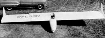
The Flying Plank was developed in 1954 by Al Backstrom, assisted by Phil Easley and Jack Powell. The prototype EPB-1 was used for drag reduction tests at the Mississippi State College, using a modified Abrial reflex airfoil.
Plans for the -1A development were sold and a number built, most with twin wingtip rudders, but some were completed with a central fin and rudder at the end of a lengthened fuselage (EPB1-C) to improve performance and control. Span have varied up to 9.30 m / 30.5 ft. A self-launching model was developed later.
Motorised
Except for the fiberglass nose cap for the fuselage, standard wood structure was used throughout, and construction time for an experience woodworker was in the neighborhood of 600 hours. More than 150 sets of plans were sold.
Central fin
Construction of the powered Plank was begun in 1972, most of the work being done by Van White, a director of the EAA (Experimental Aircraft Association). It was intended originally to fit a Sachs Wanzel or OMC snowmobile Wankel engine, but as neither became available, a fan-cooled single-ignition Kiekhaefer Aeromarine 440 was installed, driving a two-bladed pusher propeller via belts.
WPB-1 Powered Plank
The original tandem-wheel/outrigger undercarriage was replaced by a more robust tricycle unit in 1976.
An improved version, the “Super Plank”, was under development in 1973. At least two of them were built, including N20WB, by Larry Linville and Dennis Harmon. Backstrom also built a motor glider light aircraft called WPB-1 Powered Plank in early 1970s.
The Backstrom WPB-1 is on display at the Airpower Museum in Blakesburg, IA. And the Vintage Sailplane Association has plans.
The Bacon Super T-6 was a North American AT-6F Texan that was modified during the mid-1950s by the Erle L. Bacon Corporation in an attempt to interest foreign air forces in an upgrade for their T-6 fleets.
Produced in 1944 and operated by the United States Army Air Forces alongside its brethren, following the end of World War II AT-6F Texan 44-82028 was sold on the civilian market, operating in Iceland for a time before being acquired by Bacon for conversion.
Described as appearing “like an illicit hangar affair between a T-33 and a T-6”, the conversion consisted of adding the tip tanks ex-Cessna 310, canopy, and tricycle landing gear from a Lockheed T-33 Shooting Star; streamlining of the cowl and wings including jet stack exhaust, augmenter cooling, and a 4-foot (1.2 m) reduction in wingspan compared to the standard T-6; in addition, the cockpit was upgraded with a revised instrument panel and modernized avionics, and the aircraft’s brakes were upgraded.
LAX March 1957
Bacon hoped to sell the conversion to foreign air forces, many of which operated large fleets of T-6 aircraft; after taxi trials at the end of 1956, it first flew in April 1957, and flight testing was considered generally successful. No interest from its intended customers materialized and the aircraft was sold on the civilian market; it eventually received a paint scheme, believed to have been intended for a role in a movie, resembling that of a Russian fighter aircraft.
It was stored at Whiteman Air Park in California, and allowed to deteriorate in the elements, with its registration being cancelled in 2013.
Powerplant: 1 × Pratt & Whitney R-1340-AN-1 Wasp, 600 hp (450 kW) Propeller: 2-bladed variable-pitch Wingspan: 38 ft 6 in (11.73 m) Length: 29 ft 6 in (8.99 m) Height: 11 ft 8.5 in (3.569 m) Fuel capacity: 100 US gal (83 imp gal; 379 L) in two tip tanks Maximum speed: 225 mph (362 km/h, 196 kn) Cruise speed: 215 mph (346 km/h, 187 kn) at 64% power Rate of climb: 1,750 ft/min (8.9 m/s) at sea level Crew: 2 Armament: .30-inch (7.6 mm) machine guns, underwing bomb racks or rocket launchers optional
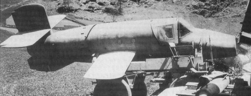
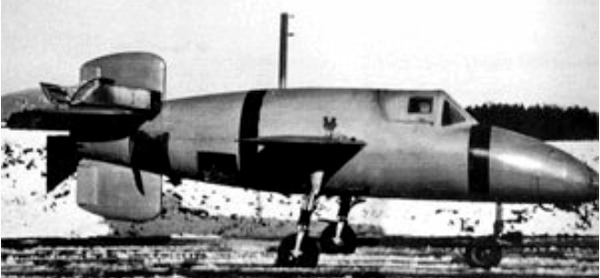
In August, 1944, that the idea of “Natter” (German for Viper) was conceived and four designers, Heinkel, Junkers, Messerschmitt and Bachem, were directed to submit plans. Diplomeur Ingenieur Erich Bachem who made his first appearance with his submission of the BP(Bachem Projekt)20 Natter (Adder). The BP-20 was envisioned as a small lightweight expendable interceptor, capable of destroying any enemy bomber using the least possible weapon expenditure. Dr. Bachem’s design was chosen and in November of that year Natter BP-20 was flown for the first time. Smaller than the Me-163 (span, 13 feet; length, 20 feet, 6 inches) and simpler to build (wooden airframe required only 600 man hours) it looks more like a mock-up than a full-fledged fighter. Because of the short take-off area required it was well suited to close defense of vital targets and pilots required very little training. Launched from a nearly vertical ramp, powered by a Walter rocket unit similar to that used in the Me-163, the initial rate of climb was calculated at 37,000 feet per minute, its top speed at more than 600 miles per hour. A controlled missile until within a mile of its target, the pilot then takes over, jettisons the nose cone exposing 24 Fohn 7.3 caliber rockets which are fired in one salvo. Protected by exceptionally heavy cockpit armor and presenting a small head-on target, the pilot is virtually invulnerable to enemy fire. His principal danger is in take-off and descent. Going into a dive after two minutes or less in the air he bails out and a section of the fuselage containing the rocket unit likewise descends by parachute. It was the first vertical-takeoff fighter ever built and certainly the first where the pilot was expected to bail out on every mission.
That project had its origin in a proposal in 1939 by rocket engineer Dr. Werner von Braun. This proposal was rejected as unworkable by the Reichluftfahrtministerium (RLM-German Air Ministry) but found an enthusiastic supporter in Bachem who tried, and failed, to generate interest in several different proposals for a rocket interceptor along the lines suggested by von Braun. The airframe was comparatively crude, largely of wood construction and was to be built without the use of gluing presses or complex jigs. Most parts could be made in small woodworking shops through Germany, without interfering with the existing needs of the aircraft industry. According to Bachem, only 600 man-hours would be required for the production of one airframe, excluding the rocket motor, which was relatively simple to manufacture when compared to a sophisticated turbojet. This motor was the same basic engine used in the Me-163 Komet interceptor, a Walter 109-509A-1 that used the reaction between two chemicals, T-Stoff (a highly caustic solution of concentrated hydrogen peroxide and a stabilizer) and C-Stoff (a mixture of hydrazine hydrate, methanol alcohol, and water) to provide 3,740 lb (1,700 kg) of thrust. Extra power for lift-off was generated by four 1,102 lb thrust solid-fuel rocket boosters bolted to the rear fuselage giving a combined thrust of 4,800 kgf (47 kN or 10,600 lbf) for 10 seconds.
The short, untapered, stubby wings had no ailerons, lateral control being exercised by differential use of the elevators mounted on a cross-shaped tail augmented by guidel vanes positioned in the exhaust plume of the main rocket. The cockpit was armored and armament consisted of 24 unguided Henschel Hs 217 Föhn 73 mm rockets mounted in tubes in the nose of the aircraft and covered by a nose cone. The cockpit was equipped with only basic instruments, the instrument panel actually serving as the pilot’s frontal armour. The pilot was protected by armour on each side of the seat, and a rear armoured bulkhead at his back separated the cockpit from the fuel tanks, which contained 6gal of a hydrogen peroxide and oxyquinoline stabiliser solution and 41.8gal of 30 per cent hydrazine hydrate solution in methanol. In operation, the Natter would be launched from a 79 ft (24 meter) tower. Guide rails would stabilize the wingtips and lower tailfin until the tower was cleared. (Towards the end of the war, as steel became scarce, the tower was replaced with a simple 29 ft [9 meter] wooden pole with a pair of shortened launch rails bolted to it. There was the need for a solid concrete foundation into which the gantry could be secured, though the wood pole version could be quickly dismantled and removed from a mounting set into such a base.) Controls would be locked during launch. About 10 seconds after launch, the solid-fuel boosters would burn out and be detached by explosive bolts and the controls would become operational. The aircraft’s autopilot would be controlled from the ground by radio; the pilot could assume manual control at any time. The Natter would accelerate upward with a proposed climb rate of 37, 400 ft (11,563 meters) per minute until it reached the altitude of the Allied bomber formations which could range from 20,000 ft to 30,000 ft (6,250 meters to 9,375 meters). The pilot would then take control of the Natter, steer it in close, jettison the nose cone, and fire all 24 of the rockets simultaneously at the bomber. The rocket fuel would be exhausted by now and the pilot was to glide downward to about 4,500 ft(1,400 meters). He would then release his seat harness and fire a ring of explosive bolts to blow off the entire nose section. A parachute would simultaneously deploy from the rear fuselage and the sudden deceleration literally throw the pilot from his seat. The pilot would activate his own parachute after waiting a safe interval to clear the bits of falling Natter. Ground crews recovered the Walter motor to use again but the airframe was now scrap. It was also envisioned that the Natter could be used on the remaining surface fleet with an air defense capability previously denied to ships. Bachem now pulled strings to get his proposal accepted. The strings that he pulled belonged to Reichsführer Heinrich Himmler, head of the Shutzstaffel (SS-Protective Staff). Himmler saw the possibility of establishing a fleet of aircraft beyond the control of the Luftwaffe and the RLM and signed an order for 150 of Bachem’s machines using SS funds. Alarmed, the RLM now approved Bachem’s design and placed their own order for 50 of the aircraft under the designation Ba-349 Natter (Adder). With orders from both the Luftwaffe and the SS Führungshauptamt (Planning Office), Bachem set up a factory to design and build his dream at Waldsee in the Schwarzwald (Black Forest) about 25 miles (40 km) from the Bodensee (Lake Constance). Wind-tunnel models which were built early in the program were shipped off for testing and the only results returned to the Bachem designers were that it would be satisfactory up to speeds of about 685 mph (1,102 km/h). An initial series of 50 Natters was built within three months of the launching of the project, and unpowered gliding trials began in November 1944. The first successful pilotless launch was accomplished on December 22, 1944, with a dummy in the cockpit. A Heinkel He-111 bomber carried one to 18,000 ft (549 meters) and released it. The pilot found the aircraft easy to control. At 3,200 ft (1000 meters), he fired the explosive bolts and the escape sequence worked as designed. A powered vertical launch failed on December 18 because of faulty ground equipment design. On December 22, the aircraft made its first successful launch with the solid fuel boosters only because the Walter motor was not ready. Ten more successful launches followed during the next several months. Early in 1945, the Walter engine arrived and the Natter launched successfully with a complete propulsion system on February 25, 1945, carrying a dummy pilot. The launch proved that the complete flight profile was workable. All went according to plan, including recovery of the pilot dummy and Walter rocket motor. Although Bachem wanted to conduct more pilotless tests, he was ordered to begin full power piloted trials immediately. On February 28, 1945, a volunteer, Oberleutnant Lothar Siebert, attempted the first manned, full power Natter launch. However, the cockpit canopy detached itself at an altitude of 1,650 ft because of improper locking. Siebert was knocked unconscious as the Natter continued to climb to 4,800ft before nosing down and crashing, with fatal consequences. More pilots volunteered to fly and the Bachem team launched three flights in March. Manned flights continued, seven of them, but only 36 of the 200 Natters ordered were completed. Altogether 25 Natters actually flew, though only seven of the flights were piloted, in April 1945 ten Natters were set up at Kirchheim near Stuttgart to await a chance to intercept Allied bombers. However, Allied tanks arrived at the launching site before the bombers appeared, and the Natters were destroyed on their ramps to prevent their capture. French tanks advanced into Waldsee on April 1945 and a great number of spare parts from the Bachem factory were captured. Only a few days before the French arrived, fifteen rocket engines destined for Nattern had been thrown into Lake Waldsee to prevent their capture. The secret was not well kept however and all were later recovered. A B model Natter, with revised armament and an auxiliary cruise chamber in the engine to increase powered endurance from 2.23min to 4.36min, was in the works at the end of the war. Three Ba 349Bs were built before VE Day, but only one was test flown. Only two authentic Nattern survive. One is at the Deutsches Museum in München (Munich), restored in the colors and markings of one of the unmanned test aircraft. The Smithsonian Institution’s National Air and Space Museum in Washington DC has the other Natter which was captured by U. S. forces at the war’s end and shipped it to Freeman Field, Indiana, for analysis. The captured equipment number T2-1 was assigned to the Natter and the US Air Force transferred it to the National Air Museum (now NASM) on May 1, 1949.
Ba 349 Engine: One Walter HWK 509A rocket + 4 solid rocket boosters, 16.7 kN (10,600 lbf) Launch weight: 800 kg (1940 lb) (empty), 2,232 kg (4,920 lb) (full load) Length: 6.02 m (19 ft 9 in) Height: 7 ft 4.5 in Wing span: 3.60 m (11 ft 10 in) Wing area: 51.6 sq.ft Speed: 1,000 km/h (620 mph) Range: 6 min of flight Flying altitude: 14,000 m (46,000 ft) Warhead: 24x 73 mm Hs 217 Föhn rockets or 33x 55 mm R4M rockets
Ba 349A Powerplant: one 1700 kg (3,748 1b) thrust Walter 109 509A 2 liquid fuel rocket motor (of 70 sec power duration) and four 1200 kg (2,646 lb) thrust Schmidding 109 533 solid fuel jettisonable booster rockets (of 10 sec power duration). Max speed: 800 km/h (497 mph) at SL / 560 mph at 16,400ft Service ceiling: 14000 m (45,930 ft) Initial ROC: 11140 m (36,550 ft)/min. Radius of action: 40 km (24.8 miles). Launch Weight: 2200 kg (4,850 lb). Wing span: 3.60 m (11 ft 9.75 in) Length: 6.10 m (20 ft 0 in) Wing area: 2.75 sq.m (29.6 sq.ft) Armament: 24 Fohn 7.3 cm (2.87 in) unguided rocket projectiles in nose.
Ba 349B-1 Engine: One 4,409 lb (2,000 kg) st Walter HWK 509C 1 bi fuel rocket motor, plus (for take off) four 1,102 lb(500kg) or two 2 205 lb (1,000 kg) Solid fuel rockets. Wing span: 13 ft 1.5 in (4.00m). Length: 19 ft 9in (6.02 m). Wing area: 50.59 sq.ft (4.70sq.m) Gross weight: 4,920 lb (2,232 kg). Max endurance: approx 4 min. Crew: 1 Initial ROC: over 37,000 ft (11,280 m)/min. Max speed: 620 mph (1000 kph) at 16,400 ft (5,000 m).