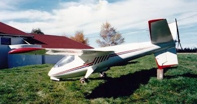
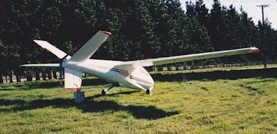
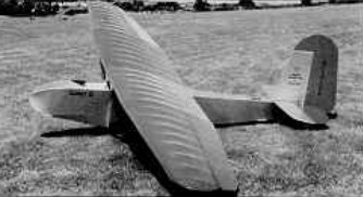
Bill Barber of Dacre in Southland, New Zealand, started off with the Snark HA 1 which was a single seater. Barber Snark HA 1 ZK-FOU (c/n MAANZ 409) was first registered to Bill Barber on 11/8/87. It was built of Kevlar foam sandwich construction with carbon fibre spars and full flaperons. It had a Rotax 503 engine driving a 3 bladed propellor through an 8 foot long driveshaft.
Barber flew the Snark HA 1 twice, for two short hops, and on reflection thinks it was a good aircraft. However, development problems caused him to go on to design and build his two seater Snarks.
This view shows the unusual tail configuration. ZK-FOU was withdrawn and cancelled on 26/7/95. It is currently stored on a trailer at Mandeville.
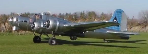
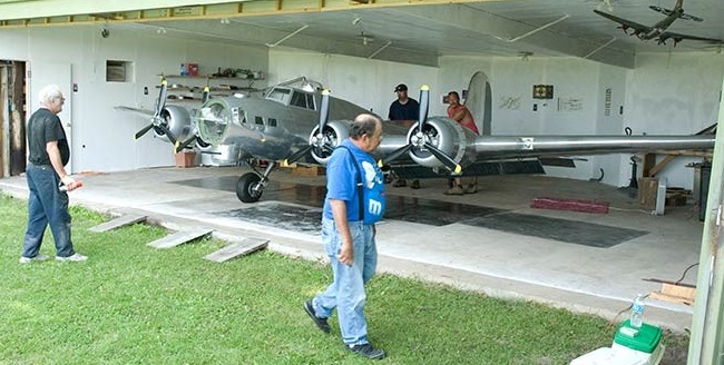
Bally’s Bomber is a ⅓ Scale B-17G aircraft built using 1/9 scale RC model aircraft plans, and carries a single pilot. It is powered by four Hirth 3002 4-cylinder 2-stroke engines, spans 34′ 7″ and weighs an estimated 1,800 lbs.
The unique aircraft received airworthiness certification in September 2016 following initial engine and taxi tests. The first flight was intended to be a high speed taxi test, but the machine was said to “just kind of [take] off”.
On 14 November 2016 Jack Bally`s 1/3 scale B-17 replica performed its maiden flight, departing from its home field in Illinois for a short flight to a local airport, where it was to undergo continued flight tests.
Power Plant: 4 x Hirth 3002, 60 hp Wing Span: 34 ft. 7 in. Length: 25 ft. Tail Height: 6 ft. 10 in. Fuel Capacity: 42 USgal. Empty Weight: 1800 lbs. (Est.) Cruising Speed: 110 kts. (Est.) Crew: 1 Number Built: 1
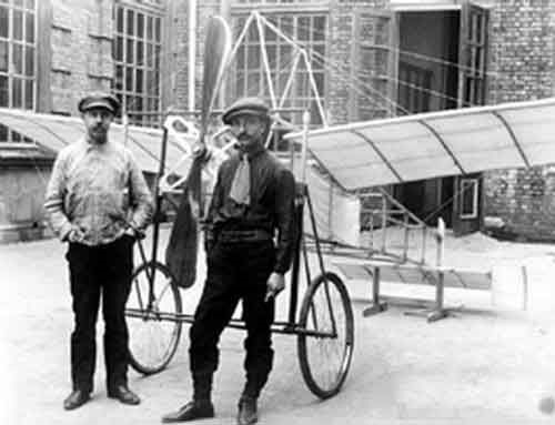
Built by a group of students at the polytechnic school of Baku (today Azerbaijan) in 1910. Based on Blériot’s famous monoplane, albeit a little smaller.
Increasing the wing area produces a noticeable increase in lift caused by the laws of aerodynamics. With more lift the crash speed becomes lower and therefore the aircraft can stay in the air with less “effort”. The increase in speed demands a decrease in the surface and therefore an increase in the load on each point of the wing.
Air combat aircraft seek to increase performance at the cost of greater driving power and a decrease in wing area, but even this type of aircraft is forced to carry out operations at low speeds such as approach and landing.
Aeronautical development has brought different solutions to this problem, among which the use of flaps and variable geometry in aviation stand out. In the 1930s in the USSR the aeronautical engineer Georgi Ivanovich Bakshayev proposed an interesting method to achieve the same effect. The practical implementation of his theory came to light in the form of the RK aircraft “Razdvizhnoe Krylo”, which was successfully tested in 1937.
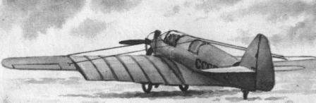
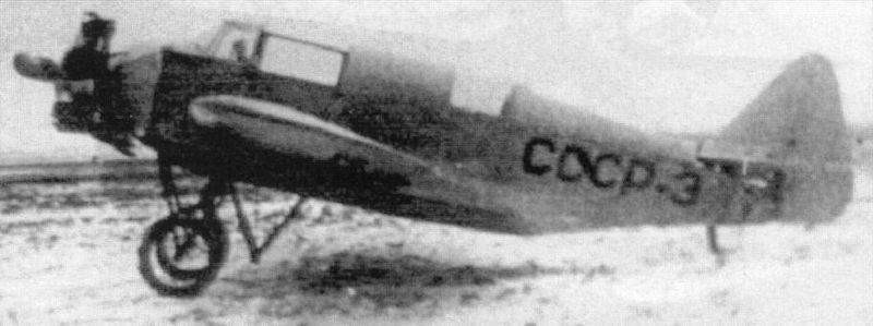
The RK owes its name to the strange telescopic wing configuration (Razdvizhnoe Krylo – sliding wing), being also known as LIG-7 to indicate its development within the Leningrad Civil Aviation Fleet Institute. The main objective of this model was to obtain the smallest wing area for horizontal flight operations and its increase during takeoff and landing.
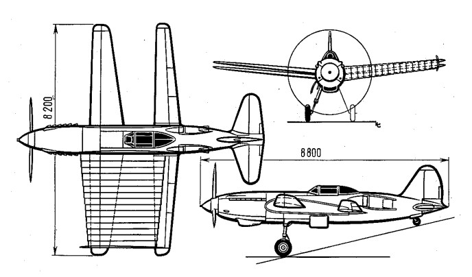
Designed as a conventional type two-seater monoplane with a 100 hp M-11 engine, this airplane was used as a test bed for a variable surface experimental wing. The RK was conceived as a low-wing monoplane aircraft braced by cables. This wing, made of wood, was characterized by having a wingspan of 11.3 meters, a constant chord (1.5 m) and a great aspect ratio, which allowed for improved performance during flight at cruising speed. With an M6 wing profile, the internal structure was designed on the basis of two wooden stringers. The covering was fabric. The wing featured bracing cables running from the top of the cabin and from a special cabin structure located in the ventral region.
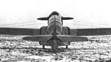
Rear view of the RK in configuration with the segments collected.
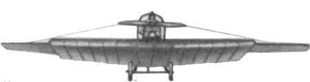
During takeoffs and landings, lift was increased by the extension of 6 telescopic sections, which increased the surface area of the wing to occupy two thirds of the wingspan, giving a total area of 23.85 sq.m. Each section, constructed of plywood, was 500mm wide with a 40mm overlap. The profile in this case was the TsAGI-846. The sections featured lightweight support ribs in the inner section constructed of pine and 2mm thick plywood overlay. The extension or retraction system was achieved by means of a steel cable that was operated manually from the cockpit. During the flight all sections were hidden inside the fuselage. The outer wing section with ailerons (one third of the wingspan) was not covered by the sections.
Front view of the RK in configuration with the segments extended.
The RK was ready for testing in 1937. The entire system worked well, with a retraction time of 20 to 30 seconds and extraction time of between 30 and 40 seconds. Retraction and extension were found to be easier in the air than on the ground.
The designers took overload and symmetry into account in the extraction / retraction process and this allowed for no negative effects during in-flight system testing. The center of gravity was established at 26% of the length.
The effect achieved during takeoff and landings was remarkable and the technology proved applicable. The speed did not increase considerably with the collected system, since it maintained a 20% resistance caused by the installation of the structure. Despite this, it was clear that the positive impact of this technology would be extremely useful on larger and faster aircraft, where resistance to wing advancement increases.
This advantage was of little use in civil aircraft. For this reason in 1938 Bakshayev proposed to develop an airplane to set speed records with this Klimov M-105 alar and power plant principle , but the project received no support, however an order was received to build a single-seater fighter using the Alar technology of the RK that was due to be ready for testing in 1940 and was known as Bakshayev RK-I (RK-800).
Engine: 1 x 100 hp M-11 piston engine Wingspan: 11.3m Length: 7.34 m Wingspan of extended sections: 6.27 m Wing area with retracted sections: 16.56 m² Wing area with extended sections: 23.85 m² Empty weight: 667kg Loaded weight: 897kg Wing load with sections retracted: 54.2 kg / m² Wing loading with extended sections: 37.6 kg / m² Power Load: 9.0kg / hp Fuel and oil weight: 70 kg Speed at sea level with sections retracted: 150 km / h Speed at sea level with extended sections: 144 km / h Landing speed with sections retracted: 100km / h Landing speed with extended sections: 75km / h Landing run with sections retracted: 210 m in 12 seconds Landing run with sections extended: 110m in 9 seconds Take-off run with sections retracted: 250m in 14 seconds Take-off run with sections extended: 135m in 9 seconds Range with sections retracted: 400 km Range with extended sections: 370 km Autonomy: 3.0 h Ceiling: 2900m Ascent time to 1000m: 7.5 minutes Ascent time to 2000m: 19.5 minutes Accommodation: 2
The Cadet was designed in 1929 by Dr. Frank R. Gross, a former member of the Akaflieg Darmstadt, as an improvement offering some soaring capability over the existing primary gliders. Built of steel tube fuselage, wood dual spar/ dual strut wing, wire braced wood tail, all fabric covered. Jack O’Meara, a demonstration pilot for Baker McMillen, flew a Cadet off South Mountain at Elmira, NY for 1 hour and 38 minutes in the summer of 1930 starting what was to become Harris Hill as the home of American gliding. One Cadet even flew on twin floats, and three of them (along with a Sky Gost, another Gross design) were towed at on time by a Goodyear Blimp over Akron, OH. One remained airworthy in the 1990s.
Circa 1964 mechanic Marion Baker utilised free flight models in the development of his MB-I Delta Kitten homebuilt experimental aircraft.
A tailless, Lippisch-like delta of all-metal construction and tricycle gear, the MB-1 was winner of EAA Design Trophy in 1961. The one built was registered N57A and cost $2,000 to build.
Those who flew the plane found it gentle and orthodox in response.
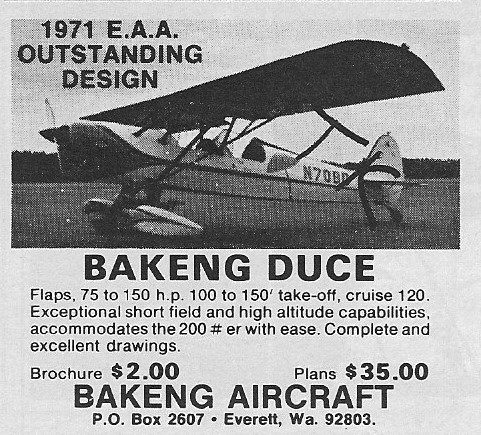
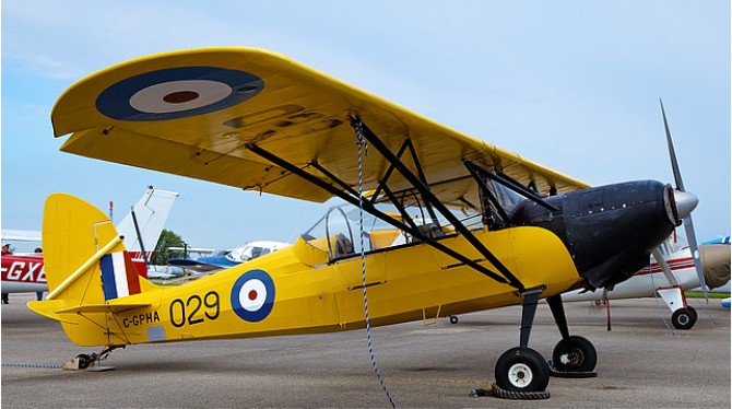
The Bakeng Deuce is a two-place parasol design utilizing a steel tube fuselage. The structure is faired with plywood and aluminum formers which support spruce stingers. Wings are of basic wooden construction with solid spruce spars.
First flown on 2 April 1970, this homebuilt received the ‘Outstanding New Design” and “Design improvement’ awards from the EAA in 1971. The V-strut braced wing utilizes both metal and spruce construction and is covered with fabric. The fuselage is also fabric-covered but is built from steel tubes. The landing gear is the conventional tailwheel type, and the two seats are arranged in tandem fashion. Bakeng has also designed a biplane version of the Duce, called the Double Duce. Both horizontally opposed and radial engines can be used, from 85-150 hp. Baking Deuce Airplane Factory purchased the rights to the Bakeng Duce in March of 1999. The name was changed to “Deuce” to separate those aircraft built before and after. The new Deuce incorporates the design of the old Duce with improvements based on analyzing the aircraft and listening to builders who have built and flown them for the past thirty years.
Dec 1973
Design Improvements are changes only to enhance integrity, reliability, ease of construction or function. These changes include: Beef up fuselage behind the landing gear legs. Complete redesign and relocation of the rudder pedals, cables and toe brakes. Complete redesign of the elevator control (pushrods instead of pulleys). Completely new lift strut attachments (individual, like old Pipers). Different tail mount structure New attachments for turtle deck Entirely new rudder design and mount (now removable). New method of attaching cross wire bracing in front of front cockpit. Removal of all elevator pulleys and cables. Larger fuel tanks Comfortable, factory-built bucket seats CAD drawings of the original plans have been completed.
It is unknown when Baird first developed an interest in aviation, but he certainly corresponded with early pioneers such as Louis Bleriot and S. F. Cody about the finer points of aircraft design. A visit to the Blackpool Aviation Week in October 1909 seems to have given focus to his enthusiasm, and when he returned to Rothesay he began work on an aircraft of his own design, the Baird Monoplane. This was generally similar in layout to the aircraft in which Bleriot had made the first crossing of the English Channel on 25 July 1909, albeit with a unique control system. His aircraft also had a four-cylinder air and water-cooled engine made by Alexander Brothers in Edinburgh. The body was constructed from tubular steel and the wings were covered in silk sewn by Mrs Baird.
The completed Baird Monoplane went on display in Rothesay during the summer of 1910, and was a star attraction at the Bute Highland Games on 20 August 1910. It is unclear whether Baird himself had been one of the 250,000 people to attend the Lanark Air Show, the first to be held in Scotland, between 6 and 13 August 1910, but given his interest in aviation it would seem odd had he not been there.
Early on the morning of 17 September 1910, the Baird Monoplane was transported by cart across Bute to Ettrick Bay, on the island’s west coast. It was a fine day, and a small crowd had gathered, including a correspondent of Flight magazine. Baird started the engine, and advanced the throttle. According to the report in that week’s Flight the aircraft accelerated over the sand and took off correctly, but having cleared the ground then veered to the right, landing with a crunch that buckled one of the main wheels and slightly damaged a wing.
Having succeeded in making (albeit briefly) the first flight of an entirely Scottish aircraft, it is not known if Baird ever flew his monoplane again. What set his achievement apart was the entirely Scottish nature of the undertaking.
It is said that the engine from the Baird Monoplane was given to a museum in Glasgow in the 1950s, and the propeller was donated to the National Museum of Flight in 2010, to mark the centenary of the flight.
While it was on show over the summer of 1910, the Baird Monoplane was examined by Thomas Sopwith, who would later become an aviation pioneer in his own right and an aircraft manufacturer. With Baird’s permission, Sopwith drew on some of the novel ideas in the Baird Monoplane when he later began building his own aircraft, which went on to have a significant impact during World War One. Baird’s name was also remembered when, in 2010, the small Bute Airstrip near the southern end of the island was renamed in his honour as Baird Airstrip.