In 1957 the model 140 jigs (last used in 1953) were renovated and used for a new tricycle undercarriage trainer, the model 150, first flying in September 1957. Available from 1959 the early model 150s had aluminum tail cones that slope uninterrupted from the wings to the base of their squared tails, and were powered by an 80 hp / 75kW Continental O-200 engine, the installation of dual controls being optional. The airplane was sold in three different versions (standard, trainer, and commuter varying only in deluxe extras), the most elaborate of which, the Commuter, listed for $8,545 in 1959. Just over 2,000 square tails were built 1959 to 1963. At 1,500 pounds, the square tails grossed out 100 pounds lighter than later models. Those 150s cruised faster and farther, climbed better and flew higher than their progeny. In 1961 the main gear was shifted aft two inches, thereby solving an earlier tail heaviness on the ground. The 1964 model marked the beginnings of cosmetic refinements. The 150C introduced a ‘family seat’ for one or two children of 80 kg maximum. The 150 now offered “Omni Vision” as the CE-150D. The airplane’s tail cone was cut down and a rear window was added. The gross weight rose to 1,600 pounds, increasing the useful load by 80 pounds and the luggage compart¬ment capacity by 40 pounds to 120. Accompanying performance changes were lowered speeds, ranges and ceilings. Retaining the vertical tail surfaces of the earlier models this, the rarest of all the 150s, was built for only two years. Two years later, Cessna increased their trainer production five fold, and 150 prices decreased by 10 percent. Electric flaps were added, and the tail was swept back with the introduction of the CE-150F. Accord¬ing to some mechanics, workmanship on the new, cheaper model was sloppy, so that 1966 airplanes require more maintenance. By the next model year, the maintenance problems had been solved, and the panel was redesigned to group the primary instruments in front of the pilot. The top of the panel was squared off, thereby increasing visibility. That airplane was listed for $9,950 in 1967.
Cessna C-150H
In 1970, Cessna introduced the Model A150K Acrobat, a 150 with structural changes to allow aerobatics. It is rated at +6G to -3G, which permits most standard acrobatic maneuvers such as snap rolls, barrel and aileron rolls, Cuban eights, loops, etc. Empty weight of the Aerobat is slightly higher than the standard 150, and speed is reduced by two mph. Total production struggled to reach 1200.
Since then the changes have been largely cosmetic with new spinner, wheel fairings, dorsal fins, and engine types. Identified as models l50F to 150M, built until 1977 and the introduction of the model 152.
Cessna C-150H
The 150’s 100 hp Continental 0-200 A had an original TBO of only 600 hours, but that number had doubled by 1964 and tripled by 1969.
Production at Wichita was boosted by licence production in France, Colombia, and Argentina. All French Rheims built CE-150s had the 130hp Rolls-Rotce Continental engine fitted as standard.
D-EDVR Reims-Cessna F.150 M 1363
Production began in August 1958 and by the time it ended during 1977 a total of 23,836 had been built, this figure including 1,754 built in France by Reims Aviation under the designation Reims F-150.
CE-150 Engine: 1 x Continental O-200-A, 100 hp. Wingspan: 32 ft 8.5 in / 0.97 m Length: 23 ft 0 on / 7.01 m Wing loading: 10.2 lb/sq.ft. Pwr loading: 16 lb/hp. Gross wt: 1600 lb. Empty wt: 990 lb / 458 kg Equipped useful load: 554 lb. Fuel cap: 135/210 lb. Payload max fuel: 344 lb. Range max fuel/75% pwr: 579nm/5.5hr. Range max fuel / 55% pwr: 734 nm/ 7.7 hr. Service ceiling: 12,650 ft / 3850 m 75% cruise: 102 kt / 117 mph / 188 kph 55% cruise: 96 kt. Stall: 42-46 kt. 1.3 Vso: 55 kt. ROC: 670 fpm / 204 m.min Min field length: 1385 ft. Seats: 2.
CE-150 Commuter Engine: 1 x Continental O-200-A, 100 hp. Wingspan: 33 ft 2 in / 10.11 m Length: 23 ft 9 in / 7.24 m Wing loading: 10 lb/sq.ft. Pwr loading: 16 lb/hp. Gross wt: 1600 lb. Empty wt: 1060 lb / 480 kg Equipped useful load: 480 lb. Fuel cap: 135/210 lb. Payload max fuel: 270 lb Baggage cap” 120 lb / 54 kg Range max fuel/75% pwr: 584nm/5.5hr. Range max fuel / 55% pwr: 742 nm/ 7.7 hr. Service ceiling: 12,650 ft / 3850 m 75% cruise: 102 kt / 117 mph / 188 kph 55% cruise: 97 kt. Stall: 42-46 kt. 1.3 Vso: 55 kt. ROC: 670 fpm / 204 m.min Min field length: 1385 ft. Seats: 2
CE-A150 Aerobat Engine: 1 x Continental O-200-A, 100 hp. Seats: 2. Wing loading: 10.2 lb/sq.ft. Pwr loading: 16 lb/hp. Gross wt: 1600 lb. Empty wt: 1076 lb. Equipped useful load: 478 lb. Payload max fuel: 268 lb. Range max fuel/75% pwr: 579nm/5.5hr. Range max fuel / 55% pwr: 734 nm/ 7.7 hr. Service ceiling: 14,000 ft. 75% cruise: 105 kt. 55% cruise: 96 kt. Stall: 42-46 kt. 1.3 Vso: 55 kt. ROC: 670 fpm. Min field length: 1385 ft. Fuel cap: 135/210 lb.
CE-150D Engine: 100 hp Continental O-200-A Wingspan: 33 ft 6 in Length: 21 ft 7 in Height: 7 ft 10 in Wing area: 160 sq.ft Empty weight: 970 lb Loaded weight: 1600 lb Max speed: 125 mph at SL Cruise 75%: 122 mph at 7500 ft ROC: 670 fpm Service ceiling: 12,650 ft Max range: 565 mi at 99 mph
CE-A150L Aerobat Engine: Continental O-200A, 100 hp. Prop: McCauley 69 in. Pwr loading: 16.0 lb/hp. Wing span: 33 ft 4 in. Wing area: 156.9 sq.ft. Wing loading: 10.2 lb/sq.ft. Length: 23 ft 9 in. Height: 8 ft. 0 in. Seats: 2. Baggage cap: 120 lbs. Category: Normal / Utility / Aerobatic. Max wt (aerobatic): 1600 lbs. Empty wt: 1040 lbs. Fuel cap: (std) 26 USG, (Optional aux): 38 USG. Max cruise: 140 mph. Maneuvering speed: 118 mph. Stall: 48-55 mph. T/O dist: 735 ft, (50 ft: 1385 ft). Ldg dist: 445 ft (50 ft: 1075 ft). ROC: 670 fpm. Service ceiling: 14,000 ft. Endurance / Range: (std fuel) 6.1 hr / 580 sm, (Optional aux fuel) 9.4 hr / 900 sm. Design load: +6 / -3 G.
CE-A150M Aerobat Engine: Continental O-200-A.
Reims Cessna F.150 Commuter
Reims Cessna F.150L
Reims Cessna FRA.150L
FRA 150L Aerobat Engine: RR-Continental, 130 hp. Cruise: 100 kt.
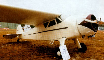
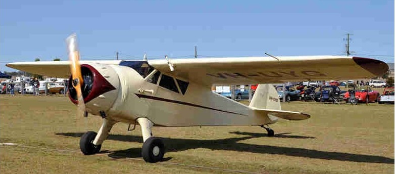
The Cessna Model 120 prototype, first flown on 28 June 1945, was a two-seat cabin monoplane with a strut-braced high-set wing. The structure was all-metal, except for fabric-covered wings, the landing gear was of fixed tailwheel type introducing cantilever spring steel main units, and the enclosed cabin provided two seats side-by-side and dual controls as standard. Powerplant a 80 hp / 63kW Continental engine, and the higher power of this unit by comparison with competing types, plus a low price tag, ensured that Cessna gained an unexpectedly large measure of sales success. New for Cessna were the all-metal fuselage and spring steel undercarriage designed by Steve Wittman of EAA fame. The wing was fabric covered and featured rounded wingtips.
The Model 120, a basic aircraft, was complemented by a ‘de luxe’ Model 140 which provided as standard manually actuated trailing-edge flaps, extra cabin windows behind the doors and a full electrical system. Cessna’s 140 was a deluxe version of the 120 model when both debuted in 1946. With a few cabin refinements, the 140 had a starter, generator, battery, and manually operated plain-hinge flaps. Both were powered by the Continental C85-12 of 85-hp, but the 140 could accept the 90-hp Continental.
CE-140
A total of 2,164 120s were produced by Cessna before this model was phased out in 1948. The side-by-side two-seat 140 continued in production with a choice of the 85-hp or 90-hp engine.
CE-140A
Introduced in 1949 as the 140A, the 90-hp version had a metal skin in place of fabric covering on the wings. It featured single wing struts in place of the earlier “Y” struts. More than 5,500 140s and 140As were built before the series was permanently discontinued in 1950.
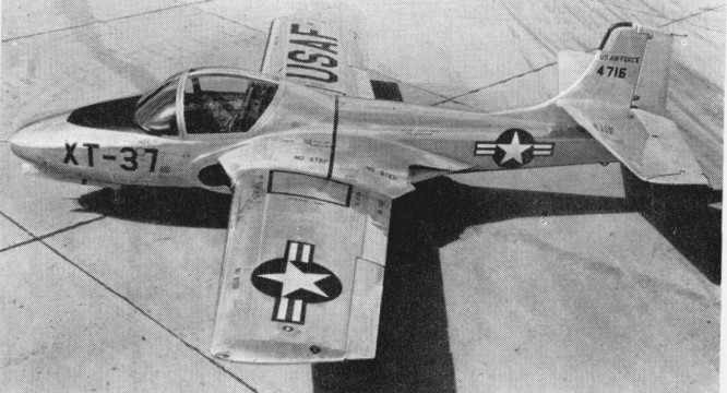
Late in 1952 the USAF formulated a requirement for a jet trainer which would economically permit student indoctrination at an early stage in the training curriculum. Specified design requirements included an empty weight of 4,000 lb (1814 kg) in order to limit both cost and complexity of the aircraft; the ability to undertake twenty take offs and landings within a two hour period; flight handling characteristics matching those of the most modern operational fighters; a 35,000 ft (10668 m) cruise ceiling with sufficient high altitude manoeuvrability to wholly orientate students, and a maximum traffic pattern speed of 113 knots (209 km/h) to assure good low speed handling characteristics. Side by side seating for the student and instructor was favoured. The Marbore II became the Continental J69 and the Cessna company designed their Model 318 around two J69s. This aircraft was a basic jet trainer. In the ensuing design contest, Cessna’s Model 318 was designated the victor early in 1953, and as XT 37s, three prototypes (54 716 to 54 718) were ordered.
The first of these flew on October 12, 1954, (piloted by Bob Hagen), powered by two Continental YJ69 T 9s (licence built Turbomeca Mabore IIs) with 920 lbf (4.1 kN) thrust each, by which time its manufacturers had been awarded a $5 million contract for eleven pre production T 37A trainers (54 2729 to 54 2739), the first of which flew on September 27, 1955. One of the XT-37 prototypes was lost in a flat spin; the pilot baled successfully. Some strengthening of the wing centre section was found to be necessary, the cockpit layout had to be revised, and field trials with the pre production machines were accompanied by minor teething troubles, among these being the fuel system of the Continental J69 turbojets licence built Turbomeca Marbore IIs, but these were soon overcome, and by the early spring of 1956, contracts had been placed for twenty (55 4302 to 55 4321) and 127 (56 3464 to 56 3590) production T 37A trainers, a contract for a further 123 machines (57 2230 to 57 2352) following shortly afterwards, and the 200th T 37A rolling off the assembly line on July 23, 1958. 534 were built under successive contracts, but were slow in entering service as a result of the need for a number of changes and modifications before they were considered acceptable for training purposes.
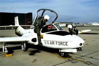
The first T-37A was completed in September 1955 and flew later that year. The T-37A was delivered to the U.S. Air Force beginning in June 1956. In the spring of 1957, the first training courses on the T 37A had begun at Waco, Texas, the first class of twenty students receiving 150 hours on the new jet trainer after forty hours on the piston engined Beech T 34A primary trainer. The second group of students at Waco had only twenty hours on the T 34A as the next stage in evolving an all jet curriculum.
In April 1961 all-through jet training was initiated, the pupil flying from the very beginning of his training on T-37 aircraft which had a speed range of 138-684km/h. No catastrophic accident rate resulted, as had been feared by many, but one point which had not been fully considered was the much higher training cost using jet aircraft. There is inevitably a varying pupil rejection rate at the end of primary training, and it was decided in 1964 to revert to light piston-engine trainers, which are much cheaper to operate, for this primary phase, so that T-37 pupils were those left after the first weeding-out.
The T 37A was powered by the 920 lb.s.t. (417 kgp) J69 T 9 turbojet, but during 1959, after the delivery of 416 aircraft of this type, production switched to the T 37B with 1,025 lb.s.t. (465 kgp) J69 T 25 turbojets, and new Onini and UHF equipment, the first of the improved trainers being accepted by the USAF on November 6, 1959. Subsequently, all T 37As passed through a modification programme to bring them up to ‘B’ standards.
For the training role, Cessna chose straight wings, twin wing root mounted engines and side by side seating. The original 417 kg (920 lb) thrust Continental J69 9 engines, built under licence from Turbomeca, were not calculated to make the American type a startling performer.
The T 37B is basically a low wing cantilever monoplane of all metal construction, and has its twin J69 T 25 turbojets mounted in the thickened wing roots, their inboard location creating a negligible change in directional control with one engine inoperative, and facilitating the demonstration of single engine procedures. A single stage, centrifugal compressor engine, the J69 T 25 has a fully automatic altitude compensating fuel control, and the two power plants draw their fuel from the main fuselage tank immediately aft of the cockpit, this being fed from six inter connecting rubber cell fuel tanks in each wing, the total usable capacity of these being 257 Imp. gal. (1 168 lt). Engine driven pumps and submerged booster pumps drive the automatic fuel transfer system, but in the event of a fuel proportioner or electrical system malfunction, fuel is automatically supplied to the engines by the gravity system.
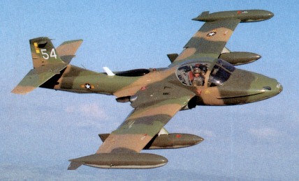
The low ‘sit’ of the T 37B on the ground eliminates the need for cockpit entrance ladders, flush steps in the fuselage 24 in (61 cm) above the ground providing easy entrance from either side of the aircraft. The cockpit itself is ideally situated, well forward of the wing, and, with the backward folding, jettisonable clam shell type canopy offers excellent visibility. The panel itself is a relatively simple and straightforward approach to current requirements. The primary instruments are duplicated for instructor and student, all instruments may be monitored, and all operating controls and switches are easily accessible from either seat. Positioned to port on the student’s side are the navigational and flight instruments, including directional and attitude indicators, altimeter, turn and bank, rate of climb and airspeed indicators, and course indicator. In front of the instructor on the starboard side but within reach of the student are the radio controls, circuit breaker, etc., and the engine instruments mounted over the central quadrant include tachometers, fuel flow and exhaust temperature indicators, fuel and oil pressure gauges, loadmeters and accelerometer. The stick grips and throttle quadrants are of fighter type. A 1,500 psi (105.5 kg/sq.cm) hydraulic system is installed. Two engine driven, constant displacement hydraulic pumps are used to drive the landing gear and doors, speed brake and thrust attenuators, nosewheel steering system, flaps and stall spoilers. The hydraulically operated brakes are independent of this system. The electrical system comprises two 200 amp. starter generators, one 24 volt, 36 amp hour battery and associated control equipment. No ancillary starting equipment is necessary, the battery being sufficient to provide engine starts for all normal training operations. Structurally, the T 37B comprises a semi monocoque fuselage, a two spar aluminium alloy wing of NACA 2418 section at the root and NACA 2412 section at the tip, and a normal cantilever monoplane type tail assembly of which the fin is integral with the fuselage, and the tailplane is mounted one third of the way up the fin. Hydraulically operated high lift slotted flaps with a total area of 15.1 sq ft (1.4 sq.m) are mounted inboard of the ailerons which have a total area of 11.3 sq. ft. (1.05 sq.m), and all movable tail surfaces have electrically operated trim tabs. Because of its low drag characteristics, an hydraulically actuated speed brake is located on the underside of the fuselage nose section, aft of the nosewheel well. This brake works in con¬junction with thrust attenuators which deflect the exhaust blast and permit higher rpm during landing approaches. When the attenuators are extended, the resultant effective thrust is reduced by more than forty per cent. Both attenuators and speed brake are controlled by the speed brake switch when the throttles are below seventy per cent rpm. The thrust attenuators automatically retract when the throttles are advanced above seventy per cent rpm. The undercarriage has two extension systems, the primary system being hydraulically actuated and the secondary system being pneumatically powered. The wheel brakes are, as previously mentioned, operated by a separate hydraulic system controlled by dual rudder and brake pedals, and the wide track of the main members (14 ft 0.5 in. 4.28 m) results in an unusually high degree of ground stability. The T 37B demonstrates good stability in all configurations and conditions of flight. Extremely effective control surfaces result in instant response, and light forces, well balanced between the three controls, make all manoeuvres easily co ordinated. Spins are mild and recovery by use of standard procedure is positive. The excellent stall characteristics are well defined with lateral control effective at all times, and good stall warning is provided for all flight configurations. Landings are accomplished equally well from either scat, and no abrupt pitch or directional trim change results when power is added for another circuit of the field. These characteristics are ideal for a training aircraft but they also result in an excellent weapons platform, and supplanting the T 37B trainer on the Wichita assembly line as the T 37C which has underwing attachment points for offensive stores or drop tanks and is intended primarily for supply to the smaller nations militarily aligned with the USA. With a gun sight mounted in the cockpit, underwing racks can carry bombs or rocket, gun or photographic pods for internal security duties, and the T 37C served with such coun¬tries as Portugal (30) and Vietnam. Mission range may be increased to more than 1,100 nautical miles (2 040 km) by the addition of wingtip tanks which, each containing 54 Imp gal. (246 lt), increase the total fuel capacity to 366 Imp gal. (1664 lt). Fuel is transferred from the tip tanks to the wing tanks by inline booster pumps, utilizing the existing internal fuel system, and provision is made for jettisoning. When production ended in 1977 a total of 1,268 T-37s had been built for the USAF and for export. During 1962 two Cessna T-37B trainers were evaluated by the USAF’s Special Air Warfare Center to consider their suitability for deployment in the counter-insurgency (COIN) role. These were first tested with their original powerplant of two 465kg thrust Continental J69-T-25 turbojets, at a take-off weight of 3946kg, almost 33% above the normal maximum take-off weight. Subsequently the airframes were modified to accept two 1089kg thrust General Electric J85-GE-5 turbojets. This increase in power made it possible for the aircraft, then designated YAT-37D, to be flown at steadily increasing take-off weights until a safe upper limit of 6350kg was reached. After successful trials Cessna were requested to convert 39 T-37B trainers from the production line to a light-strike configuration, a contract being awarded in 1966. Designated A 37A, they were delivered, only being withdrawn from service ten years later in 1974. The new model was based on the earlier experiments with the two YAT-37Ds, and equipped with eight underwing hard-points, provided with wingtip tanks to increase fuel capacity and powered by derated General Electric J85-GE-5 turbojets. Delivery to the USAF began on 2 May 1967, and during the latter half of that year a squadron numbering 25 of these aircraft underwent a four-month operational evaluation in South Vietnam. Following this investigation they were transferred for operational duty with the 604th Air Commando Squadron at Bien Hoa, and in 1970 they were assigned to the South Vietnamese air force. This led to the conversion of a number of T 37Bs to A 37A Dragonfly status for operational evaluation in Vietnam and followed with development of the much more dedicated A 37B. Production of 577 started in 1968, featuring the General Electric J85 turbojet, airframe stressed to 6g, much increased fuel capacity and eight underwing hardpoints. Various improvements to the avionics, upgrading of the turbines, the addition of wingtip fuel tanks, and provision for weapons saw the trainer develop into an attack version, and new aircraft were still being delivered for export in late 1977. Featuring side by side seating, the lightjet powered by two General Electric turbojets each rated in excess of 2800 lb static thrust had a range of some 1050 miles on a tankage of 1100 litres. Armed with a mini gun in the nose and with four pylons on each wing for ordinance and stores, the A 37 could feature a typical delivery of four 8701b bombs, two 600 lb bombs and two 500 lb bombs. A load could consist of an assortment of fire bombs, demolition bombs, canister clusters, flares or rockets. The aircraft could, it is claimed, carry their own weight in stores. During this period, Cessna had built the Model 318E prototype of a purpose-designated light-strike aircraft based on the T-37 and this flew for the first time in September 1967. The initial production batch of this A-37B was started quickly enough for the first deliveries to begin in May 1968. The A-37B differed in construction from the prototype YAT-37D, its airframe stressed for 6g loading, maximum internal fuel capacity increased to 1920 litres with the ability to carry four auxiliary tanks having a combined capacity of 1516 litres, and with provision for flight-refuelling. The engines were changed to two General Electric J85-GE-17A turbojets of 2585 kg (5700 lb) total installed thrust. The tip tanks became standard, a GAU-2B/A 7.62mm Minigun was installed, and eight underwing hardpoints. The two inner of these can each carry 395 kg (870 lb), the intermediate ones 272 kg (600 lb) and the outers up to 227 kg (500 lb) although the maximum weapon load is 2576 kg (5680 lb) with a maximum takeoff weight of 6350 kg (14000 lb). For the assessment of results both gun and strike cameras were carried, and some armour protection for the crew of two was provided by the inclusion of layered nylon flak-curtains installed around the cockpit. The avionics is limited to comprehensive but basic navigation/communications and a non computing gunsight. A Forward Air Control variant existed as the OA-37B. By the time production ended in 1977, 577 A-37Bs had been delivered. The Cessna Model 318E Dragonfly (A-37B) is equipped with two General Electric J85-17A turbojets, giving it almost double the takeoff power (each rated in excess of 2,800 lbs static thrust), and subsequently double the takeoff weight, over that of the T-37. Increasing the number of and strengthening the hard points, enables the A-37B to carry close to its own empty weight in armament (around 5000 lb).
The last T-37B was officially retired from active USAF service on 31 July 2009
The US Government supplied 254 Cessna A37B Dragonfly’s to the Vietnam Air Force (VNAF) during the Vietnam War. After the fall of South Vietnam in 1975, ninety-five VNAF A37B aircraft were captured and incorporated into the Vietnamese People’s Air Force. Many were transferred to the US Air National Guard. More than 600 were delivered at home and abroad, including sales to Brazil, Chile, Guatemala, Honduras, Peru, Thailand.
Military Users: (All models) Brazil, Cambodia, Chile, Columbia, Ecuador, Guatemala, Greece, Honduras, South Korea, Pakistan, Peru, Portugal, Thailand, Turkey, South Vietnam, Vietnam, USAF (and Luftwaffe via US training programme).
XT 37 CE Three prototypes of the Model 318, first flown October 12, 1954. Powered by two Continental YJ69 T 9s (licence built Turbomeca Mabore IIs) with 920 lbf (4.1 kN) thrust each.
T 37 CE Pre production batch of eleven airframes. All subsequently redesignated as T 37A CEs.
T 37A CE Cessna Model 318A, production standard. Two Continental T69 T¬9s. Production came to 444 units, survivors up graded to T 37W CE. Single example to JT 37A CE for special test. T 37 universally known as the Tweety Bird or Tweet in USAF service.
T 37B CE Further improved production standard, improved radio/navigation installation and J69 T 25s. Model 318B, 552 built.
T 37C CE Version of T 37B CE for Military Assistance Program countries. Provision for underwing pylons and tip tanks optional. 198 built.
YAT 37D CE Two T 37C CEs converted to counter insurgency aircraft with six underwing hardpoints and two General Electric J85 GE 5s. Both redesignated YA 37A CE. Cessna Model 318D.
A 37A CE Dragonfly ‘Production’ version of YA 37A CE with eight underwing hardpoints and 7.62mm Minigun in nose. 39 T 37B CE converted.
A 37B CE Dragonfly New build version, as A 37A CE but with J85 GE 17A, increased fuel, provision for in flight refuelling and strengthened airframe. 577 built of which one was termed YA 37B CE for development work.
OA 37B CE Dragonfly At least 122 A 37Bs redesignated for use by Air National Guard units in the Forward Air Controller role.
Specifications:
T 37A Engines: Two Continental T69 T¬9 Wing span: 33.78 ft ( 10.3 m). Overall length: 29.25 ft ( 8.9 m). Height: 9.17 ft ( 2.8 m). Wing area: 183.9 sq.ft ( 17.1 sq.m). Wing aspect ratio: 6.20. Empty wt: 4056 lb ( 1841 kg). Normal T/O wt: 6574 lb ( 2984 kg). MTOW: 6574 lb ( 2984 kg). Internal fuel cap: 257 Imp.Gal. (1168 lt). External fuel cap: 108 Imp.Gal. (490 lt). Wing loading: 35.7 lb/sq.ft ( 174 kg/sq.m). Pwr loading: 3.7 lb/lbst ( 3.7 kg/kgst). Max speed: 452 mph ( 727 kph). Initial ROC: 3000 fpm ( 15 m/sec). TO dist 50 ft: 2025 ft ( 617 m). Range: 935 sm ( 1500 km).
T-37A Engines: 2 x Continental J69-T-15, 920 lb Wingspan: 33 ft Length: 27 ft 1 in Height: 8 ft 9.25 in Wing area: 181.8 sq.ft Empty weight: 3116 lb Loaded weight: 5600 lb Max speed: 393 mph at 35,000 ft Cruise: 310 mph ROC: 3000 fpm Service ceiling: 39,800 ft Max range: 935 mi
T 37B Engine: 2 x Continental J69 T 25 turbojets, 1,025 lbs.t. (465 kgp). Span, 33 ft 9.5 in (10.3 m) Length, 29 ft 3 in (8.93 m) Height: 9.19ft (2.80m) Wing area, 183.9 sq.ft (17.09 sq.m). Gross weight: 6,574 lb 2 982 kg Empty wt: 4,056 lb (1840 kg). Take off dist to 50 ft. (15 m): 2,025 ft. (617 m). ROC S/L Military RPM: 3370 fpm (17 m/sec). Service Ceiling Military RPM: 38,700 ft (11 796 m). Single engine Service Ceiling ½ Fuel Military RPM: 25,000 ft (7 620 m). Cruise speed Normal rated power, ½ fuel at 35,000 ft (10 668 m): 320 kts (593 kph). Max speed ½ fuel Military RPM at 20,000 ft (6 096 m): 369 kts (684 kph) Range at 35,000 ft (10 668 m) at 289 kts (535 kph): 692 nm (1282 km). Max range 5% reserve at 35,000 ft (10 668 m) at 289 kts (535 kph): 809 nm (1 499 km). Range at normal RPM with 5% reserves at 35,000 ft (10 668 m) at 313 kts (580 kph): 755 nm (1390 km). Landing Distance from 50ft (15 m): 2,600 ft (792 m). Stalling speed gross weight, SL: 74 kts (137 kph).
T-38C – Engine: 2 x Continental J69 T 25 turbojets, 1,025 lbs.t. (465 kgp). Span, 33 ft 9.5 in (10.3 m) Length, 29 ft 3 in (8.93 m) Height: 9.19ft (2.80m) Wing area, 183.9 sq.ft (17.09 sq.m). Armament: 2 x 250lb Iron Bombs Rate-of-Climb: 3,370ft/min (1,027m/min) Service Ceiling: 39,199ft (11,948m; 7.4miles) Accommodation: 2 Hardpoints: 2
YAT 37D Engine: 2 x General Electric J85 GE 5 turbojet, 2,400 lb.s.t. (1 088.6 kgp). Gross weight: 10,500 lb. (4 763 kg). Take off dist: 1,000 1,700 ft (305 518 m). Ordnance: 3,000 lb. (1361 kg). Max speed: 475 mph (764 km/h) clean Max speed: 320 mph (515 km/h) max external ordnance and wingtip tanks.
A 37 Dragonfly Engine: 2 x Continental J69-T-25, 4562 N / 465 kp Length: 29.298 ft / 8.93 m Height: 9.35 ft / 2.85 m Wingspan: 33.793 ft / 10.3 m Max take off weight: 6401.1 lb / 2903.0 kg Max. speed: 370 kts / 686 km/h Service ceiling: 38714 ft / 11800 m Range: 1150 nm / 2130 km Crew: 2
Cessna A37B Dragonfly Engines: Two General Electric J85-17A Axial Flow turbojets, 2,850 lbs (1293kg) Wingspan: 10.93 m / 35 ft 10 in over tip tanks Wing Area: 193.5 sq. ft / 17.98 sq. m Length: 8.62 m / 28 ft 3 in Height: 2.71 m / 8 ft 11 in Empty weight: 6,254 lb / 2,843 kg Maximum Takeoff weight: 14,000 lb / 6,364 kg Maximum landing weight: 6350 kg (14 000 lb) Wing Tank Capacity: 2 x 83 Imperial Gallons / 376 Litres / 99 U.S. Gallons Fuselage Tank Capacity: 2 x 66 Imperial Gallons / 299 Litres / 79 U.S. Gallons Wingtip Tank Capacity: 2 x 75 Imperial Gallons / 341 Litres / 90 U.S. Gallons Pylon Tank Capacity: 4 x 81 Imperial Gallons / 367 Litres / 97 U.S. Gallons Maximum Speed: 420 knots / 483 mph / 778 km/h Cruise Speed: 265 knots / 305 mph / 491 km/h Cruise at 25,000 ft: 489 mph (787 km/h). Rate-of-Climb: 6,990ft/min (2,131m/min) Service Ceiling: 41,762ft / 12,729m Range w/max.fuel: 1629 km / 1012 miles Range w/max.payload: 740 km / 460 miles Take off run: 1740 ft. Landing dist: 1710 feet. Armament: One GAU-2B/A 7.62mm Minigun Hardpoints: 8
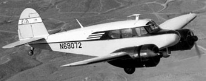
Dwane Wallace and his company perceived the untapped twin engine market as being for a relatively inexpensive and uncomplicated airplane. The prototype T 50 was a simple airplane. It had fixed ¬pitch props and small (225 hp) Jacobs en¬gines, but constant speed propellers and 20 more horsepower per side were later fitted. The props were not full feathering, and could only be pulled into full coarse pitch in the event of an engine failure. The design used al¬most no aluminum (only the nose cap, tail stinger, engine cowlings and nacelles) at a time when aluminum was far too valuable to waste on trainers. The T 50’s fuselage was welded steel tubing with fabric over wood longerons and formers, and the wing was all wood spruce, mahogany and birch under fabric. The flaps were wood also, and they and the gear were both driven through bicycle -chain loops by a pair of electric motors in the belly. The screw jack actuator for the gear was non-reversible, so no down locks or up¬latches were needed. The landing gear retracts upward into the nacelles and remains partly exposed so that belly landings can be made with little or no damage if the flaps are up. An unusual feature of the Jacobs engine is that it operates on only one magneto, plus battery ignition. It is started on the battery, then switched to the mag. Both engines turn generators, and they run smoothly on ignition if a mag fails. The T-50 prototype makes its first flight with Dwane Wallace at the controls on March 26, 1939. The plane was certified in December 1939. By 1940, it was in production and ready for buyers. Cessna only had time to make a few commercial T 50s before rumors of war reached American ears. The Army showed a polite interest in the T 50 as a trainer for bomber pilots, and ordered 33 specially equipped T-50’s – at the time, the largest order in Cessna’s history. The Army’s new planes are designated AT-8’s. The Army Air Corps’ first Bobcats were AT 8s, and they were, in fact, the service’s first multi-engine trainers of any sort. The AT¬8 had 290 hp nine cylinder Lycomings in place of the civilian airplane’s seven cylinder 220kW / 245 hp Jacobs R-680-9 engines, plus the eyebrow windows and transparent cockpit roof that henceforth all military T 50s would have. Service trials showed that these were unnecessarily powerful for use in a two-seat trainer, and when in 1941 the first real production contracts were placed, less powerful engines by the same manufacturer were specified. The British decided to ship their students to Canada for flight instruc¬tion, so it fell to Canada to come up with the necessary training planes. Prior to that, they’d sold four to the CAA [as airways fa¬cility check planes] and 33 to the Air Corps, but the big sale was the first 180 airplanes to the Canadians dubbing them “Cranes”. The Canadians called the T¬50s Cranes and eventually got 830 airplanes. One extra thing the Canadians wanted was a third fuel tank, installed in the fuselage be¬neath the rear seat; the two 60 gallon wing tanks were only good for about three hours, and 40 gallons in the fuselage gave the Crane an extra hour or so. The Crane wasn’t certified for civilian use with the third tank, and the filler cap opening was covered over in surplus Canadi¬an T 50s (and later U.S. versions that also got the mod) after the war. The Canadians soon reverted to wooden fixed pitch props, because of a lack of metal for blades and perhaps because they figured the airplane was going nowhere but down anyway if an engine stopped. For the Commonwealth Joint Air Training Plan, eventually 550 aircraft were supplied under Lend-Lease. The original use of Cessna’s T-50s had been in a light transport role, and in 1942 the USAAF decided that these aircraft would be valuable for liaison/communication purposes and as light personnel transports. The aircraft were named Bobcat and given the designation C-78, later changed to UC-78. In addition, a small number of commercial T-50s were impressed for service with the USAAF under the designation UC-78A.
The USAAF’s requirement for the two-seat conversion trainers had been difficult to predict, and when it was discovered in late 1942 that procurement contracts very considerably exceeded the training requirement, Cessna was requested to fulfil the outstanding balance of the AT-17B and AT-17D models as UC-78B and UC-78C Bobcats respectively. Both were virtually identical, but differed from the original UC-78s by having two-blade fixed-pitch wooden-propellers and some minor changes of installed equipment. Production of these two versions amounted to 1,806 UC-78Bs and 327 UC-78Cs. (3,370 UC-78 Bobcats for the USAAF in total)
The initial production version, designated AT-17, was equipped with Jacobs R-755-9 engines driving wooden propellers. A total of 450 was built, and these aircraft were followed into production by 223 of the generally similar AT-17A, which differed by having Hamilton-Standard constant-speed metal propellers and a lighter maximum weight. The later AT-17B (466 built) had some equipment changes, and the AT-17C (60 built) was provided with different radio for communications. Of these 1,199 aircraft, 550 were delivered to Canada with the name Crane Mk 1A. They came in two gross weights, de¬pending on the wing construction used¬ – 5,100 and 5,700 pounds and their crew capacity was either two or five, depending on whether they had the fuselage aux tank.
In the period 1942-3, the US Navy had a requirement for a lightweight transport aircraft to carry ferry pilots between delivery points and their home bases, as well as for the movement of US Navy flight crews. This led to the procurement of 67 aircraft, generally similar to the UC-78, which entered service under the designation JRC-1. Many examples of USAAF Bobcats remained in service for two or three years after the end of World War II. Originally built with 245 hp Jacobs radial engines, some Bobcats later got 295 hp Lycomings, and others were re-engined with 300 hp Jacobs powerplants. With the addition of an exit-hatch window to meet safety requirements, some also have been converted to six-seaters, though normal seating is two pilots and three passengers on a single bench-type rear seat.
Bobcats have a large rudder, but the vertical stabilizer is small and minimum single-engine control speed is 90 mph. At 10,000 feet, full throttle gives 20″ of manifold pressure, and 1,900 rpm on the Hamilton Standard constant-speed props will yield 143 mph indicated.
Cessna AT-17 / T-50 Bobcat
There are four different single engine ceilings listed for the heavier of the two versions of the airplane, based on gross weights of 5,400 and 5,700 pounds, each calculated with fixed pitch and constant speed props. The best is 1,500 feet above sea level; the worst is sea level, with a minimum rate of descent of 50 feet per minute. There were several little ¬known Bobcat variants and derivatives, though none of them ever progressed much beyond the prototype stage. The first was the Cessna P 7, a Bobcat with plywood covered wings and tail surfaces and 330 hp Jacobs engines. The second was the P 10, a Wichita mini-version of the de Havilland Mosquito, it was a two place P 7, with the big Jacobs en¬gines and a plywood covered fuselage, a little snub nose and a pair of side by side seats un¬der a bubble windscreen and roll back cano¬py. Finally, there was the P 260, which had the Bobcat’s wing planform, fabric covered fuselage arrangement and formation of boil¬ers nacelles; but it was a 14,000 pound car¬go hauler with R 1340 Pratt & Whitneys. It almost made it into production the Govern¬ment was about to buy 500 of them as C¬106As except the C-47 turned out to be more useful than any¬body had expected. In early 1944, Cessna suspends production of the Bobcat and begins manufacturing components for the Douglas A-26 and Boeing B-29 bomber. More than 5400 T-50s were constructed for the RCAF and the US military.
Cessna UC 78 Bobcat Engine: 2 x Jacobs R 755-9, 242 hp Length: 32 ft 9 in / 9.98 m Height: 9 ft 11 in / 3.02 m Wingspan: 41 ft 11 in / 12.78 m Wing area: 295.041 sqft / 27.410 sq.m Max take off weight: 5699.9 lb / 2585.0 kg Weight empty: 3501.5 lb / 1588.0 kg Max. speed: 170 kts / 314 km/h / 195 mph Cruising speed: 152 kts / 282 km/h Service ceiling: 22,000 ft / 6705 m Wing load: 19.27 lbs/sq.ft / 94.00 kg/sq.m Range: 652 nm / 1207 km / 750 miles Crew: 2 Passenger: 3
UC-78 Bobcat Engine: 2 x Lycoming R-680-9 radial, 220-kW (295-hp).
JRC-1 Engine: 2 x Lycoming R-680-9 radial, 220-kW (295-hp).
Crane Mk I Engine: 2 x Lycoming R-680-9 radial, 220-kW (295-hp).
Crane Mk 1A
AT-8 Engine: 2 x Lycoming R-680-9 radial, 220-kW (295-hp).
AT-17 Engines: 2 x Jacobs 8-775-9, 183kW (245 hp). Wingspan: 12.80m (41 ft 11 in). Length: 10m (32ft 9in). Max TO weight: 2258 kg (5,700 lb). Gross weight: 5,700 lb. Empty weight: 4,050 lb. Fuel capacity: 120-160 USG. Max speed: 195 mph at sea level. Cruise: 165 mph. Landing speed: 65 mph. Initial climb rate: 1,525 fpm. Ceiling: 15,000 ft. Operational range: 750 miles. Seats: 4-6.
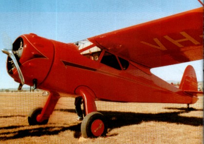
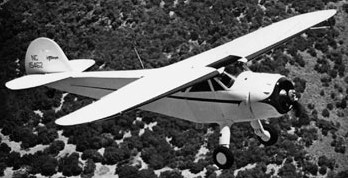
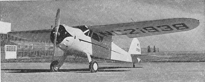
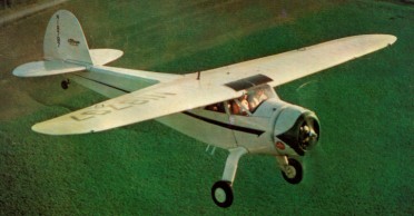
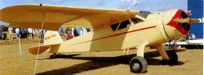
The final pre-war Cessna four-seat models were the C-145 and C-165 Airmaster. By the time their manufacture ceased in 1941, production had comprised 34 C-165s and three of the C-165D, powered respectively by 123kW and 130kW versions of the Warner Super Scarab.
The C-145 Airmaster was basically a modified C-34 featuring revised flaps and a wider gear. In 1932, the Airmaster was made available with the 165-hp Super Scarab, and the line continued in production until 1942. Forty-two were built.
Engine 145-hp Warner Scarab radial Wingspan: 34 ft 2 in Length: 24 ft 8 in Gross wt. 2,450 lb. Empty wt. 1,380 lb. Top 162 mph. Cruise 150 mph at 8200 ft Stall 50 mph. Initial climb rate 1,000 fpm. Range 472-785 miles. Ceiling 18,000 ft. Seats 4.
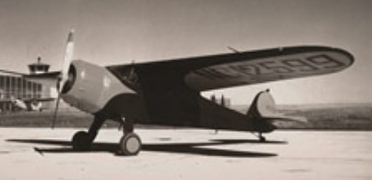
A prototype of the C-38 is unveiled on October 11, 1937. It becomes the first Cessna airplane to be called the Airmaster. The 1938 Model C-38 again featured minor improvements, with some of the previously optional equipment fitted as standard; airframe changes included the provision of wider track landing gear and a large under-fuselage flap which served as an airbrake to reduce landing speed. It was very fast for its horse¬power – 140 to 150 mph with a 165 hp Warner, and it was the first of the small business planes with enough performance to be practical in instrument flying. Since the Airmaster came on late in the era, after suitable instruments and radios became available, most of them were equipped for weather flying and were instrumental in leading the way to really practical use of airplanes for business transportation. Production of the C-38 amounted to 16 aircraft.
C-38 Engine: 1 x Warner Super Scarab radial, 108kW Take-off weight: 1066 kg / 2350 lb Empty weight: 621 kg / 1369 lb Wingspan: 10.41 m / 34 ft 2 in Length: 7.52 m / 24 ft 8 in Height: 2.13 m / 6 ft 12 in Wing area: 16.81 sq.m / 180.94 sq ft Max. speed: 261 km/h / 162 mph Cruise speed: 230 km/h / 143 mph Ceiling: 5485 m / 18000 ft Range: 885 km / 550 miles
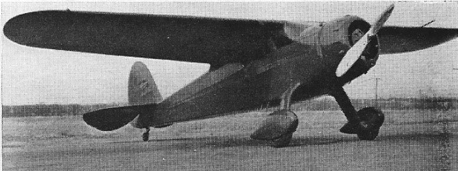
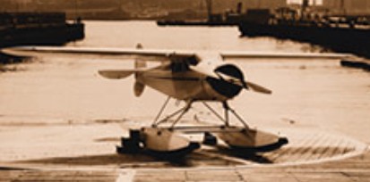
The C 34 success was followed by an improved version of the 34, the C 37, introduced in 1935. When equipped with Edo floats, it becomes the first Cessna model to receive seaplane approval. The Model C-37, introduced during 1937, brought in minor improvements to the furnishing of the cabin, which was widened by 12.7cm, and was fitted with electrically operated wing trailing-edge flaps. Some 46 C-37s were built, and one impressed in 1942 was designated UC-77C.
In 1933, Cessna was back in business again, this time with an improved version of the AW, featuring an improved landing gear and a 145-hp engine. This first model, designated the C-34, was possibly the most efficient airplane in its class, and nearly 100 were built.
The first production C-34 is sold in 1935.
C-34
Dwane Wallace, the nephew of Clyde Cessna, as a plant manager at no salary had the opportunity to design, build, test, fly, sell and race the company’s products. Wallace designed the C 34, a high-wing, four place cabin monoplane with a 108kW / 145 horsepower Warner Super Scarab engine. The airplane retained the fully cantilevered wing of earlier Cessnas but added flaps.
In June 1935 the prototype Model C-34 first flew, piloted by George Harte. It was capable of achieving a maximum speed of 261km/h. Wallace flew the C-34 for more than 4,000 hours in its first five years, including a trip to Mexico where it reportedly averaged 17 miles per gallon.
C-34
Among its racing wins was the Detroit News Trophy for “The World’s Most Efficient Airplane.” Eldon Cessna first won the race in 1931 in a Cessna model AW, after which was shut down due to the depression. However, four years later, it was restarted in 1935, and Cessna test pilot George Harte won the race, followed by another Cessna win in 1936. This triple-win meant that Cessna was allowed to keep the trophy permanently, and the C-34 was designated the world’s most efficient aircraft.
Forty-two were built, two being impressed for USAAF under the designation UC-77B.
The Cessna CR-3 custom racer makes its first flight on June 11, 1933. The plane wins the 1933 American Air Race in Chicago and later sets a new world speed record for engines smaller than 500 cubic inches by averaging 237.4 mph.
Johnny Livingston of “Seagull” fame had a CR-3 specially built for him with retractable landing gear, a cantilever wing and a 145 hp Warner engine. It was successfully flown by Johnny Livingstone in every race he entered in 1933.