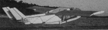
Design begun in 1966 and first first flown in October 1970, the Flightsail VII can either be towed behind a 70-hp ski boat or it can have a 90-hp Continental pylon mounted above the fuselage to fly the Flightsail under its own power. The structure is built from bolted aluminum, foam and epoxy. This two-seater amphi¬bian features twin booms and twin tails.
The company’s four-seat C4 project has slowed down its planned U.S. certification schedule to take advantage of anticipated streamlining of the Part 23 process by FAA, so deliveries could slide into 2015.
Flight Design entered receivership in 2016. Work on the C4 had come to a standstill after the company ran into financial difficulty. Production had also slowed to a trickle as the company workforce was trimmed to 10 people in Germany and around 60 in the Ukraine.
Flight Design completed the sale of all major company assets to the German investment group Lift Holding, allowing for the resumption of work on the C4, a Part 23-certified four-seater with a projected selling price of $250,000.
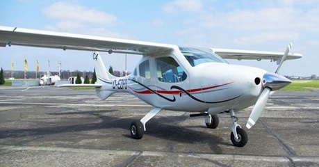
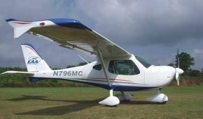
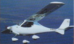
Created to complement the existing CTsw and CTLS, the MC offers utility and performance in a metal airframe. Constructed from Aluminum, steel and composites, the MC features a steel space frame, all aluminum flying surfaces and a composite cabin and cowling. The focus with the MC was to provide more utility with a giant cabin and easy-to-maintain modular construction. Designed with training and commercial fleet uses in mind, the MC visibility, baggage area and easy cabin entry are features. The metal flying surfaces of the MC are buck riveted and corrosion proofed for maintenance free flying. The steel pilot cage is covered with easy to remove composite shells to allow quick access to the landing gear and controls for annual or 100 hour inspections. The main landing gear is the Flight Design nobounce composite gear introduced on the CTLS. The cabin of the MC has a width of nearly 52 inches, 2-way adjustable seats and extra-wide cabin doors. The four-point safety harnesses, wing located fuel tanks and the BRS 1350 parachute system are standard. Standard features include 2 blade composite propeller, conventional three-axis controls, electric pitch trim system, cabin door gas struts, two large capacity baggage compartments, two cockpit storage compartments, electric pre-selector flap system, one piece molded windshield, steerable nose wheel, hydraulic brakes, durable, two-part urethane paint.
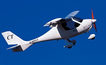
An ultralight composite aircraft, the Flight Design CT2K has been developed, and now has less weight, increased power and higher performance, with additional load-carrying capability. The design of the wing and the aircraft structure has been tested for a take-off weight up to 600 kg, so the Flight Design CT2K can comply with different certification criteria in different countries. 2009 CT2K price: 55862 EURO In spring 2003 CT2K was complimented with the CTSW (CTSW = CT Short Wing). Due to 80 cm shorter wings and increased ground effect CTSW has even greater aerodynamic stability and is easy to land. This aircraft had 5 km/h increased maximum level-flight speed while having slightly reduced climb speed. Both CT2K and CTSW were also available as VLA versions. 2009 price for the CTSW was 60000 EURO.
CT 180
In 2012 Flight Design had 11 registrations in the US. CTLSi (with the fuel-injected Rotax 912iS engine) are selling well, and the CTLS, MC and CTLS-Club models continue in the popular lineup. 2012 Prices: US$156,500 (CTLSi); US$143,800 (CTLS); US$136,860 (CTLS-Club).
CTLS
CT 180 Engine: Rotax 912, 80 hp Wing span: 9.30 m Wing area: 10.80 sq.m MAUW: 450 kg Empty weight: 275 kg Fuel capacity: 100 lt Max speed: 225 kph Cruise speed: 210 kph Minimum speed: 64.4 kph Climb rate: 5 m/s Certification: VZ Seats: 2 Fuel consumption: 15 lt/hr Price (1998): 60 000 DM
Flight Design CT Engine: Rotax 912S, 100@SL TBO: 1500 hrs. Fuel type:100/100LL Propeller: Neuform FP Landing gear type: Tri./Fixed Max ramp weight: 1320 lb Gross weight: 1320 lb Landing weight: 1320 lb Empty weight, std: 646 lb Useful load, std: 674 lb Useful fuel, std: 34 USgals Payload, full std. fuel: 470 lb Wingspan: 28 ft Overall length: 20 ft. 4 in Height: 7 ft. 11 in Wing area:107 sq. ft Wing loading: 12.3 lbs./sq. ft Power loading: 13.2 lbs./hp Wheel size: 6.00 x 6 in Seating capacity: 2 Cabin doors: 2 Cabin width: 49 in Cruise speed 75% power: 112 kt Max range (w/ reserve) 75% power: 600 nm Fuel consumption 75% power: 4.5 USgph Vso: 39 kt Best rate of climb SL: 960 fpm Service ceiling: 14,000 ft Takeoff ground roll: 295 ft Takeoff over 50-ft. obstacle: 525 ft 2006 price: US$92,900
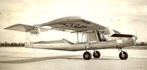
The FL-23 prototype was designed and built as a private venture, it was a high-wing cantilever monoplane with an all-moving tailplane mounted at the top of the fin. It had a fixed tricycle landing gear and powered a 225-hp (168 kW) Continental E225 piston engine. It had room for a pilot and observer in tandem; the observer had an unusual acrylic plastic enclosure to give an all-round visibility.
The US Army issued the specification for a two-seat liaison and observation monoplane and the prototype was entered into the competition. During trials the aircraft was badly damaged in a flying accident when it lost its tail, and was withdrawn from the competition. The competition was won by the Cessna 305A which became the L-19 Bird Dog.
Powerplant: 1 × Continental E225, 235 hp (175 kW) Propeller: Hartzell 7 ft (2.1 m) diameter Wingspan: 33 ft 4 in (10.16 m) Length: 28 ft 4 in (8.64 m) Height: 8 ft 1 in (2.46 m) Wing area: 277 sq ft (25.7 m2) Airfoil: NACA 4412 Empty weight: 1,500 lb (680 kg) Gross weight: 2,450 lb (1,111 kg) Fuel capacity: 60 US gal (50 imp gal; 230 L) Maximum speed: 133 mph (214 km/h, 116 kn) Cruise speed: 118 mph (190 km/h, 103 kn) Stall speed: 38 mph (61 km/h, 33 kn) (flaps extended) Range: 485 mi (781 km, 421 nmi) Service ceiling: 19,500 ft (5,900 m) Rate of climb: 1,180 ft/min (6.0 m/s) Crew: 2
John Thorp was interested in armed light aircraft and in 1948 he demonstrated the prototype Sky Skooter at Fort Bragg. At the start of the Korean conflict Thorp sold his basic armed lightplane concept to Wendell and Maurice Fletcher. The result was the FD-25 series. Developed by the Fletcher brothers and John Thorp it was aimed at a perceived need in the US armed forces for a cheap and lightweight counter insurgency (COIN) attack aircraft.
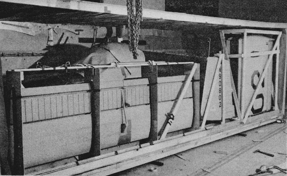
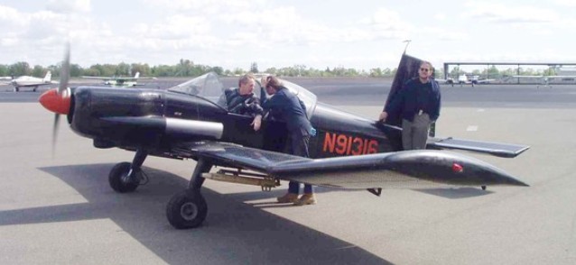
The prototype FD-25, N90802, received the green light from the Fletcher management on 1 November 1950. Five engineers, including Thorp, and five engineers were assigned to the project. The prototype flew on 14 April 1951. The single seat FD25 was manufactured from Dow magnesium rather than aluminium. According to Thorp was “economically marginal because of the extra processing, equivalent to anodising, that was required to resist corrosion”.
Prototype magnesium FD-25 Marine HQ, Quantico, Virginia. Pilot Roy Cusick.
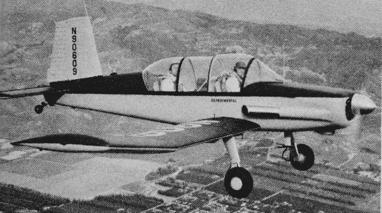
The FD-25A two-place version was begun before the single-place flew. The aircraft, N90609, had a magnesium wing and aluminium fuselage. Heavy navigation equipment resulted in a critical aft c-of-g condition that contributed to the FD25A crashing during flight trials in 1952, killing several Fletcher employees.
FD-25A – pilot Roy Cusick, engineer Leland Lord. Both were killed in the plane
It was the two-place version that was built in Japan.
Protype FD-25 crated for shipment to Toyo Aircraft in Tokyo, Japan
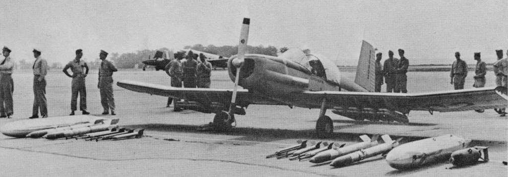
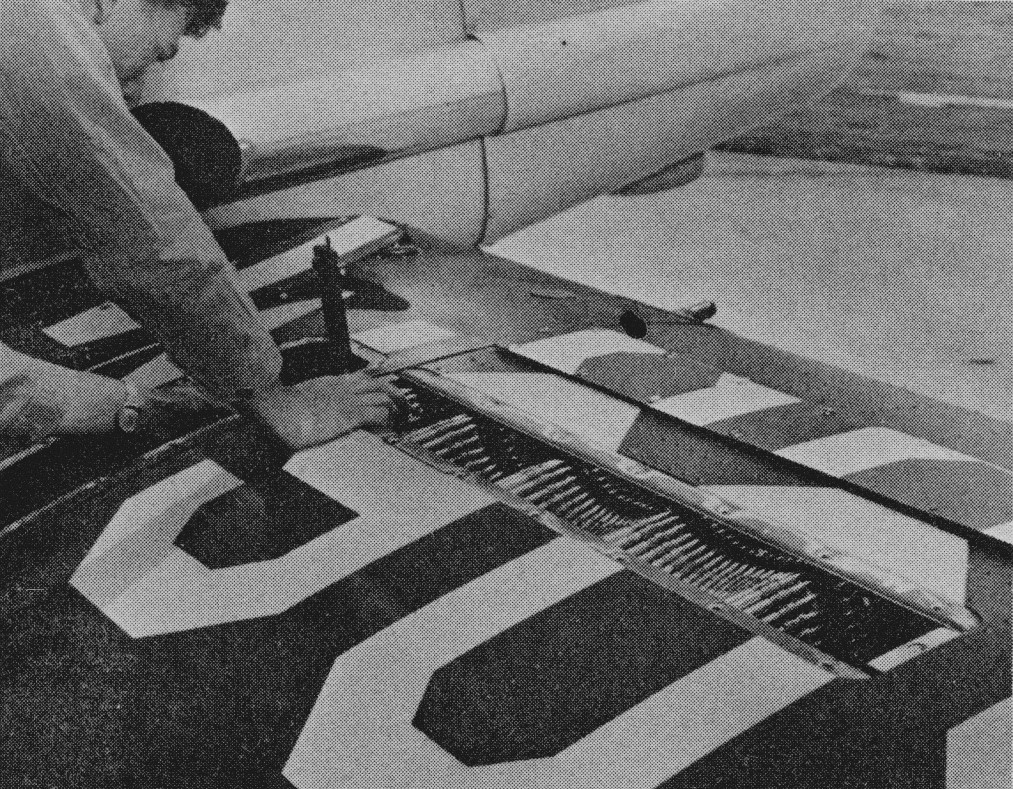
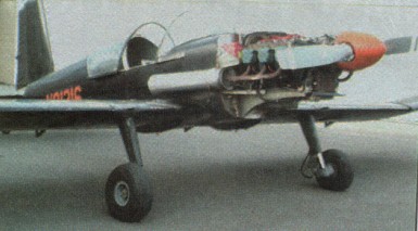
Fletcher then took nine months to complete the all-aluminium FD-25B N91316. Two 30-calibre machine guns were imbedded in the wings, mounted outboard of the fuel cells and firing outside the propeller arc procured on bailment from the office of Admiral Richardson, then Chief of Naval Aviation. Each gun had space for 1000 rounds of ammunition.
Thorp, who made the initial flights in all the FD-25s, also fired the first in-flight rockets on the range at Inyokern, California. In preliminary ground firing, the cap on the back of the 5-in HVAR rockets ejected with such force that it damaged the stabiliser. The rocket rails were then moved farther outboard.
The plane was to depend on surprise attack and was built without armour plate or self-sealing tanks. The FD-25 was created to stop Russian T-36 tanks used by the North Koreans.
The FD25B undertook very successful demonstrations with the US armed forces. The FD25B was a performer and was enthusiastically supported by US military personnel but unfortunately received no US Government support.
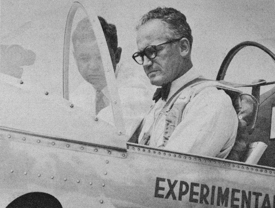
Senator Barry Goldwater flew the experimental FD-25B solo, as did Chuck Yeager.
Senator Barry Goldwater in the FD-25B, Washington-Virginia airport in 1953.
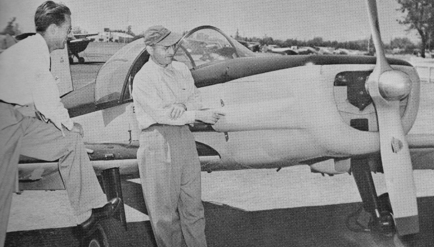
Circa 1951, John Thorp (right) and Don Downie with prototype FD-25. The fixed pitch propeller was later changed to a Hartzell controllable.
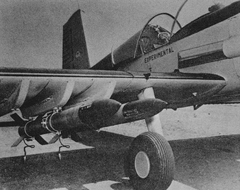
The FD25B armament consisted of a pair of wing mounted racks for two 33-gallon napalm tanks. Additionally two 250 lb. fragmentation bombs and up to 40 2.75 inch folding fin air rockets of four 5.0 inch heavy rockets or twenty 80 mm Oerliken rockets could be fitted.
Fletched ceased production after three examples to then concentrate on the development of the FU-24. However, further FD25 production was undertaken under license in Japan by the Toyo Aircraft company.
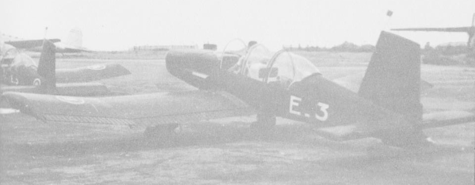
The first Toyo example, a FD25B, was flown in March, 1953 and soon after sales of four FD25A and four FD25B were made to the Royal Cambodian Air Force. These were followed by an unclear number, possibly two each FD25A and FD25B, to the North Vietnamese Air Force. The fate of these airframes is unknown.
Cambodian Air Force FD-25
Much of the demonstration life of the FD-25B was flown with a full dull black paint job. The FD-25 was designed to sell originally for $25,000 or less.
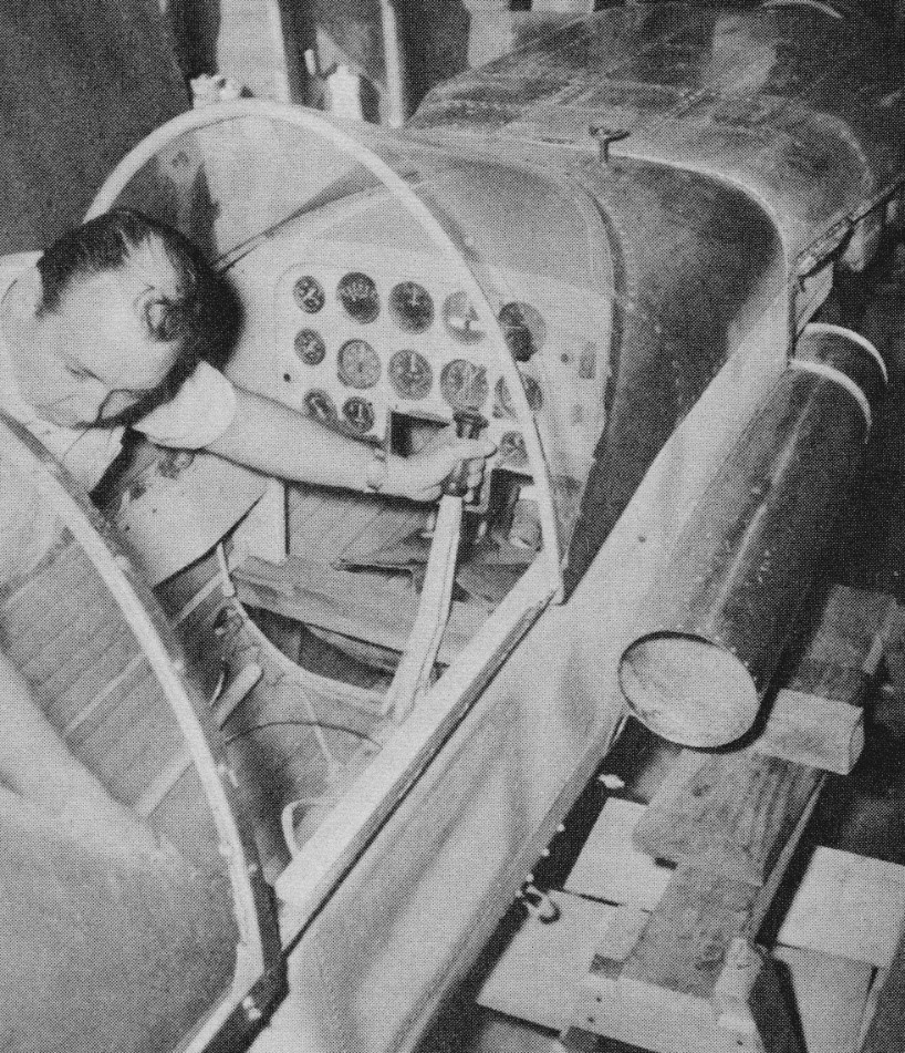
Ex-WW2 fighter pilot Jim Castor took over the FD-25 project after Don Downie and obtained the only known 25 in existence. He obtained it from the company after it had collected dust for eight years and refurbished it in his garage in La Mirada, California. Part of Castor’s agreement with Fletcher Aviation was to demonstrate the airplane to any potential customer on request.
Jim Castor inspects the FD-25B prior to re-assembly
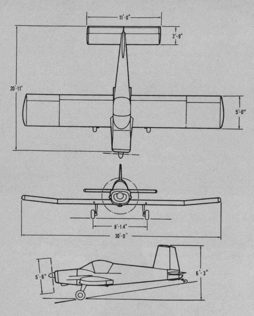
Engine: Continental E225-8, 225 hp. Wingspan: 30 ft Length: 20 ft 11 in Height: 6 ft 3 in Wing area: 150 sq.ft Empty weight: 1228 lb MTOW: 2500 lb Fuel capacity: 50 gal Max speed: 187 mph SL Cruise speed: 162 mph SL Service ceiling: 16,500 ft Range: 630 mi Armament: 2 x 0.30in mg Hardpoints for: 2 x 33 gal nalpalm, 2 x 250 lb bombs, 40 x 2.75in rockets, or 4 x 5in rockets
FD-25B Engine: Continental E225, 250 hp Propeller: Hartzell controllable pitch Wingspan: 30 ft Wing area: 150 sq.ft Airfoil: NACS 652-415 Aspect ratio: 6-1 Chord: 60 in Outer wing dihedral: 6 deg Length: 20 ft 11 in Height: 6 ft 3 in Gross weight: 2700 lb Empty weight: 1428 lb Useful load: 1272 lb Fuel capacity: 60 USG Max speed: 187 mph Cruise speed: 162 mph Landing speed: 45 mph ROC: 1725 fpm Service ceiling: 16,500 ft Cruise range: 630 mi Take-off distance: 500 ft Landing distance: 330 ft Fin area: 8 sq.ft Rudder area: 4 sq.ft Wlevator area: 9 sq.ft Stabiliser area: 21 sq.ft Seats: 1
Tomasz Fleger of Warsaw (who already designed in 1911 a floatplane and airship) designed and built a small monoplane pusher in 1914, which, however, never flew.
F-401 prototype, Golden Wings Museum, Blaine, Minnesota
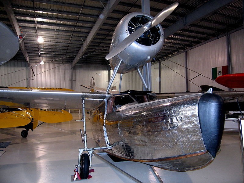
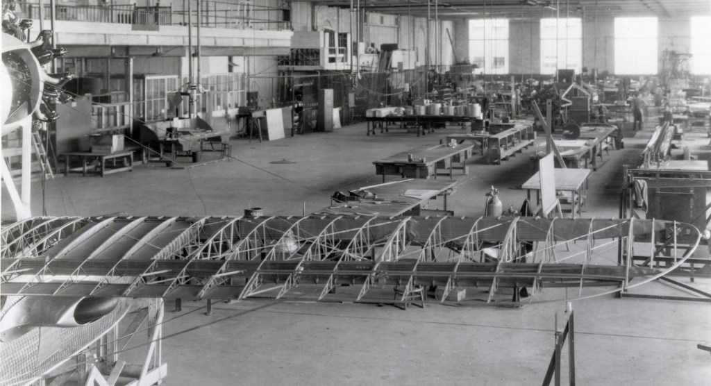
The Sea Bird was an amphibious utility aircraft designed in 1934–1935 by James C. Reddig for Fleetwings, Inc., of Bristol, Pennsylvania. While the aircraft’s basic configuration had a precedent in the design of the Loening “Monoduck” developed by the Grover Loening Aircraft Company as a personal aircraft for Mr. Loening (for whom Reddig worked from 1929 to 1933), the Sea Bird was unusual because of its construction from spot-welded stainless steel. It was a high-wing, wire-braced monoplane with its engine housed in a nacelle mounted above the wings on struts.
The pilot and passengers sat in a fully enclosed cabin.
First flying in 1936, Fleetwings initially planned to manufacture 50 production units, but at a price approaching $25,000 during the Depression, there proved to be no sustainable market and only five production F.5 Seabird were built.
The Sea Bird found use with private pilot owners and saw service with the oil support industry in Louisiana, including operation by J. Ray McDermott & Co.
Powerplant: 1 × Jacobs L-5, 285 hp (213 kW) Wingspan: 40 ft 6 in (12.34 m) Wing area: 235 sq ft (21.8 m2) Length: 31 ft 5 in (9.58 m) Height: 12 ft 6 in (3.81 m) Empty weight: 2,320 lb (1,052 kg) Gross weight: 3,450 lb (1,565 kg) Fuel capacity: 52 US gal (43 imp gal; 200 L) Maximum speed: 150 mph (240 km/h, 130 kn) at sea level Cruise speed: 133 mph (214 km/h, 116 kn) Range: 400 mi (640 km, 350 nmi) Service ceiling: 15,000 ft (4,600 m) Rate of climb: 900 ft/min (4.6 m/s) Crew: 1 Capacity: 3 passengers