A developments of the Fairchild M-62s appeared in the 1960s, the Funk F-23 built at Broken Arrow in Oklahoma and first flown in 1962. Eleven production aircraft were built around the PT-19 fuselage and powered by the 240-hp W670M Continental. A further three were built with 275-hp R-755 Jacobs engines.
In May 1970 Cosmic Aircraft Corp acquired all rights in manufacture of F-23 single-seat agricultural monoplane, produced previously by D. D. Funk Aviation Company Inc. Two models: F-23A (Continental radial) and F-23B (Jacobs radial). Production ceased 1975.
Monoplane
Funk A / Funk B / Akron Aircraft Co Model B
The first plane or Funk model ‘A’ was powered by and inverted and converted flat head four cylinder ingine.
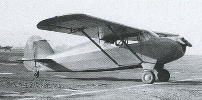
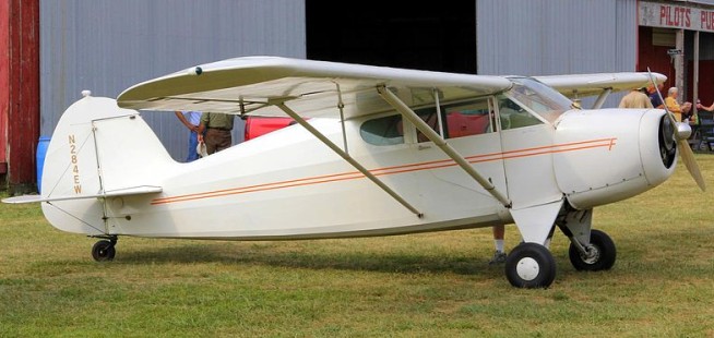
The Funk Model B was a 1930s American two-seat cabin monoplane designed by Howard and Joe Funk. Originally built by the Akron Aircraft Company later renamed Funk Aircraft Company.
The Model B was the first powered aircraft designed by brothers Howard and Joe Funk, whose previous experience was in homebuilt gliders and sailplanes. Similar in appearance to a Piper Cub, their Model B was a strut-braced high-wing monoplane with a conventional tail unit and fixed tailwheel landing gear. The design uses mixed construction with fabric covered wooden wings and a welded steel-tube fuselage. The aircraft was powered by the brothers’ own Model E engine developed from a Ford “B” motor-car engine. The prototype first flew in late 1933.
When the test flights proved to be successful the brothers formed the Akron Aircraft Company in 1939 to build the Funk B. After production began, the engine was changed to a 75hp (56 kW) Lycoming GO-145-C2 horizontally-opposed four-cylinder engine and was re-designated the Model B-75-L.
In 1941 the company moved from Akron to Kansas and the company was renamed the Funk Aircraft Company. Production was stopped during the Second World War and one aircraft was impressed into service in 1942 with the United States Army Air Corps as the UC-92.
After the war in 1946 production was resumed using a Continental C85-12 engine and the aircraft was redesignated the Model B-85-C and named the Bee. It did not sell well and production was halted in 1948. 380 aircraft of all variants had been built.
Variants:
Model B
Prototype and initial production aircraft with Funk E engine.
Model B-75-L
Pre-war production aircraft with a 75hp (56 kW) Lycoming GO-145-C2 piston engine.
Model B-85-C Bee
Post-war production aircraft with a Continental C85-12 engine.
UC-92
Army designation for one impressed Model B-75-L (s/n 42-79548).
Specifications:
B-85-C
Engine: 1 × Continental C85-12, 85 hp (63 kW)
Propeller: 2-bladed Lewis fixed pitch
Wingspan: 35 ft 0 in (10.67 m)
Length: 20 ft 1 in (6.12 m)
Height: 6 ft 1 in (1.85 m)
Wing area: 169 sq ft (15.7 sq.m)
Airfoil: NACA 4412
Empty weight: 890 lb (404 kg)
Gross weight: 1,350 lb (612 kg)
Fuel capacity: 20 US gal (76 l; 17 imp gal)
Maximum speed: 115 mph (185 km/h; 100 kn) at sea level
Cruise speed: 100 mph (87 kn; 161 km/h)
Range: 350 mi (304 nmi; 563 km) with 30 minutes reserve
Service ceiling: 15,000 ft (4,572 m)
Rate of climb: 800 ft/min (4.1 m/s)
Take-off run: 348 ft (107 m)
Crew: 2
Fumat 1911 monoplane
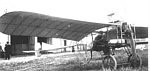
The 1911 Fumat monoplane was designed and built by Victor Fumat in France.
Span: 26’3″
Length: 26’3″
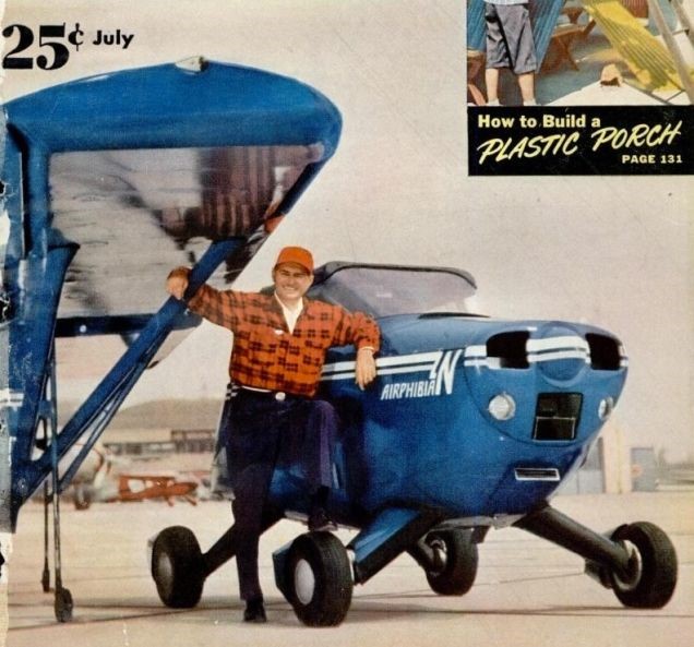
Fulton FA-2 Airphibian / FA-3 Airphibian / Continental Inc Airphibian / FA-2 / FA-3
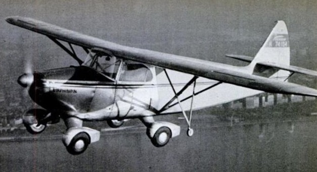
Robert Edison Fulton, an engineer of Danbury, Connecticut, in 1946 built a roadable aircraft which entered production, albeit only in very limited numbers, as the first fully licensed flying automobile in the United States.
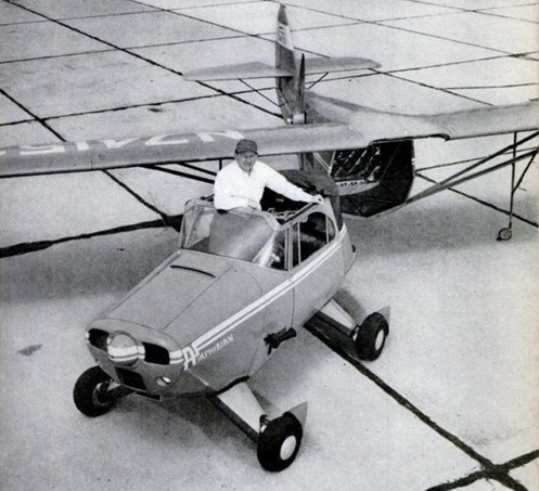
His Airphibian was a four wheeled, two seat, high wing monoplane with a removable airframe which could be rolled away on its own retractable wheels after disconnection, leaving an aluminium bodied soft top coupe car.
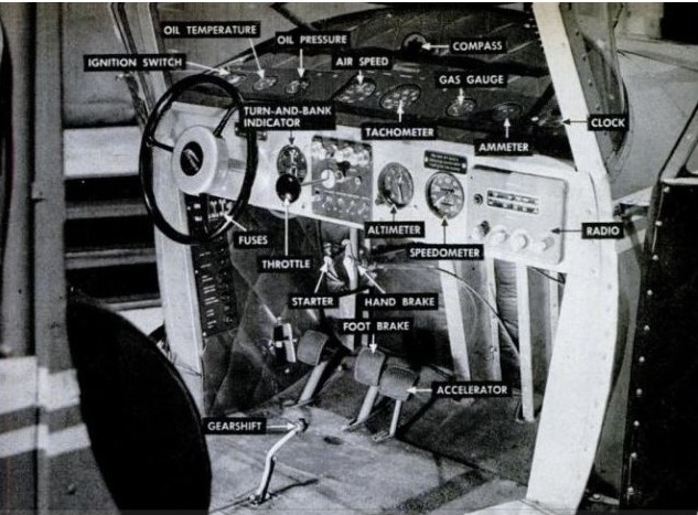
Fulton used a 165 hp Franklin aero-engine for air and road drive, with automatic hook up of all flying controls. The aircraft’s rudder pedals became brake and accelerator in the car, while landing lights doubled as headlamps. A safety device prevented the engine starting with the propeller installed unless all flying controls were connected and locked.
The airphibian was used extensively on business and pleasure trips.
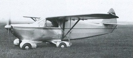
The prototype Airphibian flew on November 7,1946, and was certificated in December 1950 as the Fulton Model FA-2 Airphibian. A production model, designated FA-3, appeared in 1954.
Life magazine published a photo story of a flying visit to the theatre by the Fultons, who flew 100 km (62 miles) from their Connecticut home to New York’s La Guardia Airport at 180 kph (110 mph), unhitched the aircraft portion and drove across town to Broadway, all in less than an hour. A fabric top was buttoned from the windscreen for driving in bad weather.
So successful was the Airphibian that Fulton announced in 1949 that he would build production versions for sale at $7000 to $9000 each. ‘It flew fine,’ a test pilot reported during the Airphibian’s certification trials, ‘and it drove well, too, but it just didn’t perform in the air because of all that weight and drag.’ By 1950 the first three Airphibians had been driven over 322,000 km (200,000 miles) and made more than 6000 car/plane transformations. In all eight were built before Robert Fulton sold the rights to the design to private investors who never pursued it.

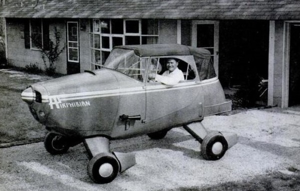
The Fulton FA-3 Airphibian two-place, powered by a 160 hp Franklin engine featured improvements including cantilever wings and outrigger wheels, which support the wings when detached, which retract. They were fixed in previous types.

Fulmar HP-16 Héron
Single seat single engined high wing mono¬plane with two axis control. Wing has unswept leading and trailing edges, and constant chord; cruciform tail. Pitch control by eleva¬tor on tail; yaw control by fin mounted rudder; control inputs through stick for pitch/yaw/roll. Wing braced from below by struts; single surface. Undercarriage has three wheels in tricycle formation; no suspension on any wheels. Push right go left nosewheel steering indepen¬dent from yaw control. Optional brake on nosewheel. Aluminium tube framework, without pod. Engine mounted below wing driving pusher propeller.
The MP 16 Heron was designed by Pierangelo Mez¬zapesa, the driving force behind Fulmar. The prototype made its first flight on the 1 February 1983, and became available from April 1983 with two engine options: Sachs 330cc (see per¬formance characteristics below) or Hirth F 263R of 383 cc, which develops at 3900 rpm, an equivalent power (23 hp) to the Sachs. Despite the solidity of its tubular structure, the MP 16 Heron is foldable for transport on a road trailer, its space requirement then being 16.5 x 5.9 x 5.9 ft (5 x 1.74 x 1.75 m). A side by¬side two seater version is at the design stage.
Length overall 16.5 ft, 5.00 m.
Height overall 6.7ft, 2.00m.
Wing span 32.1ft, 10.0m.
Constant chord 4.7ft, 1.40m.
Dihedral 5 deg.
Sweepback 0 deg.
Tailplane span 8.2 ft, 2.50 m.
Total wing area 151 sq.ft, 14.0 sq.m.
Fin area 5.4 sq.ft, 0.50 sq.m.
Rudder area 14.0 sq.ft, 1.30 sq.m.
Tailplane area 13.5 sq.ft, 1.25 sq.m.
Total elevator area 9.2 sq.ft, 0.85 sq.m.
Wing aspect ratio 7.1/1.
Wheel track 5.9ft, 1.75m.
Nosewheel dia¬meter overall 12 inch, 30cm.
Main wheels diameter overall 16 inch, 40cm.
Engine: Sachs SA 340 engine.
Max power 22hp at 5250rpm.
Propeller diameter and pitch 41 x 18 inch, 1.05 x 0.46 m.
No reduction.
Max static thrust 155 lb, 70 kg.
Power per unit area 0.15hp/sq.ft, 1.6hp/sq.m.
Fuel capacity 2.6 US gal, 2.2 Imp gal, 10.0 litre in main tank; 5.3 US ga1, 4.4 Imp gal, 20.0 litre in reserve.
Empty weight 1991b, 90kg.
Max take off weight 419 lb, 190kg.
Payload 220 lb, 100kg.
Max wing loading 2.78 lb/sq.ft, 13.6 kg/sq.m.
Max power loading 19.1 lb/hp, 8.63 kg/hp.
Load factors design; +6.0, 3.0 ultimate.
Max level speed 44 mph, 70 kph.
Never exceed speed 50 mph, 80kph.
Max cruising speed 37mph, 60kph.
Economic cruising speed 34mph, 55kph.
Stalling speed 20 mph, 32 kph.
Max climb rate at sea level 300 ft/min, 1.5 m/s.
Min sink rate 400 ft/min at 31 mph, 2.0 m/s at 50 kph.
Best glide ratio with power off 7/1 at 34 mph, 55kph.
Take off distance 115 ft, 35 m.
Land¬ing distance 66 ft, 20 m.
Service ceiling 6560 ft, 2000 m.
Range at average cruising speed 50 mile, 80km.
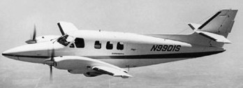
Fuji FA-300 / Rockwell Commander 700
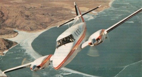
Fuji heavy industries and Rockwell International joined forces to manufacture a seven passenger pressurized twin that will be called in the US the Rockwell Commander 700.
But in order to compete directly in the American marketplace, Fuji needed a dealership organization that could both sell and service the airplane.
Rockwell’s problem was their Aero Commander basic design of 30 years had run out of growth potential.
The resulting agreement: Fuji builds the airframe, wings and tail assembly in Japan, then ships them to Rockwell’s Oklahoma plant, where they are assembled and fitted with engines, landing gear, interiors and other American-made components, which make up approximately 80 percent of the complete airplane. The design is certificated in both countries; Fuji will market the airplane in Australia and Asia, while Rockwell, through its dealer network, will sell the Commander 700 in America and Europe.
The first of five flying prototypes of the Fuji FA 300/Rockwell Commander 700 made its maiden flight at Utsonomiya on 13 November 1975 and the first flight in the U.S. was in late February 1976.
Three air¬planes were involved in U.S. certification, and two in a companion pro¬gram in Japan. The Rockwell Commander 700 was certified by Japan in 1975. It features two 340 hp turbocharged Lycomings. First deliveries of the 700 were scheduled for February 1977.
The 700 is a pressurized piston twin powered by two Lycoming TIO 540s that put out 340 horsepower at 2,500 rpm and have a TBO of 1,800 hours; they’re geared and turbocharged and are much the same engines Piper uses in the Navajo Chieftain. Their cooling is updraft, with air exiting out the upper rear of each nacelle through a single mo¬tor driven cowl flap that opens inward. Each wing carries 624 pounds of fuel in a single tank that supplies gas directly to its respective engine. The remainder of the fuel system is comprised of two shutoff valves, a single cross flow valve for emergency situations and two boost pumps. Pressurization was 5.5 psi, for a 5,000 foot cabin at 20,000 feet. The cabin is large 360 cubic feet including 53 cubic feet for baggage in the pressurized area.
On the first flight, a cruising speed of about 200 knots was attained at 10,000 feet. Preliminary figures indicate a top speed of 240 knots at 20,000 feet. Total fuel capacity will be 190 gallons, for an en¬durance of about five hours.
The airframes will be fabricated in Japan and shipped to Rockwell’s Bethany, Oklahoma plant. Engines, systems, accessories, avionics and interiors will be installed there as the airplane is assembled. Eighty percent of the total aircraft will be of U.S. manufacture.
Development of the airplane started in the mid 1960s, with Rockwell entering the picture in the early 1970s. The specifications were refined, discussed and negotiated, and an agreement as to the final design for the 700 was reached in June 1974.
The airfoil section was designed by Fuji and combines with an efficient flap system to produce a relatively low stalling speed in spite of a relatively high wing loading. The 700 has 200 square feet of wing area and the projected gross weight is 6,800 pounds.
An extensive wind tunnel program was conducted on the design. Engine cooling drag has been minimized, and extensive use of metal bonding has resulted in smooth surfaces.
Rockwell and Fuji Jet Industries terminated their agreement on the Commander 700 in December 1979.
Aerostar Aircraft Corp acquired the design and production rights to Aero Commander.
Rockwell Commander 700
Engines: Lycoming TIO 540 R2AD, 340 hp at sea level.
TBO: 1,800 hrs.
Props: three blade, constant speed, 81 in diameter.
Length: 38 ft. 2 in.
Height: 13 ft. 4 in.
Wingspan: 42 ft. 5in.
Wing area: 200 sq.ft.
Wing loading: 33.8 lb/sq.ft.
Power loading: 9.9 lb/hp.
Seats: 6.
Empty weight: 4,740 lbs.
Useful load: 2,010 lbs.
Payload with full fuel: 762 lbs.
Gross weight: 6,750 lbs.
Usable fuel capacity: 208 USG/1,248 lbs.
Maximum landing weight: 6,600 lbs.
Maximum rate of climb: 1,633 fpm.
Single engine rate of climb: 273 fpm.
Single engine climb gradient at 101 kts. (Vyse): 256 ft/nm.
Service ceiling: 32,000 ft.
Certificated ceiling: 25,000 ft.
Single engine service ceiling: 12,000 ft.
Maximum speed: 221 kts.
Max cruise, 75 % power at 24,000 ft: 218 kts.
Econ cruise, 65 % power at 16,000 ft: 190 kts.
Duration at max cruise: 5.9 hrs.
Duration at econ cruise: 6.8 hrs.
Stalling speed, clean: 85 kts.
Stalling speed, full flaps: 67 kts.
Pressurization differential: 5.5 psi.
10,000 ft. cabin at: 26,000 ft.
Max SL cabin alt: 12,500 feet.
Aerostar 700
Engines: two 350hp Lycoming TI0-540-U2A
Wingspan: 36’8″
Length: 34’10”
Useful load: 1715 lb
Max speed: 328 mph
Cruise: 282 mph
Stall: 84 mph
Range: 1151 mi
Ceiling: 30,000′.
Seats: 4-6
Aerostar Super 700
Engines: 2 x modified Lycoming I0-540-SIA5
Seats: 4-6
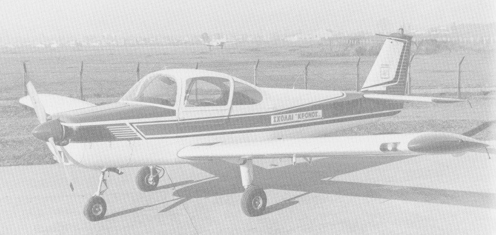
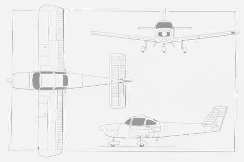
Fuji FA-200 Aero Subaru
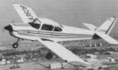
Fuji Heavy Industries builds a two seat aerobatic light trainer, the FA 200 Aero Subaru, of which over 250 have been sold in Japan and in Europe. Expensive to produce because of its heavy reliance on handwork and imported hardware, and rather homely in appearance, the Fuji has not been as great a success, but it has not been a failure.
The FA-200-160 is a basic version with a Lycoming O-320-D2A engine and certified as a two-seater (aerobatic category) and three-seater (utility) or four-seater.
The FA-200-180 was a developed version certificated as a two-seater (aerobatic category) and four-seater (utility and normal categories).
The FA-203S was an experimental STOL verion with leading-edge slats and full-span trailing-edge flaperons. Only one was built.
FA-200-180
Engine: Lycoming IO-380-B1B, 180 hp
Wingspan: 30 ft 11 in / 9.42 m
Length: 26 ft 2.25 in / 7.98 m
Empty weight: 1433 lb / 650 kg
MTOW NormCat, 4 seat: 2535 lb / 1150 kg
Max cruise 75% 5000 ft/1535m: 110 kt / 127 mph / 204 kph
ROC SL: 760 fpm / 232 m/min
Service ceiling: 13,700 ft / 4175 m
Range max fuel: 534 nm / 615 mi / 970 km
Seats: 4
Baggage capacity: 44 lb / 25 kg (shelf), 176 lb / 80 kg (compartment)
Cabin length: 5 ft 8.5 in / 1.74 m
Cabin width: 3 ft 4.5 in / 1.03 m
Fuji TL-1
Production of an uprated KM-2B four-seat aircraft for the JGSDF, the TL-1, was conducted.
Fuji LM-1 Nikko
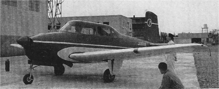
The Fuji LM-1 Nikko is a four-seat liaison aircraft adapted from the design of the Beech T-34 Mentor which was built under licence by Fuji for the Japanese Self-Defense Force.
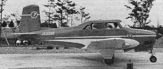
Flown for the first time on 6 June 1955, the LM-1 employs the wing, undercarriage and tail assembly of the Mentor, and a new centre fuselage.
Engine: 225 hp Continental O-470-13
Wing span: 32 ft 9.5 in
Wing area: 177.6 sq.ft
Length: 25 ft 11 in
Height: 9 ft 7 in
Empty weight: 2234 lb
Loaded weight: 3375 lb
Max speed: 185 mph
Cruise: 157 mph
Service ceiling: 17,399 ft
Fuji KM-2 / T-2 / T-5
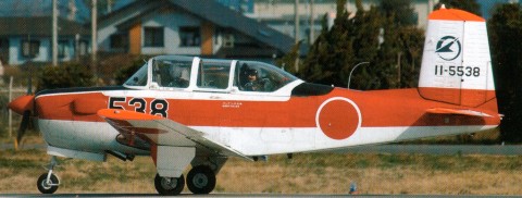
The original LM/KM series aircraft were four-seat developments of the Beech T-34A Mentor, the first flying in 1955, and large numbers were delivered to the JMSDF and JGSDF for liaison and training. A tandem two-seat derivative of the Beech T-34 with a Lycoming IGSO-480-AIA6 piston engine entered production in the mid¬1970s as the KM-2B for the JMSDF, and later as the T-3 for the JASDF. Fuji in Japan flew the prototype (JA3725) of the KM-2B two-seat primary trainer on 26 September 1974; this development of the earlier KM-2 combined the airframe and powerplant of that aircraft with the tandem-seat cockpit arrangement of the Beech T-34A Mentor.
Ten KM-2 were ordered for the JMSDF, for delivery by February 1963. Further contracts were to follow, to replace the 45 North American SNJs (Harvards) then in naval service. The prototype KM-2 received its certificate of airworthiness February 1961.

Fuji has tested a company owned four-seat KM-2 utility aircraft with an Allison 250-B17 turboprop, under the designation KM-2D.
The first KM-2D, flown on 28 June 1984, was a straight conversion of a company-owned piston KM-2 retaining the original four-seat cabin structure.
The JMSDF considered re-engining its fleet of tandem-seat KM-2B trainers, but has now elected to purchase new-build KM¬2Kais, with the first funded in 1986/87. These will be turboprop powered, and will retain the tandem seating of the KM-2B. Deliveries are scheduled for 1988, to begin replacement of the oldest KM-2Bs.
The Japanese Maritime Self-Defence Force took delivery of the definitive turbo-prop powered KM-2D prototype (first flown on 27 April 1988) in August 1988 which was to be tested by the service until March 1989. This prototype, a conversion of a MSDF KM-2B, embodied extensive cabin redesign.
KM 2
Engine: Lycoming IGSO-480 A1A6, 340 hp.
Max speed: 227 mph (365 kph) at 16,400ft (5000 m)
Cruise, 183 mph (295 kph)
Initial climb, 1,560 fpm (7.92 m/sec)
Service ceiling, 29,200ft (8900 m)
Range, 765 mls (1235 km).
Empty weight, 2387 lb (1083 kg)
Loaded weight, 3,296 lb (1495 kg).
Span, 32 ft 9.75 in (10 m)
Length, 26 ft 0.75 in (7.95 m)
Wing area, 177.6 sq.ft (16.49 sq.m).
KM-2B
Engine: Lycoming IGSO-480.
T-3
Engine: Lycoming IGSO-480
T-5
Engine: Allison 250B-17D.
