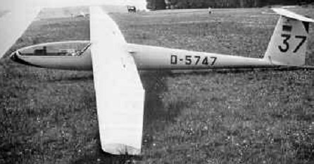
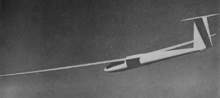
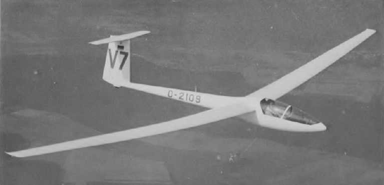
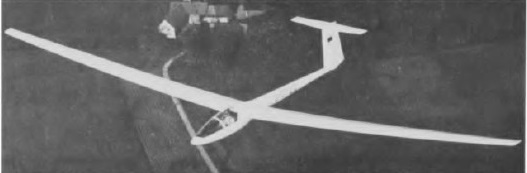
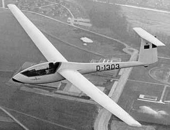
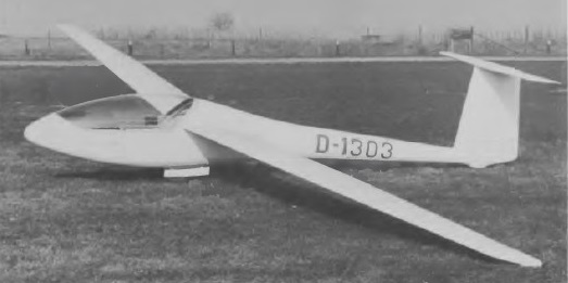
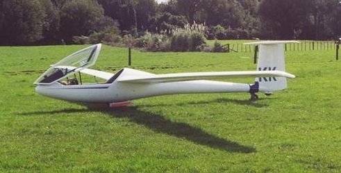
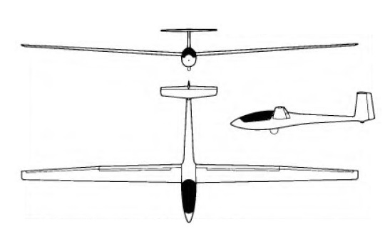
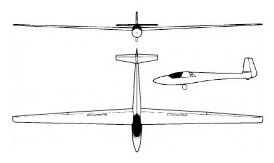
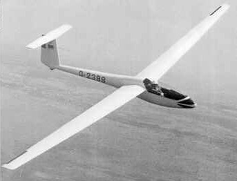
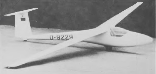
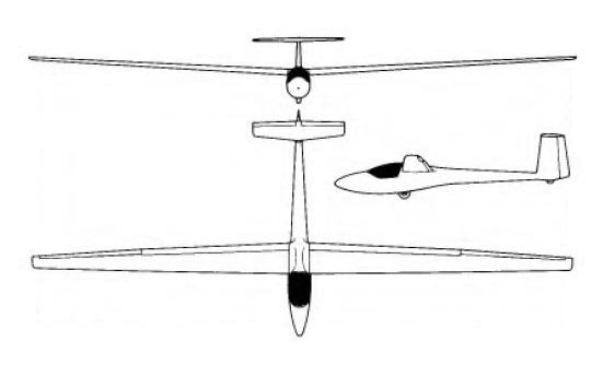
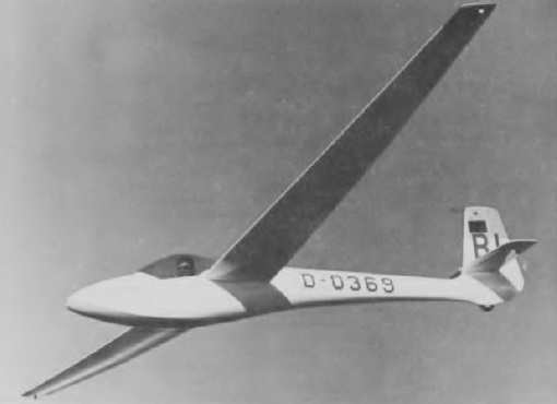
Regarded as having one of the highest performances of any sailplane when it was first rolled out at the end of 1962, the BS 1 had a prone position for the pilot to keep the fuselage cross section as small as possible, as well as a braking parachute housed in the T-tail.
It was designed by Bjorn Stender, who had worked on the SB-6 when a student at Akaflieg Braunschweig and who in 1962 had been asked to design and build a high performance sailplane by the South African pilot and industrialist Helli Lasch. He set to work with only three other helpers and in spite of the BS 1’s advanced nature they succeeded in finishing it by the end of 1962; it was of glassfibre construction – still a comparative novelty at that time – and also had camber changing flaps. The BS-1 has airbrakes, retractable wheel and a tail chute.
After completing its flight tests the BS 1 broke the 300km (186 mile) international triangular speed record during the spring of 1963 and also had a number of competition successes. The BS-1 won the world 300 km speed record (135.3 kph / 85.94 mph) set by Alfred Rohm of West Germany in 1967. In 1970 Terry Thys of San Leandero, Ca made a 917 km / 570 mile flight; which was then the third longest in soaring history.
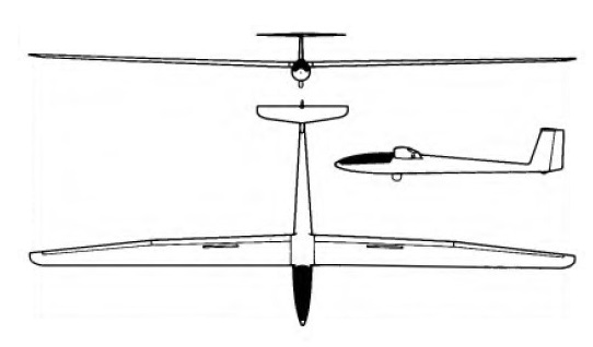
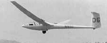
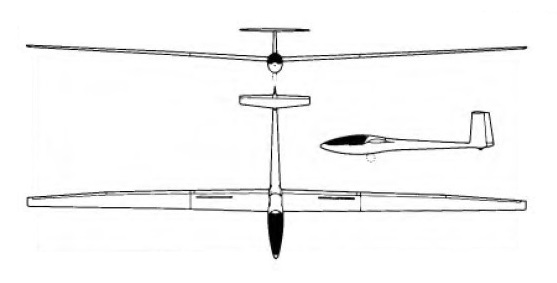
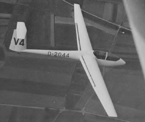
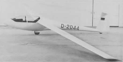
But following the death of Bjorn Stender on a test flight in October 1963 the type was taken over by the Glasflugel company, who produced the modified BS 1B, which first flew on 24 May 1966. This featured a redesigned fuselage to provide a roomier cockpit, and a modified wing of increased span and a new Eppler 348 aerofoil section to give improved soaring capabilities in weak thermals. Glasflugel built a total of 18 BS 1Bs, one of these being supplied to the naturalist and sailplane pilot Sir Peter Scott.
BS 1B Wing span: 18m / 59ft Aspect ratio: 23 Wing area: 14.1 sq.m / 151.7 sq.ft Wing section: Eppler 348 Length: 7.5 m / 24 ft 7.5 in Height: 1.54 m / 5 ft 0.5 in Empty Weight: 335 kg / 739 lb Payload: 125 kg / 275 lb Gross Weight: 460 kg / 1014 lb Water ballast: None Wing Load: 32.62 kg/sq.m / 6.68 lb/sq.ft Max speed: 155 mph / 135 kt / 250 km/h Stalling speed: 35 kt / 65 km/h Max rough air speed: 135 kt / 250 km/h L/DMax: 44 at 95 kph / 51 kt / 59 mph MinSink: 0.54 m/s / 1.78 fps / 1.05 kt at 53 mph / 46 kt / 85 km/h Water Ballast: 0kg / 0lb Seats: 1 No. Built: 18
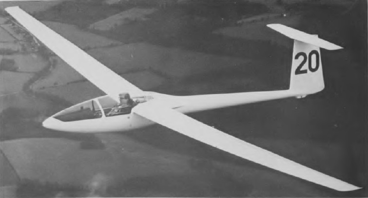
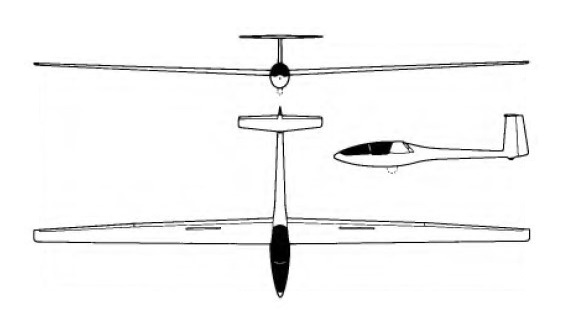
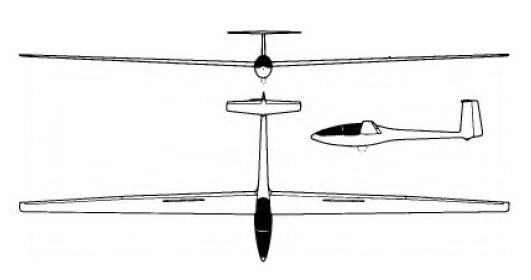
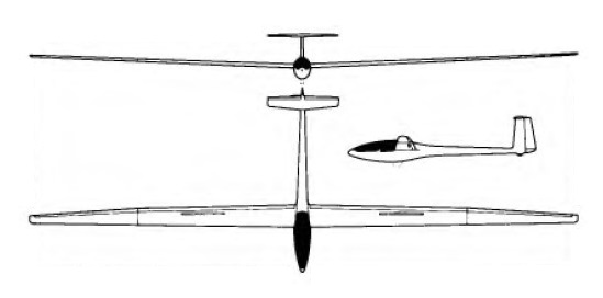
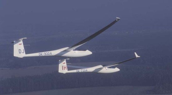
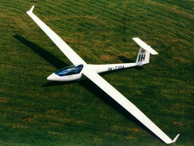
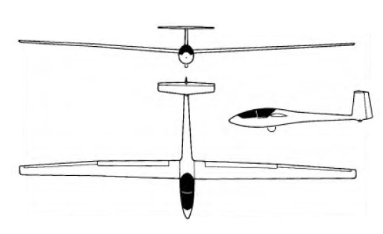
The 604 high performance single-seater by Hanle and Prosser is a 22m span version of the Kestrel 17, and in fact originated as a design study for a similar two-seater sailplane.
Originally intended as a development vehicle for a two-seat high performance sailplane, the 604 has a three-piece wing weighting more than 272 kg/ 600 lb.; just the center section weights 160 kg/ 353 lb. The wing has six flaps, the outer pair of which move at a 2:1 differential with the ailerons. Large spoilers deploy from the upper wing surface only, and there is a tail chute for added approach control.
The 604’s wing consists of a centre section incorporating the fuselage top, and two outer panels joined to the centre section by the Hutter-Hanle method. The fuselage is 5ft 5in longer than the Kestrel 17’s to give improved directional control with the longer span wing; the cockpit canopy, which is slightly shorter than the Kestrel’s, is hinged to open upward and aft. There is a manuallly retractable monowheel with a brake, and a fixed tailwheel. Structurally the 604 is very similar to the Kestrel 17, and can carry up to 220lb of water ballast.
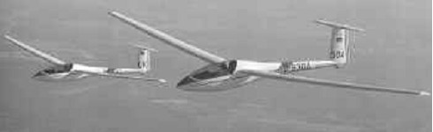
The prototype made its first flight in April 1970, only four months after construction began, and took part in the 1970 World Gliding Championships at Marfa, Texas, taking sixth place; it later took second place in the 1974 World Championships at Waikerie, Australia.
Only 10 604s were built but the type gained a number of competition successes and has set several world and national records, including one for speed over a 300km triangle, set by W. Neubert of West Germany in Kenya in March 1972 with a speed of 95.3mph, and the ladies’ 100km triangular speed record of 79.1mph set by Adele Orsi of Italy in August 1975.
Wing span: 22m / 72 ft 2 in Wing area: 16.26 sq.m / 174.7 sq.ft Length: 7.6 m / 24 ft 11.25 in Height: 1.67 m / 5 ft 5.75 in Empty Weight: 420 kg / 926lb Payload: 180 kg / 397 lb Gross Weight: 600 kg / 1230 lb Wing Load: 36.9 kg/sq.m / 7.57 lb/sq.ft Water Ballast: 0 kg / 0 lb Max speed: 135 kt / 250 km/h / 155mph (smooth air) Stalling speed: 34.5 kt / 64 km/h L/DMax: 49 at 98 kph / 53 kt / 61 mph MinSink: 0.50 m/s / 1.64 fps / 0.97 kt at 45mph / 39 kt / 72 km/h Aspect ratio: 29.8 Airfoil: Wortmann FX-67-K-170/150 Seats 1 No. Built 10
Designed by Hanle and Prasser, the 17m Kestrel high performance Open Class single-seater was designed to meet the demand for a successor to the Libelle variants with a longer wing span and roomier cockpit; it was known originally as the 17m Libelle and has a new fuselage and wing profile and a T-tail. The fuselage is a fiberglass monocoque (not sandwich) for greater resilience and pilot protection. The cockpit has room enough for a 198 cm / 6 ft pilot and features a control stick that slides fore and aft (rather than rotating) to reduce likelihood of pilot induced oscillations and which has a press-to- trim-push-button trimmer. It has a nose and a center of gravity release.
The cantilever two piece shoulder wings are of glassfibre and balsa and/or foam sandwich construction, with unidirectional glassfibre spar caps and glassfibre and balsa shear webs. To cure a small airflow separation problem at the wing root fuselage junction at low speeds large wing root fillets were added to production aircraft; these were actually developed by Vickers-Slingsby, who built the Kestrel 17 under licence. High lift camber-changing flaps are featured which operate in conjunction with the ailerons between 8° and +12°, and can be lowered to 35° for a landing; both ailerons and flaps are partially mass-balanced. It features airbrakes, drogue chute, water ballast and retractable gear. Up to 99lb of water ballast can be carried. There are flush fitting air brakes on the wing upper surfaces, and also a tail braking parachute which can be streamed for short-field landings.
The Kestrel 17 tail unit is similar in construction to the wings, the fixed T-tail being secured by three attachments. Both the elevator and rudder are mass balanced. The monowheel is retractable, with an internally expanding brake, and there is an interchangable tailwheel or tailskid.
The prototype Kestrel first flew at Karlsruhe-Forchheim on 9 August 1968 and production deliveries began the following year, reaching a total of 129 by January 1978.
Kestrel 17m
The Kestrel 17 has several records to its credit. Goran Ax won the second Smirnoff Transcontinental Sailplane Race in a Kestrel in 1973. Sue Martin of Australia gained both the womens world 100 km speed record (113.2 kph / 70.36 mph ) and 300 km triangle speed record (114.4 kph/ 71.11 mph). The 100km closed circuit speed record of 102.74mph was set by K. B.Briegleb of the USA on 18 July 1974 (since broken by an AS-W 17), and the ladies’ 300km closed circuit speed record of 71.1mph set up by Susan Martin of Australia on 11 February 1972.
Glasflugel 401 Kestral 17
The Italian firm of Glasfaser Italiana SrL has also built 25 Kestrel 17s, as well as 130 complete fuselage assemblies for the Kestrel.
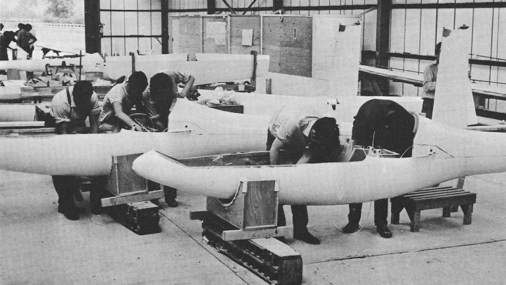
After Slingsby Aircraft Company Ltd had gone into liquidation in July 1969 the firm was reorganised as part of the Vickers Group, at first as Slingsby Sailplanes, later trading as Vickers-Slingsby and then as Slingsby Engineering Ltd. It was decided in September 1969 to produce a modern glassfibre design, and a licence to build the Kestrel was negotiated with Glasflugel. Construction of the first Slingsby-built T 59 Kestrel 17 began in March 1970, and it first flew on 15 August that year at Rufforth, Yorkshire.
Slingsby Glasflugel Kestrel
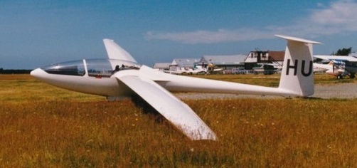
After putting the Glasflugel Kestrel 17 into production, Vickers-Slingsby (later Slingsby Engineering Ltd) began to pursue its own line of development of this Open Class single-seater, which resulted in the 19m span T59B, T59C and T59D. The first 19m span Kestrel, the T 59B, being flown by Mr G Burton in the 1970 World Championships in Texas. The 19m T 59C, which had a carbon-fibre main spar, first flew on 7 May 1971. This was followed by the T 59D of the same span, which first flew in July 1971, the extra span being in the form of 0.5m at each wing root and 0.5m at each wing tip. The T 59D also featured a larger fabric-covered rudder and an antibalance tab in the elevator.
Slingsby T59D ZK-GHU
The D model was still further developed into the T59H of 22m (72ft 2.25in) span, the extra span consisting of two 1.5m stub wings inserted into the exisiting wing at the roots. The fuselage is similar to the Kestrel 17 up to just aft of the canopy, beyond which an additional section 29 1/2 in long is inserted which considerably reduced the ‘waisting’ of the earlier version. The fin and rudder area are increased by about 25%, although the tailplane is the same size as the Kestrel 17’s; the rudder is lightened to prevent flutter by fabric-covered cut-out sections.
The T.59H Kestrel 22 is a special version of the single-seat high performance Kestrel 19 and the prototype was built by using a Kestrel 19 with two 1.5 metre stub wings, complete with flaps, inserted at the wing roots and an extra fin extension mounted above the tailplane. The idea was to make these modifications available to any owner of the Kestrel 19 who wanted to increase the performance of his sailplane.
Two prototype T59Hs were built, the first of these flying in 1974, but the new variant was found to suffer from a wing flutter at 140kts (161mph); Vickers-Slingsby had to recover the prototype T59H from the original customer who had bought it, while the flutter problem was investigated by the College of Aeronautics, where it was still being studied early in 1978.
T.59H Kestrel 22
Like the T59C, the H has a carbon-fibre main spar and, apart from the longer fuselage and long-span four-piece wing, joined at the flap/aileron junction, incorporate carbon-fibre spars and large Schempp-Hirth airbrakes on both upper and lower surfaces, it is structurally similar to the Kestrel 17 with the same cantilever T-tail, up to 220lb of water ballast can be carried. There are Schempp-Hirth air brakes in the upper and lower wing surfaces, and there is a monowheel. The two T59H prototypes are known as the Kestrel 22 Series 1 and Series 2.
The fuselage has been lengthened by 750 mm (2 ft 4½ in) by adding a section to the 19m Kestrel just aft of the wing trailing edge. The tail unit is like that of the Kestrel 19 with the weight of the rudder reduced to prevent flutter by cutting panels out of the glassfibre skin and covering with fabric. Landing gear comprises a large retractable unsprung Gerdes monowheel with a disc brake, plus a fixed tailwheel. The disc brake is operated by a hydraulic unit coupled to the airbrake system.
The T59H was abandoned in favour of a new aircraft, the Kestrel 22.
A total of 101 Kestrels had been built by Vickers-Slingsby by the end of 1974, plus two 22m span T 59H Kestrel 22s. Most of these have been 17m span versions.
Slingsby T-59H Span: 22.0 m / 72 ft 2.25 in Length: 7.55 m / 24 ft 9.25 in Height: 1.94 m / 6 ft 4.25 in Wing area: 15.44 sq.m / 166.2 sq.ft Aspect ratio: 31.35 Wing section: Wortmann FX-67-K-170/150 Empty weight: 390 kg / 860 lb Max weight: 659 kg / 1,453 lb Water ballast: 100 kg / 220 lb Max wing loading: 42.68 kg/sq.m / 8.74 lb/sq.ft Max speed: 155 mph / 110 kt / 204 km/h (in smooth air) Max aero-tow speed: 93 mph / 105 kt / 194.6 km/h Min sinking speed: 0.48m/sec / 1.57 ft/sec at 53 mph / 46 kt / 85 km/h Best glide ratio: 51.5:1 at 64.5 mph / 56 kt / 104 km/h
Intended to succeed the Mosquito B, the 15m span Glasfliigel 304 single-seater is a new design very similar to the Mosquito, work on which began in the autumn of 1979 by a team under Martin Hansen.
Construction is of glassfibre, with no carbon-fibre employed, although the 304/17 (now known as the Glasflugel 402), which has detachable wing tips to give a span of 17m, has largely carbon-fibre wing tips. It employs a new 16.4% thickness/chord ratio wing profile developed by Akaflieg Braunschweig and extensively tested and refined on a Mosquito. It features Glasflugel trailing edge dice brakes and interconnected variable camber flaps, a parrallogram control stick, T-tail with fixed stabilizer and elevator, and automatic connection on assembly of all flight control. The fuselage is similar to the Mosquito’s but with a more pointed nose; the monowheel is retractable. The instrument panel can be tipped up, together with the front-hinged upwards opening canopy, with which it is integral, to allow the pilot more unobstructed entry. Up to 253lb of water ballast can be carried.
The prototype, D-9304, first flew on 10 May 1980. Production of the 304 started in the spring of 1981.
Glasflugel 304 CZ
HPH Ltd. took over the original molds and drawings for glider Glasflugel 304 from Mr. George Brauchle in 1998.
402 Span: 55 ft 9.25 in Length: 21 ft 2in Height: 4 ft 5.5 in Wing area: 114 sq ft Aspect ratio: 27.3 Empty weight: 518lb Max take-off weight: 992lb Max speed: 156mph (smooth air) Min sinking speed: 2.26ft/sec at 58mph Best glide ratio: 43:1 at 72mph
Designed by Eugen Hanle for the 15 m racing class, the Mosquito is a development of the Club Libelle and differs from the earlier Hornet chiefly in having carbon-fibre mass-balanced ailerons, and a new flap/spoiler/air brake system.
Design of the Mosquito was started in the summer of 1975 and the Mosquito’s construction is generally similar to the Hornet, except for the ailerons, and up to 253lb of water ballast can be carried. The structure is fiberglass, with CFRP wing box spar and skin. The new flap/air brake system was developed jointly by Klaus Holighaus and Eugen Ha’nle; conventional camber-changing trailing edge flaps act in conjunction with spoilers immediately ahead of them in the wing upper surface to act as a trailing edge air brake. The normal flap lever lowers the flaps and droops the ailerons in conjunction with them, while there is a second lever for the spoilers or brake flaps. As this is pulled, the spoilers start to open and further backward movement movement of this lever moves the flaps further downwards as well as opening the spoilers further. The latter can be opened or closed at any time like the more conventional Schempp-Hirth type air brakes fitted to other sailplanes. The tailplane at the top of the fin is fixed incidence, and the elevator has spring trim. The retractable unsprung monowheel has an internally expanding brake, and there is a fixed semi-recessed tailwheel. The one-piece canopy is raised by the pilot to hinge forward onto the nose tip for exit.
The prototype first flew in March 1976, it was the first type to go into production after the reorganisation of the Glasflűgel company under the name Holighaus & Hillenbrand GmbH & Co K.G following the death of its Director, Ing Eugen Ha’nle, on 21 September 1975. Dipl-lng Klaus Holighaus, the Director of Schempp-Hirth and Herr Hillenbrand of Glasflűgel formed the present company, continuing to market them under the Glasflűgel name.
A total of 90 Mosquitos had been delivered by January 1978.
Glasflűgel began building the prototype of a new version, the Mosquito B, in September 1977. This differs from the standard Mosquito in having glassfibre reinforced plastic ailerons, no fuselage/wing root fairings, a reduced wing span and a tailplane of reduced span. Empty weight is reduced to 518lb but maximum weight and performance are the same as the standard Mosquito. First flight was on 24 March 1978 and about 90 Mosquito Bs had been delivered by January 1980.
Mr Humphrey Dimock, who runs the Royal Naval Gliding Club at Lee-on-Solent in Hampshire, has fitted a Mosquito with a 36-cell solar panel in the cockpit to charge a German Dry-Fit 14 volt battery at a rate of 0.46A when in sunlight; spare capacity generated by the panel can power blind flying instruments if necessary and there is a cut-out to prevent overcharging. The panel weighs only a few ounces and is mounted directly in front of the pilot edge-on to his line of sight so as not to restrict visibility. Following the success of this panel Mr Dimock planned to fit 10 solar cells in a 5ft x 3.5in strip along the top of the fuselage under a Perspex fairing.
In 1954 Eugen Hänle was then Assistant Professor Ulrich Hütter in a company engaged in the manufacture of large wind turbines for electricity production. The design of the 17 meter blades used fiber reinforced plastic glass.
With this experience, Eugen Hänle established Glasflügel in 1957, to produce helicopter rotor blades for Bölkow.
Meanwhile, Hütter had developed the H-30TS glider, derived from the H-30, with a modified fuselage to accommodate a small BMW turbojet and a new wing of 15 m with plastic flaps, but with glued aluminum sheet metal spar. Hänle then used the molds to produce wings in the Schempp-Hirth workshop. Two sets of wings with glass fiber spar were made. One of the wings was the first H-301 Libelle (or Dragonfly), other than the first Swiss Diamond, with its original 15 m wingspan.
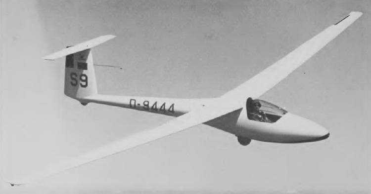
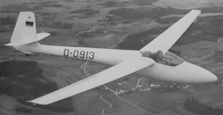
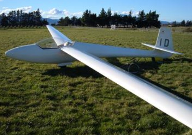
Designed by Wolfgang Hutter and Eugen Hanle, the Libelle first flew on 6 March 1964 and became the first fiberglass sailplane to receive an U.S. ATC. Although of Standard Class span, its camber-changing flaps and manually retractable monowheel put it into the Open Class; it could, however, be flown with flaps up and wheel locked down to conform with the then Standard Class rules. The two-piece cantilever mid wings are glass-reinforced plastic/balsa sandwich structure with a single spar web and no ribs; the glassfibre spars are joined at the fuselage by a tongue/fork type of junction which was later to be adapted in a number of other sailplane designs. The mass-balanced ailerons are linked differentially with the flaps, and there are Hütter air brakes, each 8 ft 2.5 in long, forward of the flaps. The wing leading edge has a compartment for water ballast, of which 110 lb can be carried.
The fuselage is an all-glassfibre monocoque with balsa and synthetic foam and an integral fin; and the rest of the tail unit is of the same type of construction as the wings. The pilot sits in a semi-reclining position under a rearward-sliding one-piece canopy to reduce fuselage cross-section and hence drag, and a slightly higher canopy could be fitted if the customer so desired; there is provision for radio and oxygen, and the seat backrest and rudder pedals are adjustable in flight. The monowheel is mounted on a glassfibre shock absorber and has a brake; it is supplemented by a sprung tailskid or tailwheel.
In 1969 Soaring magazine readers voted the Libelle the World’s most beautiful sailplane. The H 301 Libelle has camber-changing flaps and was able to compete both in the Open Class and, with locked flaps, in the Standard Class.
A total of 111 Libelles had been built when production finally ceased in 1969.
Libelle 301 Wing span: 15 m / 49.2 ft Wing area: 9.5 sq.m / 102.25 sq.ft Aspect ratio: 23.6 Wing section: Hutter Length: 6.2 m / 20 ft 4 in Height: 2 ft 7.8 in (wheel up) Empty Weight: 180 kg / 397 lb Gross Weight: 300 kg / 661 lb Payload: 120 kg / 264 lb Water ballast: 50 kg / 110 lb Max speed (smooth air): 155 mph / 135 kt / 250 km/h Stalling speed: 35 kt / 65 km/h Max aero-tow speed: 84 mph Max rough air speed: 86.5 kt / 160 km/h Wing Load: 31.25 kg/sq.m / 6.4 lb/sq.ft L/DMax: 39 at 95 kph / 51 kt / 59 mph MinSink: 0.55 m/s / 1.8 fps / 1.07 kt at 46.5mph / 40.5 kt / 75 km/h Seats: 1
Designed by Eugene Hanle as a successor to the H 201 Standard Libelle, the Hornet is a derivative of the Club Libelle, differing from it chiefly in having an enlarged, longer two-piece flush-fitting cockpit canopy hinged at the front and rear, a retractable instead of fixed monowheel, and provision for up to 165lb of water ballast.
This Standard Class mid-wing design has a T-tail and the entire structure is of glassfibre monocoque, glassfibre/foam sandwich and glassfibre/balsa sandwich. The mid wing has a different incidence to improve high speed performance. Rotating air brake-type flaps and partially mass-balanced ailerons are on the wing trailing edges, and the elevator has a spring trim. The Hornet has trailing edge dive brakes operating well behind the laminar lift- producing area of the upper wing. The structure is fiberglass with a carbon wing box spar and skin, and Kevlar reinforced cockpit.
The unsprung monowheel has an internally expanding brake, and there is a fixed tailwheel.
The prototype made its first flight on 21 December 1974 and a total of 90 Hornets had been delivered by the summer of 1979.
The Hornet C introduced in 1979 has a carbon-fibre torsion box to each wing, with carbon-fibre spar caps and a wing skin of carbon-fibre/plastic foam sandwich; the lighter weight of these wings allows the water ballast capacity to be increased to 375 lb (an additional 30 kg / 66 lb). The wing root fairings are modified and the C has the same one-piece cockpit canopy as the Glasflugel Mosquito. The prototype Hornet C first flew on 6 April 1979.
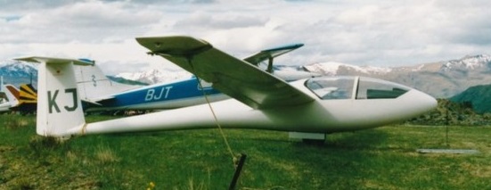
Glasflugel H-206 Hornet ZK-GKJ
Hornet Wing span: 15.0 m / 49 ft 2.5 in Length: 6.4 m / 21 ft 0 in Height: 1.4 m / 4ft 7 in Wing area: 9.80 sq.m / 105.5 sq ft Wing section: Wortmann FX-67-K-150 Aspect ratio: 23.0 Empty weight: 227 kg / 500 lb Max weight: 420 kg / 926 lb Water ballast: 120 kg / 265 lb Max wing loading: 42.9 kg/sq.m / 8.8 lb/sq ft Max speed: 135 kt / 250 km/h Stalling speed: 36 kt / 67 km/h Min sinking speed: 0.60 m/sec / 1.97 ft/sec at 40.5 kt / 75 km/h Best glide ratio: 38 at 56 kt / 103 km/h
Wing span: 15 m / 49.2 ft Wing area: 9.8 sq.m / 105.5 sq.ft Aspect ratio: 23 Airfoil: Wortmann FX 66-17 Length: 21 ft 0 in Height: 4 ft 7 in Empty Weight: 227 kg / 500 lb Payload: 193 kg / 426 lb Gross Weight: 420 kg / 926 lb Wing Load: 42.86 kg/sq.m / 8.8 lb/sq.ft Water Ballast: 170 kg / 375 lb Max speed: 155 mph Max aero-tow speed: 93 mph L/DMax: 38 103 kph / 56 kt / 64 mph Best glide ratio: 38:1 at 47mph MinSink: 0.60 m/s / 1.96 fps / 1.16 kt at 47mph Seats: 1 No. Built: 102
The Libelle and Standard Libelle had proved to be so popular that the need was recognised for a development of these designs suitable for club training, especially for conversion training to the modern high performance glassfibre types in both Standard and Open Classes, and also for advanced cross-country soaring in preparation for Diamond C flights. Good handling characteristics and ease of landing away from base for the less experienced pilot were also necessary, and these were the qualities Eugen Hanle sought in the Club Libelle.
This was based on the Standard Libelle, differing from it principally in having new double-taper shoulder-mounted wings with a double taper, and a T-tail. The two-piece wings are of glassfibre reinforced plastic (GRP) foam section with spar flanges of parallel glassfibre and spar webs of GRP-balsa. The wings carry broad-span trailing edge flaps for approach control.
The fuselage is an all glassfibre monocoque with no balsa or other type of sandwich, and there is a fixed monowheel with a brake. The cockpit is roomier than the Standard Libelle’s, although the one-piece canopy is shorter, and the Club model does not carry water ballast.
The prototype Club Libelle made its first flight in September 1973 and a total of 171 had been built when production ended in August 1976.
Designed by Wolfgang Hűtter and Eugen Hanle, the Standard Libelle is a version of the Open Class H 301 Libelle with modifications to meet the Standard Class requirements; these consisted of removing the flaps and tail braking parachute, fitting a fixed instead of retractable monowheel and raising the height of the canopy. A new Wortmann wing section is featured and terminal velocity dive brakes are fitted. The canopy has a catch that enables the front to be raised by 25mm in flight to provide a blast of ventilating air if required, instead of the more conventional small sliding panel. The Standard Libelle is of similar glassfibre construction to the H 301 Libelle, and likewise has provision for 110 lb of water ballast in the wing leading edge.
The H 201 Standard Class version prototype first flew in October 1967. It originally had a fixed landing gear; but with a change in the Standard Class rules, a retractable gear (H 201B) became standard. The B model features larger upper surface dive brakes, a larger stabilizer for better low-speed handling, PVC foam filler for the wing ( instead of balsa) to increase durability and profile accuracy, and (as an option) a water ballast system (50 kg. /100 lb.) with lighter gross weight.
Glasflugel H201 Standard Libelle
A total of 601 being built.
One flown by Per-Axel Persson of Sweden, winner of the 1948 World Championships, came second in the Standard Class at the 1968 World Championships at Leszno in Poland. In 1970 Sue Martin of Australia set a womens world Out & Return record with a flight of 656 km / 407.64.
H 201B Span: 49 ft 2.5 in / 15.0 m Length: 20 ft 4 in / 6.2 m Height: 4 ft 4 in / 1.31 m Wing area: 105.5 sq ft / 9.8 sq.m Aspect ratio: 23.0 Wing section: Wortmann FX-66-17A-11-182 Empty weight: 408 lb / 185 kg Max weight: 772 lb / 350 kg Water ballast: 110 lb / 50 kg Max wing loading: 7.31 lb/sq.ft / 35.7 kg/sq.m Max speed (smooth air): 155 mph / 135 kt / 250 km/h Max rough air speed: 135 kt / 250 km/h Stalling speed: 33.5 kt / 62 km/h Min sinking speed: 1.96 ft/sec / 0.60 m/sec at 46.5 mph / 40 kt / 75 km/h Best glide ratio: 38:1 at 53 mph / 46 kt / 85 km/h
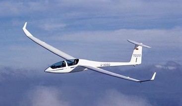
Long term plans for DG Flugzeugbau were to design and construct a a two seater glider, the DG-1000 – and from 2009 on the DG-1001. The Airfoil is a laminar wing section designed by Horstmann/Quast from DLR Braunschweig. The Technical University of Delft completed the design with the addition of winglets and optimizing the wing- fuselage intersection. The wing section is slightly less efficient at best L/D, however much better above 160 km/h. This was combined with very docile stalling characteristics and low bug- and rain sensitivity. The DG-1000 can be flown with 2 wing-spans. For easier rigging each wing features a parting device at about the 17.2 meter point. For flying at the 18 meter span a set of 0.4 meter long wing tips with “miniwinglets” are added (similar to the standard DG-800 18m tips). This configuration is designed to produce good rolling qualities and predictable flight behavior. For cross-country flying the 20m wing tip extensions with integral winglets are added. In addition the four-part trapezoidal wing of the DG-1000 has a small advantage over a two-part trapezoidal plan form at low speeds. The wings of the DG-1000 wing are about 89 kg. The fuselage incorporates a high seating position of the rear seat and a two-piece canopy. The landing gear has a shock-absorbing, new mechanism providing high comfort. One wheel extends forward from the landing gear compartment beyond the centre of gravity. The DG-1000 therefore tends to sit up, even with a pilot in the front cockpit. The sudden pitch up on winch launch is avoided because the glider always rests on the tail wheel. The big spring gives comfort during taxiing and the wheel comes with a hydraulic disk brake. The higher weight for the tail wheel is easy to handle with a towing device made by COBRA-Trailer. The sailplane has been designed with new profile sections and optimized to the size of the wings. There is a compartment in the vertical fin for ballast weights which is accessible via a removable panel. The wing-fuselage intersection was optimized for optima lboundary layer conditions with special airfoils in this area. Winglets are standard for the 20m span which performance-wise will result in a wingspan of approx. 21 meters. The drag of the nose wheel has been eliminated. From the beginning the DG-1000 was planed with an engine – as a self-launcher or as a Turbo-version. The maiden flight did not occur until July 28th, 2000.
The DG-1001S is the standard model with a 20 m span, winglets, retractable main gear, trim box, and water ballast. Additional there is an option for the landing gear of the DG-505 Orion.
DG-1001S-18/20 For this variation wing tips for an 18 m wingspan are available. 1.4 meter extensions, including winglets are available as options. In this version the DG-1000 is a very good aerobatic trainer. The extensions transform the ship into a high-performance cross-country machine.
DG-1001S Club A less expensive entry model, the span is fixed at 18 m, the gear is non retractable, and there is no water ballast system. The Club Model can be ordered with “normal” retractable gear, water ballast system, and with removable tips. This gives the option of later adding the wing extensions, including winglets thus giving a complete DG-1001S-18/20m.
DG-1001T The motorized version as a Turbo with a wing span of 18 or 20 m was available since spring 2005. The DG-1000, with the help of the trim box and fin tank, can be set up with a suitably rearward C.G. for spin training.
DG-1001M The motorized version as a Self Launcher with a wing span of 20 m was available since autumn 2009.