Grumman-American GA-7 Cougar / Socata TB320 Tangara / Socata TB360 Tangara

Grumman GA-7

Right on schedule, in December 1974, Grum¬man American got its new light twin, the Cougar, into the air on its first test flight.

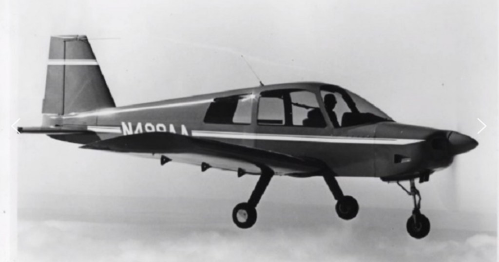
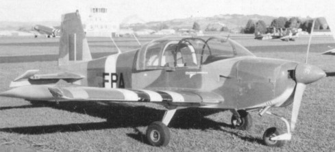
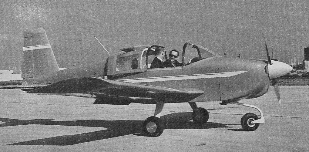
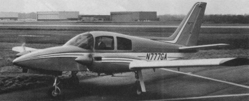
The Cougar had a lengthy development period – nearly three years – between the prototype’s first flight on December 20 1974 and certification in September 1877. During that time the aircraft was modified considerably in detail. First flown with a sliding canopy and two cabin windows per side. A third window had been added by the time the aircraft entered production and the sliding canopy replaced by a conventional solid cabin roof and starboard side entry door.

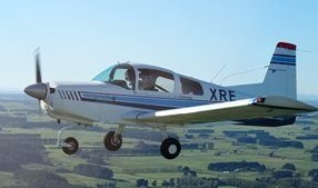
The cabin itself was made a little larger while a two spar wing helped form the structure for an integral wet wing fuel tank. On the prototype the main undercarriage units retracted inwards but on the production models they retracted outwards. The first production standard Cougar flew in January 1977.

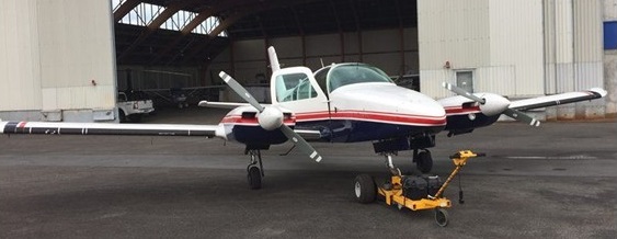
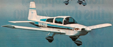
Two models were offered for the 1978 model year, the basic GA-7 and the better equipped Cougar with improved fittings, a basic avionics pack and gyro system as standard.

In service, the Cougar’s single engine performance on only 160 hp / 119 kW a side proved to be not as great as early published figures indicated and the numbers were subsequently revised downwards by nearly 30%.
Gulfstream responded by proposing two new variants, one with turbocharged 160 hp / 119 kW engines and another with 180 hp / 134 kW normally aspirated engines.

Neither proposal eventuated as Gulfstream ended production of all light aircraft in 1979.

In 1995 plans were made for SOCATA to licence build the Grumman GA-7 Cougar as the TB320 Tangara.

SOCATA TB 360 Tangara

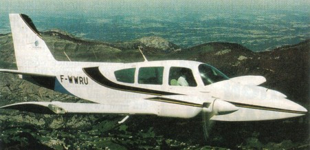
Socata acquired the design and manufacturing rights to the Cougar in 1995. Socata announced plans to produce the aircraft as the TB 320 Tangara and then as the TB 360 with 180 hp / 134 kW Lycoming O-360 engines.
Three modified Cougars were built as prototypes, the first (as a TB 320) in mid 1996 and the second (as a TB 360) in February 1997. Planned production was then delayed.
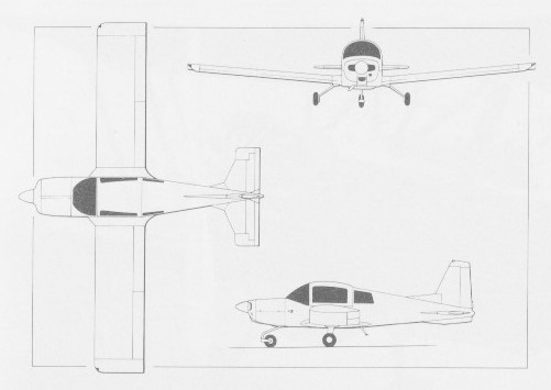
Grumman GA-7 Cougar
Engines: Lycoming 0 320 D1D, 160 hp / 119 kW
TBO: 2,000 hrs.
Props: two blade, constant speed, 73 inch dia.
Length: 29 ft. 10 in.
Height: 10 ft. 4 in.
Wingspan: 36 ft. 10 in.
Wing area: 184 sq.ft.
Wing loading: 20.67 lb/sq.ft.
Power loading: 11.88 lb/hp.
Seats: 4.
Empty weight: 2,569 lb (1,165 kg)
Useful load: 1,155 lbs.
Payload with full fuel: 459 lbs.
Gross weight: 3,800 lb (1,724 kg)
Usable fuel capacity: 116 USG/696 lbs.
Service ceiling: 17,400 ft (5,300 m)
Rate of climb: 1,150 ft/min (5.8 m/s)Single engine rate of climb: 280 fpm.
Single engine climb gradient at 85 knots (Vyse): 197 ft. per nm.
Single engine service ceiling: 4,500 ft.
Maximum speed: 117 kts.
Max cruise, 75% power (2,700 rpm) at 8,500 ft: 165 kts.
Range: 1,170 nmi (max econ no res)
Duration at maximum cruise: 6.7 hrs.
Duration at economy cruise: 9.2 hrs.
Stalling speed, clean: 68 kts.
Stalling speed, full flaps: 61 kts.

Socata TB 360 Tangara
Engines: 2 x Lycoming O-360-A1G6, 180 hp / 134 kW
Wing span: 36 ft 11 in / 11.24 m
Length: 29 ft 10 in / 9.09 m
Height; 10 ft 4 in / 3.15 m
Wing area: 184 sq.ft / 17.1 sq.m
MTOW: 3800 lb / 1724 kg
Max speed: 174 kt / 322 kph
Max cruise; 165 kt / 306 kph
Long range cruise: 120 kt / 222 kph
Initial ROC: 1400 fpm / 427 m/min
Service ceiling; 20,000 ft / 6096 m
Range at max cruise (45 min res): 800 nm / 1480 kg
Max range w/res: 1140 nm / 2110 km

Grumman-American AA-5 Cheetah / Tiger / Traveller

AA-5B Tiger

The production 4-seaters were the AA-5 Traveller introduced in 1971, the AA-5A Cheetah and AA-5B Tiger.
First introduced in 1972 as the AA-5 Traveler, with 150 horsepower, this four-seater resembled an enlarged AA-1 and also utilised the bonded metal and tubular spar construction of the AA-1. In 1975 Grumman American introduced a major airframe clean up and the more powerful 180 hp AA-5B Tiger. The Tiger features an enlarged and redesigned tailplane (from the AA-5), fixed pitch prop and undercarriage. The modified airframe was reunited with 150 hp in 1976, and the new AA-5A Cheetah replaced the Traveler.
All these airplanes share key features. Entrance is through a sliding canopy, which can be left open during flight. Rear seat backs are removable, and the rest of the rear seat folds flat to form a cavernous cargo area, station wagon style. All three airplanes have fixed gear and fixed pitch propellers. And the airframes of the little airplanes are made partially of an aluminum honeycomb material; most of the skins are bonded rather than riveted together.
This skin bonding process has had its troubled moments. Problems occurred when Grumman American moved its light¬plane manufacturing from the Cleveland, Ohio area to Savannah, Georgia. The new plant’s bonding process went through a shakedown period during which, occasionally, an airplane control surface would delaminate. But this never happened suddenly, so there was no safety problem, and the factory made good the airplanes that were affected.
Fuel is drawn from one wing or the other, and a pointer, activated by the selector, indicates which fuel gauge to read.
Taxiing is with the full-swiveling nose wheel dictating that you guide with the toe-brakes.
In addition to their basic clean up modifications, the Tiger and Cheetah also have horizontal and vertical stabilizers that differ from those on the Traveler. The changes offer more balance and more responsive control and eliminate the need for the Traveler’s dorsal fin.
The Grummans share a free castoring nosewheel. Trying to keep the airplane simple, the makers of the Grumman American lightplanes decided to have no steering on the front wheel. Diffeeential braking on the mains swings the nose in the desired direction, and the free turning nosegear follows.

Traveler AA5

For the 1977 model cabin noise is way down from the 1976 model, thanks to a windshield that’s twice as thick and the firewall’s being raised and extended to meet the top of the cowl deck; formerly, there had been a crescent shaped opening that allowed engine noise to pass. The aft skirt of the canopy has a new, redesigned seal, and the forward edge now has two bladder like seals that meet an opposing rubber strip instead of the bare metal of the windshield bow.
Because people had complained about the airplane’s tendency to pitch like a rocking horse on rough surfaces, sometimes leading to prop clings, there’s a new shock absorber for the nosewheel made up of a pair of oleos at the top of the strut, to absorb fore and aft jolts.

Traveler AA5

The rubber seal that covers the attach ¬point gap at the wing roots has been widened. The propeller spinner bulkhead has been beefed up in response to frequent replacements necessitated by cracking. Fuel tank sealing has been im¬proved, as has access to the tanks. Primary airspeed indication is in knots.

The GA Tiger, announced late in 1974, has the same airframe as the Cheetah nee Traveler, but is powered with the Lycoming O-360-A4K of 180-hp, and sold, new, for $5,000 more than the Cheetah. The Tiger has excellent performance, but we’ll deal lightly with it here, because it will be rare in the used market for a while, and priced close to the new ones. The 1976 Tiger’s basic price wasUS$24,170, which may easily go above $30,000 fully equipped.

By 1975, GA was building 200 Travelers per year, along with an equal number of Grumman American Tigers (the 180-hp model) and, following a move from Cleveland to Savannah, programmed for 500 of their four-placers in 1976.
Late in 1975, GA gave the Traveler more stabilizer and flap and rechristened it the “Cheetah”.
The 1976 Cheetah’s basic price is $19,094.

Gallery

AA-5 Traveller
Engine: Lycoming O-320-E2G, 150 hp
Wingspan: 31 ft 6 in / 9.60 m
Length: 22 ft 0 in / 6.71 m
Empty weight: 1200 lb / 544 kg
MTOW: 2200 lb / 998 kg
Max cruise 75% 8500ft/2600m: 122 kt / 140 mph / 225 kph
Max ROC SL: 660 fpm / 201 m/min
Service ceiling: 12,650 ft / 3855 m
Range max cruise 45 min res: 390 nm / 450 mi / 724 km
Cabin length: 6 ft 6 in / 1.98 m
Cabin width: 3 ft 5 in / 1.04 m
Cabin height: 4 ft 0.25 in / 1.23 m
Baggage space: 12 cu.ft / 0.34 cu.m
Baggage space w/rear seat area: 41.5 cu.ft / 1.19 cu.m
Max baggage: 120 lb / 54.4 kg
Seats: 4

AA-5A Cheetah
Engine: Lycoming 0-320-E2G, 150 hp.
TBO: 2,000 hr.
Prop: McCauley fixed pitch, 73 in.
Length: 22 ft.
Height: 8ft.
Wingspan: 31 ft 6 in.
Airfoil: NACA 642415 (mod).
Aspect ratio: 7.1.
Wing area: 140 sq. ft.
Wing loading: 15.7 lbs/sq.ft.
Empty weight: 1,262 lbs.
Useful load: 938 lbs.
Payload with full optional fuel: 626 lbs.
Gross weight: 2,200 lbs.
Power loading: 14.7 lbs/hp.
Fuel cap (standard): 38 USG/1228 lbs.
Fuel cap (opt): 52 USG/1312 lbs.
Baggage cap: 120 lbs.
Seats: 4.
Stall speed (clean): 54 kts.
Stall speed (flaps down): 50 kts.
Minimum runway requirement: 1,600 ft.
ROC: 660fpm.
Service ceiling: 12,650 ft.
Max speed: 137 kts.
Cruise (75% @ 8,500 ft.): 128 kt.
Economy cruise (55% @ 4,500 ft.): 103 kts.
Range @ max cruise (45 min res, std tanks): 461 nm.
Range @ max cruise (45 min res, opt tanks): 672 nm.
Range @ economy cruise (45 min res, std tanks): 537 nm.
Range @ economy cruise (45 min res, opt tanks): 770 nm.
Duration @ max cruise (no res, std tanks): 4.4 hrs.
Endurance 65%: 6.9 hr.
Landing gear: Tri/Fixed
Cabin width: 41 in
Cabin height: 48 in
Takeoff ground roll: 880 ft
Landing ground roll: 380 ft

AA-5B Tiger
Engine: Lycoming 0 360 A4K, 180 hp.
TBO: 2,000 hrs.
Prop: McCauley 75in, fixed pitch.
Length: 22 ft.
Height: 7 ft. 8 in.
Wingspan: 31 ft. 6 in.
Airfoil: NACA642415 mod.
Aspect ratio: 7.1.
Wing area: 140.35 sq.ft.
Wing loading: 17.1 lb/sq.ft.
Seats: 4.
Empty weight: 1,410 lbs.
Useful load: 989 lbs.
Payload with full fuel: 668 lbs.
Gross weight: 2,400 lbs.
Power loading: 13.3 lbs./hp.
Fuel capacity (standard): 51 USG./306 lbs (opt 51 US Gal).
Baggage capacity: 120 lbs.
Baggage area: 15 cu. ft.
Rate of climb: 850 fpm @ 79 kts.
Service ceiling: 13,800 ft.
Maximum speed: 147 knots.
Cruise (75 % @ 8,500 ft): 139 knots.
Economy cruise (55 % @ 8,500 ft): 112 knots.
Range @ max cruise (45 minute reserve): 512 nm.
Range @ economy cruise (45 minute reserve): 567 nm.
Duration @ max cruise (no reserve): 4.5 hrs.
Stall speed (clean): 56 knots.
Stall speed (flaps down): 53 knots.
T/O 50ft: 1550 ft.
Landing dist 50ft: 1120 ft.
Max canopy open speed: 113 kts.
Max X-wind: 11 kts.

Grumman American 1976 AA5B Tiger
Engine: Lycoming O-360-A4K, 180
TBO: 2000 hr
Propeller: Const. spd.
Landing gear: Tri/Fixed
Gross weight: 2400 lb
Empty weight, std: 1294 lb
Useful load, std: 1106 lb
Fuel: 51 USgal
Wingspan: 31 ft. 6 in.
Overall length: 22 ft.
Height: 8 ft.
Wing area:140 sq. ft
Seating capacity: 4
Cabin width: 40 in
Cabin height: 45 in
Baggage capacity:120 lb
Cruise speed 75% power: 139kt
Cruise speed 65% power: 131 kt
Max range (w/ reserve) 75% power: 552 nm
Max range (w/ reserve) 65% power: 578 nm
Fuel consumption 75% power: 10.8 USgph
Fuel consumption 65% power: 9.7 USgph
Stall speed (gear, flaps down) : 53 kt
Best rate of climb: 850 fpm
Service ceiling: 13,850 ft
Takeoff ground roll: 865 ft
Landing ground roll: 410 ft

Traveller

Grumman-American AA-2 Patriot

After the market success of the AA-1 Yankee Clipper American Aviation turned their attention to developing a four-seat aircraft in 1970-71. The American Aviation engineers started with a “clean sheet of paper” and designed a new aircraft. This aircraft was intended to be produced as the American Aviation AA-2 Patriot.

The resulting prototype bore very little family resemblance to the AA-1. The AA-2 was different from the AA-1 in that it had doors instead of the Yankee’s trademark sliding canopy and an oleo strut in place of the Yankee’s spring steel tube nose gear. The aircraft had provisions for retractable gear to be installed on a later version, although the prototype had fixed landing gear. The AA-2 was powered by a 180 hp (134 kW) Lycoming engine.

The prototype, registered “N488AA”, was completed in 1970 and test flying was commenced early in that same year. Aircraft performance during the test flying process fell far short of the design goals so the project was abandoned and the manufacturer eventually disassembled the prototype.

American Aviation made the decision to develop a stretched version of the AA-1 Yankee Clipper instead of pursuing the AA-2. This aircraft eventually was produced as the AA-5 Traveler and was later developed into the AA-5A Cheetah and the AA-5B Tiger.

The prototype has been recovered by members of the American Yankee Association.

Powerplant: 1 × Lycoming O-360-A1A, 180 hp (130 kW)
Wingspan: 30 ft 0 in (9.14 m)
Length: 23 ft 3 in (7.09 m)
Max takeoff weight: 2,400 lb (1,089 kg)
Useful load: 1100 lb
Maximum speed: 135 kn (155 mph, 249 km/h)
Cruise: 145 mph
Range: 613 nmi (705 mi, 1,135 km)
Crew: One
Capacity: Three passengers

Grumman-American AA-1 Trainer / Lynx / T-Cat / Tr-2 / Yankee

AA-1

During 1964, the American Aviation Corporation was formed to bring new life to the promising BD-1 design. The prototype AA-1 Yankee N888M first flew on March 2nd, 1967. The AA-1 was a little larger than the original BD-1 with a more powerful 108hp Lycoming 0-235-C2C engine. It made use of metal-to-metal bonding of components, which was a technique not previously used to and great degree in general aviation aircraft. Also, the construction used a large amount of high-strength aluminium honeycomb material within the fuselage structure and fibreglass in the undercarriage legs.

Grumman-American AA-1 Trainer Article

The AA-1 Yankee introduced a new canopy and Hoerner wingtips which increased the span by 1 ft / 0.2m.

AA-1

This side-by-side trainer first entered production in 1968 as the American Aviation AA-1 Yankee.

The type went into production at Cuyahoga County Airport, Cleveland, Ohio. In all production of the AA-1 Yankee (TC A11EA) totalled 461 units plus the prototype. They were initially priced at $7,295, rising to $7895 in 1971.

The American Yankee was followed by the 1970 American AA-1A Trainer (TC A11EA), which in-corporated a new wing section designed for more docile handling. First flown on 25 March 1970, 680 Trainers were built, priced at $8,340.

The AA-1 Yankee design was progressively developed into the AA-1B Trainer and the AA-1C Lynx.

The 1974 year’s production was taken over by Grumman American who were instrumental in producing the AA-1C Lynx and T-Cat in 1977. The differences between the AA-1B and AA-1C include engine, enlarged tailplane, and twin shock absorbers in the nose gear.

In 1977 Grumman-American were marketing an optional spin package for the AA-1C / T-Cat – basically a ventral fillet or strake under the tail.

The T Cat’s closest sibling, the Lynx, is nearly its twin. The only substantial difference between the two airplanes is the propeller: the former has a 52-in pitch Sensenich climb prop, which provides an extra 50 feet per minute; the latter has a 56-in pitch cruise prop, which offers an additional five knots at cruise.

The Tr-2 is a dual-role advanced trainer / sporting aircraft developed by Grumman American and based on the AA-1B. It did enter production.

Tr-2

Production of the type ceased in December 1978 after 211 Lynx were built.

Gallery

American Aviation AA-1 Yankee
1968
Engine: 108hp Lycoming O-235-C2C
Wingspan: 24’6″
Length: 19’3″
Useful load: 560 lm
Max speed: 144 mph
Cruise: 135 mph
Stall: 65 mph
Range: 500 mi
Ceiling: 11,250′
Seats: 2

1971 Grumman American Trainer AA-1A
Engine: Lycoming O-235, 108 hp
TBO: 2000 hr
Fuel type: 100
Propeller: Fixed
Landing gear: Fixed nose
Max ramp weight: 1500 lb
Gross weight: 1500 lb
Max landing weight: 1500 lb
Empty weight: 1007lb
Useful load: 1007 lb
Payload, full fuel: 349 lb
Usable fuel: 24 USgal
Wingspan: 25 ft 5 in
Overall length: 19 ft. 3 in
Height: 6 ft. 8 in.
Wing area:100.9 sq. ft
Wing loading: 12.6 lbs./sq. ft
Power loading: 15 lb/hp
Wheel track: 8 ft. 3 in.
Seating capacity: 2
Cabin width: 41 in
Cabin height: 45 in
Baggage capacity: 100 lb
Cruise speed 55% power: 100 kt
Max range (w/ reserve) 65% power: 399 nm
Fuel consumption 55% power: 4.2 USgph
Stall speed (flaps up): 55 kt
Stall speed (flaps down): 51 kt
Best rate of climb: 765 fpm
Service ceiling: 13,750 ft
Takeoff ground roll: 700 ft
Landing ground roll: 395 ft

AA-1B Trainer
Engine: Lycoming O-235-C2C, 108 hp
Wingspan: 24 ft 6 in / 7.47 m
Length: 19 ft 3 in / 5.86 m
Empty weight: 980 lb / 445 kg
MTOW: 1560 lb / 708 kg
Max cruise 75% 3000ft/915m: 108 kt / 124 mph / 200 kph
ROC SL: 705 fpm / 215 m/min
Service ceiling: 12,750 ft / 3886 m
Range 75% 3000ft/915m no res: 378 nm / 435 mi / 700 km
Seats: 2
Rear baggage: 100 lb / 45 kg
Cabin length: 4 ft 6 in / 1.37 m
Cabin width: 3 ft 5 in / 1.04 m
Cabin height: 3 ft 9.25 in / 1.15m

AA-1B TR-2 Trainer
Engine: Lycoming O-235-C2C, 108 hp.
Seats: 2.

AA-1C Lynx
Engine: 1 x Lycoming O-235-L2C, 115 hp.
Seats: 2.
Wing loading: 15.9 lb/sq.ft.
Pwr loading: 13.9 lb/hp.
Gross wt: 1600 lb.
Empty wt: 1066 lb.
Equipped useful load: 507 lb.
Payload max fuel: 375 lb.
Range max fuel/75% pwr: 326nm/2.7hr.
Range max fuel / 55% pwr: 350 nm/ 3.7 hr.
Service ceiling: 11,500 ft.
75% cruise: 117 kt.
55% cruise: 96 kt.
Stall: 52-54 kt. 1.3
Vso: 68 kt.
ROC: 700 fpm.
Min field length: 1590 ft.
Fuel cap: 132 lb.

AA-1C T-Cat
Engine: Lycoming O 235 L2C, 115 hp.
TBO: 2,000 hrs.
Prop: Sensenich fixed pitch, 72 inch diameter.
Length: 19 ft. 3 in.
Height: 7 ft. 7 in.
Wingspan: 24 ft. 5 in.
Wing area: 100.9 sq.ft.
Wing loading: 15.85 lb/sq.ft.
Power loading: 13.91 lb/hp.
Seats: 2.
Empty weight: 1,075 lbs.
Useful load: 525 lbs.
Payload with full fuel: 382 lbs.
Gross weight: 1,600 lbs.
Usable fuel capacity: 22 USG/132 lbs.
Maximum landing weight: 1,600 lbs.
Maximum rate of climb: 750 fpm.
Service ceiling: 11,900 ft.
Maximum speed: 125 kts.
Max cruise, 74% power (2,700 rpm) at 5,000 ft: 112 kts.
Econ cruise, 55 % power at 6,000 ft: 93 kts.
Duration at max cruise: 3.4 hrs.
Duration at econ cruise: 4.4 hrs.
Stalling speed, clean 57 kts.
Stalling speed, full flaps: 53 kts.

AA-1

Grumman G-712 / Grumman X-29

Grumman Aerospace, Rockwell International and General Dynamics, proposed to DARPA that a for-ward swept wing demonstrator should be built. The demonstrator would be used to: verify that composites could provide the wing stiffness required without severe weight penalties; verify the aerodynamic advantages of a forward swept wing indicated in wind tunnel testing; and expand the forward swept wing technology base.
DARPA responded favourably and there followed three years of intensive competitive design studies, culminating in Grumman Aerospace being selected to build two demonstrators in 1981 under an $80 million contract, based on their Project Design G 712. This was officially designated X 29A by the U.S. Air Force in mid 1981.
The X-29A was a single-seat jet aircraft fitted with a wing mounted at the rear of the fuselage, swept forward at 35 degrees, and having shoulder-mounted canards just behind the cockpit.
To save development time and money, Grumman used as many parts as practical from existing aircraft. The forward fuselage and nose landing gear are from a Northrop F 5A (the 15th built from the mid-1960s), and the main landing gear and control surface actuators are from a General Dynamics F 16A. Off the–shelf equipment includes the emergency power unit and the flight control servo actuators, also from an F 16A. The aircraft is powered by a single General Electric F404 after burning turbofan, developing 16,000 lb. thrust, and is the engine type used in the McDonnell Douglas F/A 18 Hornet.
The tapered variable incidence foreplane was selected after intensive wind tunnel testing and is used to provide pitch trim and control movements, as this type of surface provides lift for trim. It also acts as a slat to help the heavily loaded inboard section of the wing.
The X 29A is a highly unstable aircraft, the c.g. being no less than 35% aft of the aerodynamic centre of the wing/canard surfaces. Initially the planned instability was intended to be only 20%, and accordingly the canard had an area equal to 15% of the wing. Wind tunnel tests, however, showed that this would not give the degree of control required during transonic manoeuvres, and the canard size was increased to 20% of the wing, giving the current degree of instability.
The heart of the X 29A is its distinctive forward swept wing. It is a very thin wing; the thickness to-chord ratio being less than 5%. The wing area is 188 sq. ft. and the angle of forward sweep 30 deg.

Ultimately, the X-29 emerged with three digital channels so that any two could detect a failure in a third, plus a fourth, analogue backup channel which could control the aircraft over a limited flight envelope. The main role of the fourth channel was to protect the aircraft in case some unsuspected freak software mode disabled all three digital channels simultaneously.

The inboard end of the leading edge is swept aft, to alleviate some of the root stall problems associated with forward sweep. To preserve the structural integrity of the vital lower wing skin, the main landing gear retracts forward, into the fuselage ahead of the wing. The trailing edge of each wing root extends aft to form a large body strake ending in a controllable flap. The strakes add area behind the c.g. and hence improve directional stability.
It is on the outer, forward swept portion of the wing that the unique directional properties of carbon fibre laminates construction are used to overcome the adverse wing twist, or “divergence”, without the prohibitive weight penalty of a conventional aluminium alloy structure. A total of 752 plies is used, with 156 layers at the thickest section of the skin. To resist the natural tendency of the forward swept wing to twist, the layers are “rotated” some 10 deg. forward of the wing’s structural axis.
The laminated wing skins, at an angle to the bending axis, shear forward under compression and back¬ward under tension. The effect of shearing under load on the wing torsion box is to generate a nose down torque which counters the natural tendency of the wing to twist leading edge up. The carbon fibre skins are attached to a sub structure of conventional aluminium alloy construction, the front spar being of electron-beam welded titanium to cater for the high loads on the front part of the wing due to the forward sweep.
Full span “variable camber” flaperons are fitted to the wing trailing edge, these being used symmetrically for pitch control and asymmetrically for roll. The flaperons are in three sections, being hinged at two chord wise locations, so that they may be used to change the camber of the wing. The primary hinge is at 75% chord and the secondary hinge is at 90% of the chord. The flap sections are geared so that for every 1 deg. of flap deflection the aft section deflects an additional 1 deg. The flap increases manoeuvrability and reduces drag across the entire speed range. Programmed by the flight control computer, the flap alters the wing shape in flight as a function of changing conditions. The result is a constantly optimum wing shape.

The core of the wing structure is an electron-beam-welded box of titanium and light alloy, providing an exceptionally sturdy but generally conventional basis for the outer aerodynamic surfaces. The latter are single-piece upper and lower skins made of carbon fibre reinforced plastics up to 156 layers thick at the inboard ends. The skins are exceptionally light yet rigid, and can sustain violent manoeuvres without any possibility of aeroelastic divergence. The leading edges are fixed, with no provision for high-lift devices of any kind, but the trailing edges are fitted with full-span flaperons that can be used as camber-changing sections.
Located aft of the wing are the conventional rudder, plus a pair of strake flaps fitted at the extreme rear of the extended wing root trailing edges, nearly in line with the rudder. Powerful canard foreplanes with one-fifth of the wings’ area are located on the sides of the lateral inlets, and just forward of the inboard sections of the wing leading edge, which are conventionally swept back. The canards are driven through a triple-redundant fly-by-wire flight-control system, and are the aeroplane’s primary control surfaces in the pitching plane. The canards are used to trim out any tail up pitching moment by generating lift, augmenting the lift of the wing.
Flight tests have confirmed wind-tunnel predictions about the X-29’s flight characteristics: even at extreme high angles of attack the aircraft cannot be stalled and it retains full roll authority down to very low speeds. Early flight trials also indicated that fuel burn was lower than expected, an indication of extremely low drag.

The X 29A flew for the first time on 14th December 1984, from NASA’s Dryden Flight Research Facility at Edwards Air Force Base, California, with Grumman chief test pilot Chuck Sewell at the controls. For this first flight, which lasted 57 minutes, the landing gear and the variable camber trailing edge devices were kept down. The gear and flaps were retracted during the second flight on 4th February 1985. Two further flights were made on 25th February and 1st March. Two 360 deg. rolls were made during the third flight. After just these four flights the demonstrator was turned over to NASA in March 1985 for further flight testing.
In the initial phase of testing low altitude, high speed manoeuvres, the X 29 demonstrated high g turns tighter than anything achieved by a conventional fighter and displayed awesome potential for combat aircraft. For an extended test phase, the second aircraft was fitted with a vortex flow control system to test the possibility of using high pressure nitrogen injected directly into the vortices coming off the nose to help maintain control at high AoA. With this, pilots were able to achieve good control response to an AoA of 67 degrees.

The first aircraft (83-0003) flew on 14 December 1984, piloted by Charles Sewell, but was grounded on 6 December 1988 after its 242nd flight. The second X-29A (83-0049), flown for the first time on 23 May 1989, completed its flight test programme in October 1991. Between them the two aircraft completed 374 flights (more than any other X-craft) and demonstrated angles of attack up to 67 degrees (the target was 80). They also flew at Mach numbers up to 1.52 and reached altitudes up to 12200m. Both aircraft were now in store at the Ames-Dryden Flight Research Facility of NASA at Edwards AFB, California.

The X 29 tests ended in 1992 after 436 flights.

Gallery

X 29A
Engine: 1 x General Electric F404 GE 400 after burning turbofan, 69847 N / 16,000 lb. s.t.
Wing span: 27 ft. 2.5 in. / 8.3 m
Length: 16.4 m / 53 ft 10 in
Height: 14 ft. 3.5 in. / 4.4 m
Wing area: 17.5 sq.m / 188.37 sq ft
Foreplane area: 35.96 sq.ft.
Empty wt: 13,800 lb. / 6260.0 kg
MTOW: 17,800 lb. / 8074.0 kg
Max. payload weight : 12819.9 lb / 5814.0 kg
Max speed: Mach 1.6 approx.
Ceiling: 15300 m / 50200 ft
Crew: 1

Grumman WF / E-1 Tracer

Grumman E-1B Tracer

An AEW development of the S-2 Tracker the E-1 Tracer was designated WF under the old US Navy system. The Tracer was fitted with the Hazeltine AN/APS-82 search radar in its radome. The radar featured an Airborne Moving Target Indicator (AMTI), which analyzes the Doppler shift in reflected radar energy to distinguish a flying aircraft against the clutter produced by wave action at the ocean’s surface. Separating a moving object from stationary background is accomplished by suitable hardware.
The E-1 featured folding wings for compact storage aboard aircraft carriers. Unlike the S-2 and C-1 in which the wings folded upwards, the radome atop the fuselage necessitated the E-1 to fold its wings along the sides of the fuselage.

Variants:

XTF-1W/XWF-1
Aerodynamic prototype (BuNo 136792) without electronics, later rebuilt as a standard C-1A, retaining the twin tail.

WF-2
Airborne Early Warning version of the TF-1 Trader, redesignated E-1B in 1962, 88 built.

E-1B
WF-2 redesignated in 1962.

Specifications:

E-1B
Engines: 2 × Wright R-1820-82A Cyclone 9-cylinder radial, 1,525 hp (1,137 kW)
Length: 45 ft 4 in (13.82 m)
Wingspan: 72 ft 4 in (22.05 m)
Height: 16 ft 10 in (5.13 m)
Wing area: 506 sq ft (47.0 sq.m)
Empty weight: 20,638 lb (9,381 kg)
Loaded weight: 24,800 lb (11,273 kg)
Max takeoff weight: 26,600 lb (12,091 kg)
Maximum speed: 207 knots (238 mph, 383 km/h) at 4,000 ft (1,220 ft)
Cruise speed: 142 knots (163 mph, 263 km/h)
Service ceiling: 15,800 ft (4,800 m)
Rate of climb: 1,120 ft/min (5.7 m/s) at sea level
Range: 900 nmi (1,035 mi, 1,666 km)
Endurance: 6.83 hrs (4.63 hrs on station at 150 nm (278 km) at 5,000 ft (1,500 m)
Armament: None
Crew: 4, two pilots, two RADAR/Intercept Controllers

Grumman S-2 Tracker / Turbo Tracker / S2F-1 Sentinel

Grumman S-2E

Grumman’s S 2 Tracker was the first of the US Navy’s post Second World War aircraft to combine the ASW roles of ‘hunter’ and ‘killer’. Prior to its entry into operational service, no one aircraft with adequate perform¬ance and the capability to carry the necessary equipment to seek the sub¬marine, as well as the weapons to destroy it.
The prototype was first flown on 4 December 1952 and S 2A Trackers entered service with the US Navy in 1954. The initial production version was designated S-2A (CP-121, formerly CS2F-1 for the Canadian version).

Grumman S-2 Tracker Article

The mainplanes and tail surfaces are un-swept, with dihedral on the tailplane. Small ailerons are supplemented by long-span spoilers on the top surfaces of the wings. There are fixed leading edge slots on the outer wings and long span slotted trailing edge flaps. The rudder is divided vertically into two parts, the forward part being used only during take-off, landing and single-engine flight. The tricycle undercarriage has twin nose-wheels and single wheel on each main unit. All wheels retract rearward. A partially retractable bumper-wheel is under the rear fuselage, and an arrester hook is under the tail.

CP-121 Tracker 12195 of 880 Sqn RCAF, 1987

In production for the U.S. Navy and in Canada for the Royal Canadian Navy in 1955 as the S2F-1 Sentinel. The S2F-2 is similar, but has a large radar scanner, similar to that carried by AD4W “guppy” Skyraiders, built into the bottom of its fuselage under the cockpit. Both versions combine search and strike duties in a single aircraft. TF-1 trainer is similar. So is transport version, able to carry 8 passengers or over 1,600 lb. cargo for shore-to-ship supply.

Canadian de Havilland built Tracker

The S-2B had new anti-submarine detection equipment, and the TS-2B was a trainer.

The S 2E was powered by two 1,136.4kW / 1,525 hp Wright R 1820 82WA piston engines, and stores which can be deployed include sonobuoys, depth charges, a nuclear depth bomb, bombs, torpedoes, and rockets. The US Navy also operates an AEW version of this aircraft known as the E 1B Tracer.
Other variants include:
S-2G with enlarged bomb bays to house two homing torpedoes (most converted to US-2C or RS-2C)
S-2D with improved anti-submarine equipment, wider cockpit and longer range
S-2F with uprated submarine detection equipment
S-2G, early version uprated with a Martin Marietta kit
US-2A/C, S-2A/C converted for target towing
US-2B utility/transport conversion of the S-2B
RS-2C, S-2C converted for photo-reconnaissance/ survey work
AS-2D, S-2D modified for night attack
E-1B Tracer, AEW version with a radome on its back.

A number of Argentinian S-2E Trackers were up-graded by IAI, including replacing the engines with Garrett TPE331-15 turboprops and 5 blade Hartzell props, to be re-designated S-2UP.
Starting in 1952, Grumman built nearly 1,200 S-2 Trackers, for US Navy and a dozen or so other users, including Argentina, Brazil, Peru, S Korea, Taiwan, Thailand, Turkey, Uruguay and Venezuela.
The RAAF purchased 32 S-2E/G Trackers, the first was delivered on 9 Nov 1966 and last delivered on 16 Mar 1977.

Grumman, with Tracor, developed the S-2T with 1,650 shp (1 230 kW) Garrett TPE331-1-AW turboprops primarily to meet Taiwan¬ese interest.

The Canadian Government decided on the Grumman Tracker, and 100 examples were built by de Havilland Canada under license in Downsview, Ontario, with Wright R-1820 engines of 1530 hp. Originally designated CS2F, the Canadian Trackers flew their sub-hunting missions from land bases and the HMCS Bonaventure.

S2F-1 Sentinel

Conair Aviation’s Turbo Firecat conversion of a Grumman S-2 Tracker made its first flight at Abbotsford, BC, on 7 August 1988 and was delivered to the Securité Civile in France later in the month. A second prototype, using a French Agency aircraft during September, was to be used to obtain Canadian certification.

The Turbo Firecat is powered by 1424 shp / 1063 kW Pratt & Whitney Canada PT6A-67AF turboprops and has a revised fuel system with single-point underwing refuelling and 100 USG / 379 lt underwing tanks. An 870 USG / 3295 lt retardant delivery tank and 46 USG / 173 lf foam injection system are fitted.

Canada has a programme to fit 1,100 shp (820 kW) Pratt & Whitney PT6A-67Rs in its locally-produced CP-121 Trackers (28 in service).
The Tracker continued active operation until April 1991, when the last Tracker was retired.

In 1990 both Marsh Aviation and Grumman produced turboprop conversion, with Garrett TPE331s.

Martin Aviation Turboprrop conversion

Gallery

S2F-1 Sentinel
Carrier-based anti-submarine aircraft
Crew: 4
Engines: 2 x Wright R1820-76, 1,425 h.p.
Wingspan: about 69 ft.
Loaded weight: approx. 20,000 lb.
Armament: 20 mm. guns in nose
Bombload: 6,000 lb

S2F-3
Engines: 2 x Wright R-1820-82, 1525 hp
Props: 3 blade
Wingspan: 72 ft 7 in
Length: 43 ft 6 in
Height: 16 ft 7.5 in
Wing area: 499 sq. ft
Empty weight: 18,315 lb
MTOW: 26,147 lb
Max speed: 280 mph
Service ceiling; 22,000 ft
Endurance: 9 hr at 150 mph at 1500 ft
Hardpoints: 6

S-2E
Engines: 2 x Wright R-1820-82WA Cyclone, 1,530 hp (1141 kW)
Max take-off weight: 13222 kg / 29150 lb
Empty weight: 8505 kg / 18750 lb
Wingspan: 22.12 m / 72 ft 7 in
Length: 13.26 m / 43 ft 6 in
Height: 5.05 m / 16 ft 7 in
Wing area: 46.08 sq.m / 496.00 sq ft
Max. speed: 426 km/h / 265 mph
Cruise speed: 241 km/h / 150 mph
Range w/max.fuel: 2092 km / 1300 miles
Crew: 4

S-2E/G
Engines: 2 x Wright Cyclone, 1,520 hp
Wing Span: 72 ft 7 in
Length: 43 ft 6 in
Height: 16 ft 7 in
Empty weight: 18,750 lb
Loaded weight: 29,150 lb
Ceiling: 21,000 ft
Speed: 265 mph (sea level)
Endurance: 9 hr
Armament: 2 x torpedoes / 4 depth charges (bomb bay)
Hardpoints: 6 x / 250 lb
Crew: 4

S-2T
Engines: 2 x Garrett TPE331-1-AW turboprops, 1,650 shp (1230 kW)

S-2UP
Engines: 2 x Garrett TPE331-15 turboprop.

CP-121
Engine: 2 x Wright R-1820-82, 1,530 hp (1141 kW).
Wing Span: 69 ft 8 in
Speed: 140 mph (240km/h)

CP-121
Engine: 2 x Pratt & Whitney PT6A-67R, 1,100 shp (820 kW).

S2F-1 Sentinel

Grumman OV-1 Mohawk

OV-1D

The first of 380 Grumman Mohawk battlefield surveillance aircraft made its first flight on April 14,1959 at Bethpage, New York.

Grumman OV-1 Mohawk Article

Initial variants were reasonably unsophisticated but progressive modification efforts over the years have brought about a significant improvement in its sensor systems. The first production model to see service was the OV-1A, essentially intended to fulfil photographic reconnaissance duties by day or night, being fitted with cameras, flares and advanced navigation equipment.

The type entered service with the US Army in February 1961 and became a stalwart of the Vietnam conflict. Six JOV-1As with additional under-wing weapon stations to take an incredible arsenal, including Sidewinder heat-seeking missiles, were evaluated in South East Asia.

Grumman OV-1 Mohawk in Vietnam

It was succeeded by he OV-1B which was the first model to incorporate SLAR (Side-Looking Airborne Radar), this AN/APS-94 equipment being housed in a prominent pod carried externally under the lower starboard forward fuselage.

The next derivative was the OV-1C, which utilised the AN/AAS-24 infra-red sensor in place of the SLAR gear, while the final new-build member of the family was the OV-1D, basically a quick-change aircraft capable of operating with either infra-red or SLAR sensors. The standard OV-1D is equipped with infrared or radar sensors in addition to two panoramic cameras (horizontal and vertical) and one vertical/oblique camera, plus inertial navigation systems and full communication navigation packages. Deliveries of the OV-1D terminated in 1970, bringing total production to 375. Additional OV-1Ds were made available by the relatively simple conversion of most of the 100-plus OV-1Bs and OV-1Cs which remained.

A number of other derivatives appeared, including the RV-1D and the EV-1E, The former version is a conversion of the OV-1B specifically intended for Elint (electronic intelligence) duty, the dozen or so aircraft known to exist being fitted with a multiplicity of passive receivers, analysers and recorders to gather unknown or ‘hostile’ signals. The EV-1E, again a rebuilt OV-1B, is fitted with AN/ALQ-133 ‘Quick Look II’ surveillance radar, additional Elint equipment and electronic warfare pods. At least 16 conversions have been produced.

The latter type was also converted into the dedicated electronic intelligence gathering RV-1D. Israel received two OV-1Ds for use in the mid-1970s, with the designation EV-IE attributed to them. The only other export customer was Argentina, which still operates a small number of OV-IDs. Production ended in late 1970 after 265 were built and the US Army retired its Mohawks in 1996.

JOV-1A

Israel’s air force has received two OV-1Ds, and continued updating effort should result in updated or converted OV-1Ds for various customers, including Pakistan and the US Army.

The JOV-1B was an armed version used in Vietnam. Israel operated two EV-1Es equipped for ELINT surveillance.

The Army maintained a Mohawk fleet at 110 OV-lDs and 28 RV-1D electronic-intelligence-gathering aircraft.

Gallery

Engine: 2 x Lycoming T-53-L-7, 810kW
Max take-off weight: 5546-7365 kg / 12227 – 16237 lb
Empty weight: 4339 kg / 9566 lb
Wingspan: 12.8 m / 41 ft 12 in
Length: 12.5 m / 41 ft 0 in
Height: 3.9 m / 12 ft 10 in
Wing area: 30.7 sq.m / 330.45 sq ft
Max. speed: 558 km/h / 347 mph
Cruise speed: 345 km/h / 214 mph
Ceiling: 10700 m / 35100 ft
Range w/max.fuel: 2770 km / 1721 miles
Crew: 2

OV-1D
Engines: two Avco Lycoming T53L-701 turboprops, 1,400 hp (1044 kW)
Maximum speed 465 km/h (289 mph)
Range 1520 km (944 miles)
Empty weight 5467 kg (12,053 lb)
Maximum take-off 8214 kg (18,109 lb)
Wing span 14.63 m (48 ft 0 in)
Height 3.86 m (12 ft 8 in)
Wing area: 30.66 sq.m (330 sq ft)
Length (with SLAR) 13.69 m (44 ft 11 in).

Grumman G.73 Mallard

The Mallard was Grumman’s entry into the civilian/commercial use amphibian category. Based on the smaller Goose and Widgeon designs, the larger G73 featured tricycle landing gear. Only 59 Mallards were ever built, but some saw a new life as a turboprop with Pratt & Whitney PT6A out front. A supplemental type certificate was issued for the kerosene burning versions in 1960, but even the performance boost delivered by the more powerful engines was not enough to keep the Mallards in service.
Only 59 were built.

Gallery

G-73
Engines: 2 x Pratt & Whitney R-1340 Wasp Junior, 600 hp.
Gross wt. 12,750.
Empty wt. 8,750.
Max Speed 187-191 kts.
Cruise 157-187 kts.
Initial climb rate 1,290-1,350 fpm.
Range 1,655 nm.
Ceiling 23,000-24,500 ft.
Cruise: 160 mph.
Pax cap: 12.

G-73T
Engines: 2 x Pratt & Whitney PT6A turboprop.
Seats: 12

Grumman G-64 / HU-16 Albatross / UF-1

HU-16C

In 1944 Grumman initiated design of its Grumman G-64 aircraft, which was to be named Albatross, and which saw service with the US Air Force, US Coast Guard and US Navy. The Albatross was first ordered as the XJR2F 1 utility transport for the US Navy and the prototype was flown first on 24 October 1947, and was of generally similar configuration to its predecessor. Fixed underwing floats were retained, but these and the entire structure had been considerably refined to reduce drag. Other changes included the provision of a cantilever, instead of strut-braced, tailplane; tricycle type retractable landing gear; and pylons beneath the wing, outboard of the engines, which could carry weapons, or drop-tanks to increase range. The wings and tailplane are unswept, the tailplane with dihedral. The controls are conventional and flaps are split trailing edge type. Additional fuel could also be carried in the underwing, non-retractable, floats. Accommodation was provided for a crew of four and the cabin could accommodate 10 passengers, stretchers, or cargo, according to requirements.

Grumman G-64 / HU-16 Albatross Article

Initial production was of the UF-1 model, and a modified version introduced in 1955 was the UF-2. This latter aircraft had a 16 ft 6 in increased span, a cambered wing leading edge, ailerons and tail surfaces of increased area, and more effective de-icing boots for all aerofoil leading edges.

Many SA-16A were modified to SA-16B standard.

In the tri-service rationalisation of designations in 1962, these aircraft became HU-16C and HU-16D respectively.

Winterised aircraft for Antarctic service were designated UF-1L (later LU-16C), and five UF-1T dual-control trainers were re-designated TU-16C.

The US Navy’s UF-2 general duties amphibian and Coast Guard’s UF-2G were similar to the SA-16B. In 1965 the Coast Guard operated 71 UF-2Gs.

Also operated by the US Navy as the UF-1F and UF-1L. The UF-2S was a modification of the UF-2 for anti-submarine hunter-killer duties. It utilizes much of the equipment developed for the S2F Tracker. Norway ordered 16 examples of the UF-2S. More than 450 Albatross were built.

The USAF found the G-64 attractive for rescue operations, the majority of the 305 ordered serving with the MATS Air Rescue Service under the designation SA-16A. Most of which were converted to SA 16B form with extended wings and tail for operation at greater weight. An improved version, equivalent to the US Navy’s UF-2, entered service in 1957 as the SA-16B; in 1962 these became HU-16A and HU-16B respectively. HU-16E was the designation (originally UF-1F) of Albatross aircraft operated by the US Coast Guard, and 10 supplied to Canada were designated CSR-110.

In service in 1955 with air-sea rescue units of the U.S.A.F. (SA-16A) and with the U.S.N. (UF-1) and U.S.C.G. (UF-1G) for general utility duties. One version has a sprung ski under the hull and small skis under the wing-tip floats, to permit operation from land, water or ice without modification.

An anti-submarine version with nose radome, retractable MAD gear, ECM radome and searchlight was introduced in 1961, and was equipped to carry a small number of depth charges. The versatile Albatross continues in service with a few air forces and navies, but its powerful and fuel-hungry engines have meant that surplus aircraft which became available for use were not a particularly attractive proposition to airline operators, and in consequence few were adapted for such a role.

Several nations used the Albatross, including Argentina, Brazil, Canada, Chile, Greece, Indonesia, Italy, Japan, Norway, Philippines, Portugal and Spain. Many still in service are of the anti-submarine type first flown in 1961, with nose radome, tail MAD boom, underwing searchlight, ECM installations and provision for carrying antisubmarine depth charges, torpedoes or other stores. Full all weather electronics and anti icing equipment are standard.

Grumman HU-16C N7025J

The unique capabilities of the big amphib have caused numerous attempts to modernize the basic hull. In the 1970s, Grumman reconfigured the military design to make room for 28 passengers, and added a galley for food and room for a fight attendant. The new airplane was designated the G111 and awarded FAA certification in 1980. Other Albatrosses have been converted to turbine power.

The Grumman G-111, civilianised version of the HU-16 Albatross, entered service on 1 July 1981 with Chalks International Airline to operate scheduled service between Fort Lauderdale and Paradise Island, Nassau. Chalks is a subsidiary of Resorts International, which has arranged the programme to convert U-16 to G-111 standard. Sub-contracted to Grumman, Chalks took two of the initial batch of five G-111. Up to 50 more were available for conversion.

Transland Aircraft modified HU-16B for civilian use with ATC A2GL.

Principal versions – UH-16A (short-span navy model), UH-16B (long-span navy model), UH-16C (short- span air force model), UH-16D (long-span air force model), and UH-16F (coast guard model).

UF-1 Albatross

Gallery

UF-1
Air-sea rescue amphibian.
Engines: 2x 1,425 h.p. Wright R1820-76B
Wingspan: 80 ft
Length: 62 ft. 2 in.
Loaded weight: 27,025 lb.
Max. speed: 247 mph
Typical range: 2,700 miles at 225 mph with 2×300 USG external tanks.
Armament: None.
Crew: 4-6
Capacity: 10 passengers or 12 stretchers.

UF-2S
Engines: 2 x Wright R-1820-76A, 1425 hp
Props: 3 blade
Wing span: 96 ft 8 in
Length: 62 ft 10 in
Height: 25 ft 10 in
Wing area: 1035 sq.ft
MTOW: 37,500 lb
Fuel capacity centre section: 562 Gal
Float fuel capacity: 2 x 166 Gal
Underwing fuel capacity: 2 x 250 Gal
Service ceiling: 21,500 ft
Range: 2850 mi at 124 mph
Wing Hardpoints: 4

HU-16C Albatross
Engines: 2 x 1,425-hp (l,063-kW) Wright R-l820-76A Cyclone
Max range: 2200 nm.
Crew: 4-6

HU-16D Albatross
Engines: 2 x 1,425-hp (l,063-kW) Wright R-l820-76 Cyclone
Maximum speed 236 mph (205 kts / 380 km/h)
Cruise speed: 360 km/h / 224 mph
Service ceiling 21,500 ft (6,555 m)
Range 2,850 nm (4,587 km)
Empty wt.: 22,883 lb (10,380 kg)
MTOW: 35,700 lb (16,193 kg)
Wing span: 96 ft 8 in (29.46 m)
Length 61 ft 3 in (18.67 m)
Height 25 ft 10 in (7.87 m)
Wing area 1,035.0 sq ft (96.15 sq.m).
Crew: 4-6