Maestranza Central De Aviacion H.F.XX-02

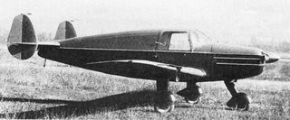
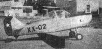
Designed by Hugo Fuentes (hence the HF in the designation), the HF XX-02 trainer was a conventional, low-wing cantilever monoplane of mixed construction with fixed tailwheel undercarriage. The pilot and instructor sat side by side.

Two prototypes were constructed at El Bosque Air Base, designated XX-02 and XX-02B, and the first flew in 1954. Development was abandoned due to difficulties maneuvering at lower altitudes, which in one case, led to a crash in which the instructor was killed while attempting to land after a tight turn at low altitude.

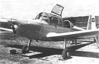
The design was subsequently refined by Francisco Bravo and an improved version, the HFB XX-02 flew in 1958 powered by a Continental O-470 engine in place of the Ranger L-440 that powered the original. Only the two were ever built.

HFB XX-02
Engine: 1 × Continental O-470-B, 168 kW (225 hp)
Wingspan: 10.10 m (33 ft 2 in)
Length: 6.60 m (21 ft 8 in)
Height: 2.15 m (7 ft 1 in)
Wing area: 16.0 m2 (172 ft2)
Empty weight: 760 kg (1,675 lb)
Gross weight: 1,060 kg (2,337 lb)
Maximum speed: 195 km/h (121 mph)
Range: 800 km (500 miles)
Service ceiling: 4,570 m (15,000 ft)
Crew: Two, pilot and instructor

Maestranza Central De Aviacion Triciclo-Experimental / XX-01

In 1947, the Maestranza Central de Aviación, the Central Workshops of the Chilean Air Force designed and built the first Chilean-designed aircraft, the Triciclo-Experimental (also designated XX-01), unveiled in May 1947. The Triciclo, designed by Alfredo D. Ferrer, was a low-winged monoplane of wooden construction with a fixed tricycle landing gear and a twin tail. The crew of two sat side-by-side in an enclosed cockpit, and were provided with dual flight controls.

Built with indigenous materials, Ferrer received tuition in the XX-01.

Only one was built.

Engine: 1 × Franklin, 75 kW (100 hp)
Propeller: two-blade
Length: 6.50 m (21 ft 4 in)
Wingspan: 11.0 m (36 ft 1 in)
Height: 1.80 m (5 ft 11 in)
Wing area: 13 m2 (140 sq ft)
Empty weight: 355 kg (783 lb)
Gross weight: 600 kg (1,323 lb)
Maximum speed: 180 km/h (112 mph; 97 kn)
Cruising speed: 160 km/h (99 mph; 86 kn)
Range: 1,000 km (621 mi; 540 nmi)
Service ceiling: 5,500 m (18,045 ft)
Crew: 2

Maer The Egg / The Fly

A machine built around 1924, consisting of an egg-shaped fuselage with an underslung gondola and extra-long landing gear that could be found at Stinson Field at the time. A mid-wing monoplane, the 90hp Curtiss OX-5 engine was mounted in a cowl that looked much like a NACA cowl, not then invented, and its radiator was mounted on the outside of the cowl.

The ship was said to be the brainchild of a German inventor, and one named Maer was known to be working at Stinson Field, but other sources credit it to a Prof Warner, who also designed an ornithopter.

An Air Service Newsletter lists the plane as “The Fly,” designed and constructed by a Lt D B Phillips, assisted by members of the 3rd Attack Group.

Reportedly was Charles Lindbergh who labeled it “The Egg” when he saw it.

Maeda Ku-1

Professor Hirosho Sato of the Imperial university engineering college at Kyushu designed an assault glider for the Imperial Japanese Army (IJA) in response to news of airborne assaults in Europe.

The Ku-1 was built almost entirely from wood / plywood and was a high-wing glider with twin boom tail sporting a fin and rudder at the end of each boom, with a tail-plane and elevator between the boom ends. The fuselage pod was given a streamlined shape, but with flat sides and a cockpit for two forward of the wing. The undercarriage consisted of two spatted main-wheels on short axles either side of the fuselage, with skids at nose and tail ends of the fuselage pod. The booms, attached to the wing centre-section, were wire-braced horizontally and the fins were braced by short struts on the inboard faces. Passengers and cargo were housed in the cabin below the wing, aft of the cockpit. The three-piece wing consisted of the centre-section, attached to the fuselage pod and two outer panels which were tapered and carried the ailerons for roll control.

Ku-1-I

The prototype was manufactured by Maeda Aircraft Corporation designated Ku-1 (Ku – from Kakku – to glide) and first flew on 9 January 1941. The Ku-1 was tested at the Tachiari military airfield at Kyushu on 1 September 1941. Once accepted for production the glider was given the long designation Maeda Army Type 2 Small Glider.

Maeda Ku-1 Type 2

It was primarily used for training, and was superseded by the Kokusai Ku-7, which was effectively a scaled-up version of the design. Approximately 100 were produced.

Variants:

Ku-1-I
Baseline production glider;100 built.

Ku-1-II
Transparent nose, single tail boom and longer fuselage, prototype only.

Ku-1-III
An aerofoil section fuselage with tapered wings, prototype only.

Specifications:

Ku-1
Capacity: 8 troops, equipped / 600 kg (1,320 lb) cargo
Length: 9.75 m (32 ft 0 in) fuselage
Wingspan: 16.76 m (55 ft 0 in)
Wing area: 30.1 m2 (324 sq ft)
Aspect ratio: 9.7
Empty weight: 698.5 kg (1,540 lb)
Gross weight: 1,297 kg (2,859 lb)
Never exceed speed: 177 km/h (110 mph, 96 kn)
Maximum towing speed: 129 km/h (80 mph; 70 kn)
Crew: 2
Payload: 6-8 paratroopers or 500 kg