Malmo Forsknings & Innovations AB founded by Bjorn Andreasson, intended to put MFI-11 lightplane into production (first flown 1992) as modern version of MFI-9B, but program halted.
Monoplane
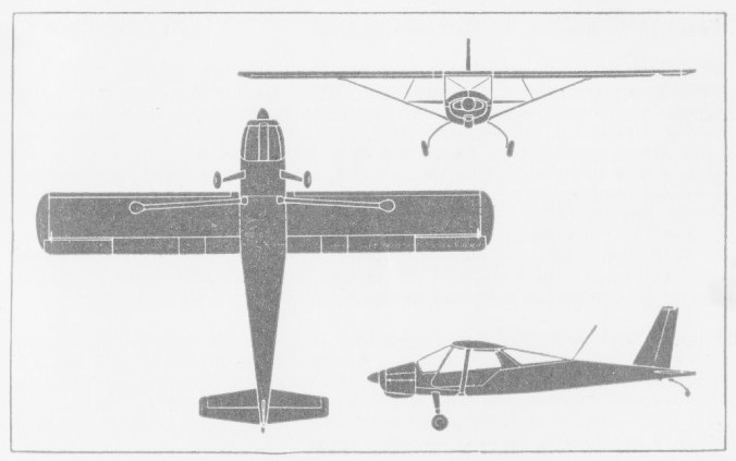
MFI MFI-10 Vipan

Employing formed honeycomb skins to carry virtually all structural loads in the external surface iof the airframe, the Vipan (Peewit) has no wing spar as such and features a continuous, one-piece cantilever undercarriage of glass-fibre reinforced plastic.
A four-seat cabin monoplane, the first prototype, powered by a 160 hp Lycoming O-320-B2B engine, flew on 25 February 1961.
Two further prototypes, with 180 hp Lycoming O-360 engines, were produced under a Swedish Army contract, the first flying on 27 June 1962.
MFI-10B
Engine: 180 hp Lycoming O-360-A1D
Wingspan: 35 ft 1.5 in
Length: 26 ft 1 in
Height: 6 ft 5 in
Wing area: 168.993 sq.ft
Empty weight: 1433 lb
Normal loaded weight: 2280 lb
MTOW: 2590 lb
Max speed: 142 mph at 7500 ft
ROC: 950 fpm
Range: 620 mi at 130 mph
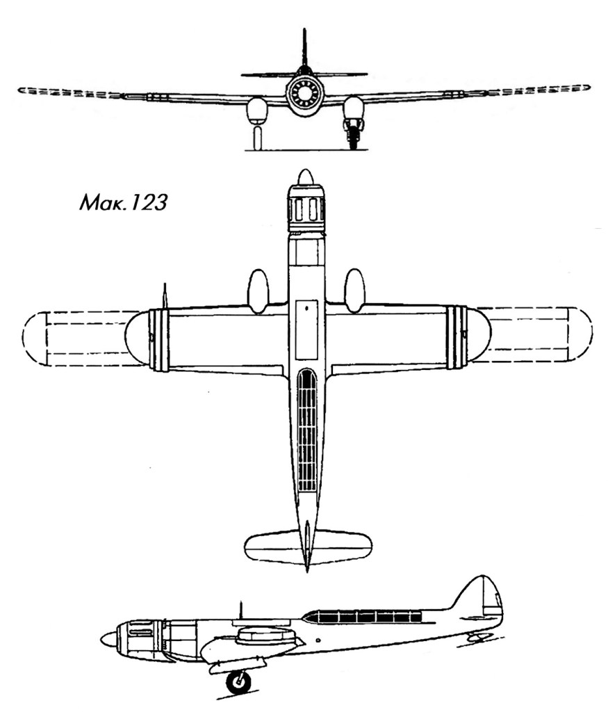
Makhonine Mak-123
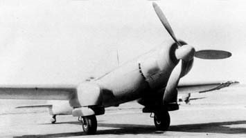
At the end of the war, Ivan Ivanovich Makhonin, with the support of the French Aviation Ministry, built in 1947 a 4-seat Mak.123 aircraft based on the same principles as his predecessors Mak.10 and Mak.101.
A device with a variable wing length (the wing length varied from 13 to 21 m, and the area from 20 to 36 sq.m) and a captured BMW 801 engine with a power of 1800 hp. tested in the same year.
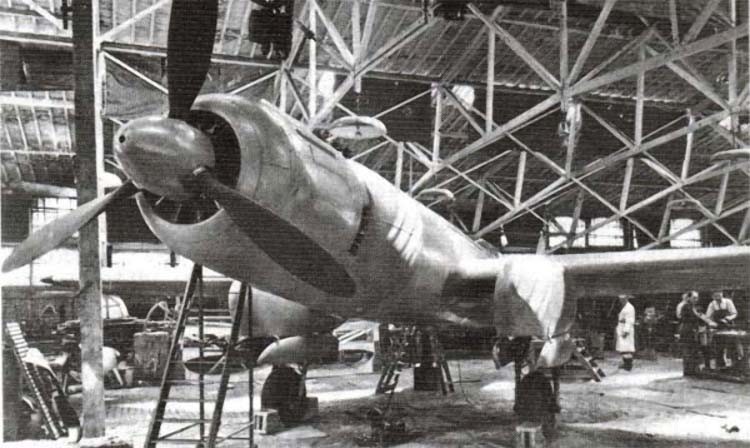
First flying in 1947, the original feature of the aircraft was the cabin with a tandem landing (one behind the other) of all four crew members.
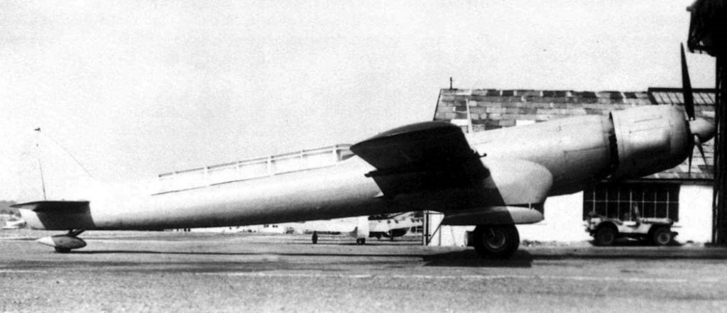
It was assumed that Mak.123 could become the base model for a promising reconnaissance aircraft, but the inventor failed to continue research and the project was terminated after it crashed and not re-built.
Engine: BMW 801, 1800 hp
Wingspan: 13.00 – 21.00 m
Wing area: 20.00 – 36.00 sq.m
Empty weight: 7000 kg
Normal take-off weight: 10,000 kg
Maximum speed: 300 km/h
Practical ceiling: 5500 m
Seats: 4
Makhonine Mak-10 / Mak-101

In the early 1930s several designers became interested in the possibility of changing the configuration of wings between take off and fast flight. Two routes were explored, the first primarily involving camber and hence lift coefficient reduction and the other a decrease of wing area by span reduction at high speed. The Makhonine Mak-10 of the second.
The Makhonine Mak-10, was a variable geometry research aircraft, built to investigate variable area / telescopic wings during 1931 in France. Details of the Mak-10 are sparse but its novel feature was a telescopic wing which increased the span for take-off by 8 m (26 ft 3 in) or 60% of its high-speed configuration. The outer panels retracted into the central ones, their inner ends supported on bearings rolling along one or more spars. The ends of the centre section were reinforced with cuffs. The wing apart, it was a conventional cantilever low wing monoplane, with twin open cockpits, the rear one sometimes faired in, and faired, fixed landing gear. It was powered by a 480 kW (644 hp), three bank, W-configuration, twelve-cylinder Lorraine 12Eb engine.

The first flight of the Mak-10 was on 11 August 1931 During four years of development the Mak-10 was re-engined with a 600 kW (800 hp) Gnome-Rhône 14K Mistral Major fourteen cylinder, two row radial engine which gave it a top speed of 380 km/h (240 mph) and the new designation Mak-101.
Mak-10
Engine: Lorraine 12Eb, 480 kW (644 hp)
Propeller: 2-blade
Wingspan: 13 m (42 ft 8 in) retracted
21 m (69 ft) extended
Wing area: 33 sq.m (230 sq ft) retracted
33 m2 (360 sq ft) extended
Gross weight: 5,000 kg (11,023 lb)
Maximum speed: 300 km/h (190 mph, 160 kn)
Crew: 2
Mak-101
Engine: Gnome-Rhône 14K Mistral Major, 600 kW (800 hp)
Propeller: 2-blade
Wingspan: 13 m (42 ft 8 in) retracted
21 m (69 ft) extended
Wing area: 21 m2 (230 sq ft) retracted
33 m2 (360 sq ft) extended
Top speed 380 km/h (240 mph)
Mainguet La Dorade / Sea-bream
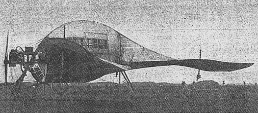
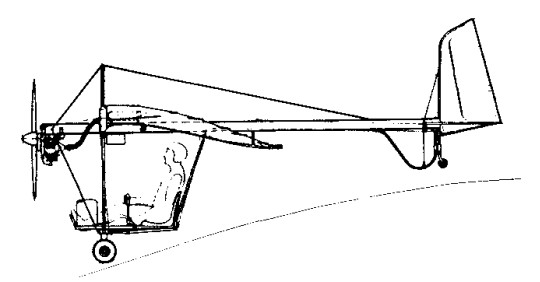
The Henri Mainguet La Dorade / Sea-bream of 1910 was intended to hold ten passengers in an enclosed cabin. Distinctive for its bulbous fuselage and lack of a stabilizing vertical tail fin, the pilot was seated outside, at the nose of the all-covered fuselage, the engine set out above him.
The passengers sat in the enclosed cabin with mica windows which made up the bulk of the streamlined guppy fuselage; aft, it tapered down to a long sweeping horizontal tail. No vertical surface appears to have been fitted. The oval somewhat drooping wings were mounted at a very high angle of attack, and had wheels set below the tips; the whole machine was resting on a long skid with two trailing wheels forward and one under the rear of the cabin. The engine seems to have been a 40 hp 3-cylinder Anzani. With a higher-powered engine, Mainguet at first succeeded at first only in running into the trees, and later in some prolonged hops.
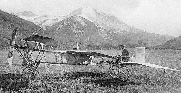
Henri Mainguet built this tractor monoplane, in 1910 at Chartres: it appeared for the first time on 21 May.
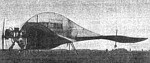
It flew but without passengers.
Mahrer HB-1340 Delphin
This single-seater sailplane is an experimental variable-geometry version of the Swiss Neukom S-4A Elfe 15, and was first flown by Herr Fritz Mahrer on 6 May 1977.
It is basically a modified Neukom S-4A with new 15m span wings; these have Eppler wing sections similar to those on the Neukom AN-66C Super-EIfe, and are fitted with area-increasing Fowler-type flaps actuated electrically. When extended these flaps increase the wing area from 107.6sq ft to 121.6sq ft, and the aspect ratio of 22.5 with flaps in becomes 19.9 when they are extended.
The Delphin also has a T-tail unit similar to that of the Schempp-Hirth Cirrus replacing the Neukom S-4A’s low-set tailplane, thus avoiding tailplane buffeting when the flaps are extended. Construction of the Delphin is mainly of plastics materials.
Span: 49 ft 2.5 in
Wing area: 107.6 sq.ft (flaps in) / 121.6sq ft (flaps out)
Aspect ratio: 22.5 (flaps in) / 19.9 (flaps out)
Empty weight: 617 lb
Mahoney-Ryan X-1 Special / Sportster
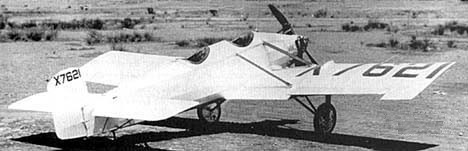
The 1928 X-1 Special aka Sportster experimental lightplane was designed by Don Hall and first flown in September 1928 (piloted by Red Harrigan, registered NX7621). Power was an 80hp Siemens-Halske.
Repowered with 90hp Warner Scarab as a 1929 Safety Plane entry with a variable-airfoil wing (“no two ribs are alike”) controlled by a lever in the cockpit. No fin or stabilizer, which were replaced by a large, moveable “stabilator” and a longitudinally adjustable 50 lb weight on a track to shift the c/g. All that resulted in enough stability problems to cancel the project.
Only the one was built, reportedly flown several times by Charles Lindbergh.
Wing span: 27’0″
Length: 22’0″
Max speed: 135 mph
Seats: 2
Mahe Pfadfinder
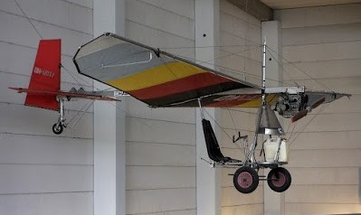
Single seat single engined high wing monoplane with two axis control. Wing has unswept leading edge, swept forward trailing edge, and tapering chord; conventional tail. Pitch control by fully flying tail; yaw control by fully flying rudder; no separate roll control; control inputs through stick for pitch/yaw. Wing braced from above by kingpost and cables, from below by cables; wing profile single surface. Undercarriage has three wheels in tail dragger formation, with suspension on tailwheel and steel spring suspension on main wheels. No ground steering. An aluminium tube framework, without pod. Engine mounted below wing driving tractor propeller.
The Pfadfinder is in fact a version of the Australian Scout built under licence in West Germany by Mahe.
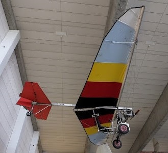
The Pfadfinder uses a noticeably different wing from the original Scout and is fitted with the Konig SC430 engine. Used at 4400 rpm, this gives 27 hp with a three blade ground adjustable propeller. Options include floats, instruments, and a document and map case.
Length overall 17.1 ft, 5.22 m.
Height overall 6.9 ft, 2.09 m.
Wing span 28.4 ft, 8.67 m.
Chord at root 5.7ft, 1.75m.
Chord at tip 1.3 ft, 0.41 m.
Sweepback: 0 degs.
Tailplane span 10.7ft, 3.25m.
Fin height 4.9 ft, 1.50m.
Total wing area 125 sq.ft, 11.6 sq.m.
Rudder area 8.3 sq.ft, 0.77 sq.m.
Total elevator area 17.0 sq.ft, 1.58 sq.m.
Wing aspect ratio 6.5/1.
Wheel track 4.8 ft, 1.47 m.
Wheelbase 12.5 ft, 3.78 m.
Tailwheel diameter overall 11 inch, 27 cm.
Main wheels diameter overall 11 inch, 27 cm.
Engine: Konig SC430, 27 hp at 4400 rpm.
Propeller diameter 51 inch, 1.30 m.
Belt reduction, ratio 1.511.
Max static thrust 155 lb, 70 kg.
Power per unit area 0.22 hp/sq.ft, 2.3 hp/sq.m.
Fuel capacity 2.6 US gal, 2.2 Imp gal, 10.0 litre.
Empty weight 132 lb, 60 kg.
Max take off weight 375 lb, 170kg.
Payload 243 lb, 110kg.
Max wing loading 3.00 lb/sq.ft, 14.7 kg/sq.m.
Max power loading 13.9 lb/hp, 6.3kg/hp.
Load factors; +6.0, NC ultimate.
Max level speed 56 mph, 90 kph.
Never exceed speed 65 mph, 105 kph.
Max cruising speed 56 mph, 90 kph.
Economic cruising speed 47mph, 75kph.
Stalling speed 28 mph, 45 kph.
Max climb rate at sea level 500 ft/min, 2.5 m/s.
Best glide ratio with power off 7/1.
Take off distance 130 ft, 40 m.
Landing distance 82 ft, 25 m.
Range at average cruising speed 112 mile, 180 km.
Magnan Zézé 1
Little is known about the “Zézé 1” tandem wing monoplane, which was tested at Pont des Arches, near Dignes, Haute Provence, France, probably in 1910.

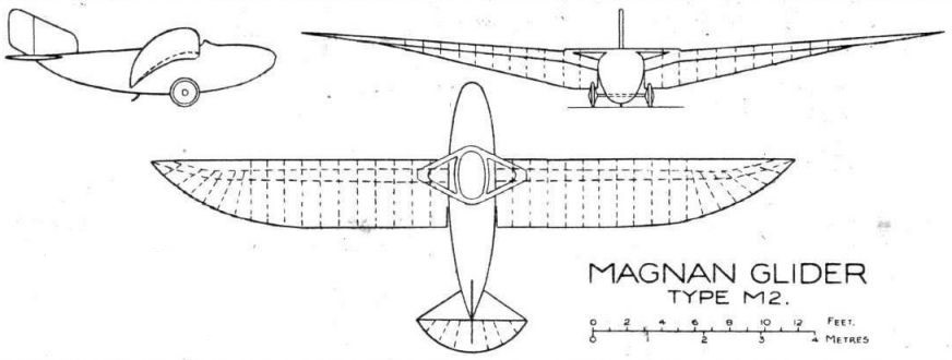
Magnan M-2 Marin
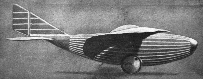
Apart from the studies made in Germany, several French experimenters have attacked the problem of “gust-soaring,” among them being Dr. Magnan, who has made a close study of bird flight, and who reached a stage when he could justify the building of a machine for the purpose of carrying out actual flying experiments. This machine is of unorthodox design, both aerodynamically and structurally.
Basing his design to some extent upon birds, in 1921 Dr. Magnan produced a cantilever monoplane, the wing of which is of uniform chord over approximately one-half of its span, but tapering to a point at the tips. The leading edge is straight and the taper is provided solely by the trailing edge. Near the root the wing is swept down suddenly and sharply to form a pronounced dihedral angle. This angle extends over but a few feet of the span, and the rest of the wing is at a smaller dihedral. The wing tapers in thickness as well as in chord, and the angle of incidence is progressively altered, being around 20 degrees at the root. In addition to the change in section and angle, the wing ribs are so constructed that they are capable of being flexed to an extent under varying loads. No ailerons are fitted. Lateral control is by wing warping.
The fuselage is short in proportion to the span, and a large portion of it projects ahead of the wing. This results in the tail being very close to the wing, only about one chord-length separating the trailing edge from the forward end of the fixed tail plane. A large rudder is fitted. The “fin area” of the forward portion of the fuselage is very considerable, of rounded section.
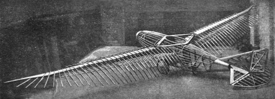
The monoplane wing has but a single spar, of box section and built of wood. There are two fairly sharp bends in each spar, one a few feet out from the body, where the horizontal cabane meets the spar, and another a few feet from the tip, where the spar tip is swept forward to meet the straight leading edge. The ribs have top and bottom flanges of ash, the lower flange, which runs from leading to trailing edge, being screwed and glued to the lower face of the spar. The top flange stops short of the trailing edge, about one-third of the chord from it, and is so attached to the lower flange and to the spar that it can slide a short distance in a fore-and-aft direction, thus allowing the trailing edge to flex.
Near the wing tips the ribs slope outwards, and also they are so mounted on the spar as to give a pronounced “wash-out” to the wing. Lateral control is by warping, but instead of the warp causing a change of angle without sensible change in camber, in the Magnan monoplane both angle of incidence and camber are altered. The fabric covering is applied in a way which was claimed to prevent wrinkling when the wing is being warped.
The fuselage is of egg-shape section, and is built up of formers alternating sloping back and forward, thus forming a series of Vees as seen in side view. To these formers are attached four main longerons and a great number of stringers, and wire bracing is employed for stiffening the structure against torsion. The fuselage is fabric covered except at the extreme nose and stern. The tail is of more or less orthodox design, but is supported on a duralumin cone bolted to the rear bulkhead of the fuselage proper.
A simple undercarriage consisting of two wheels carried on a duralumin axle is fitted, the axle being sprung by rubber cords anchored inside the lower portion of the fuselage.
The pilot’s seat is mounted on longitudinal rails, somewhat like the sliding seat in a boat, and for fore-and-aft control he can alter the position of the centre of gravity by sliding the seat along. The ordinary controls are of the usual type.
The machine was to be launched from a cliff on the coast, and glide into the wind until fairly low over the sea. During a gust the pilot would pull back the stick, and if necessary shift his seat back so as to bring the tail down quickly. As a gust dies down he would push the stick forward and slide his seat forward at the same time so as to avoid stalling the machine. During a lull it was to be the pilot’s endeavor to glide forward with the minimum loss of height, i.e., at the best gliding angle for the particular conditions. Dr. Magnan considered that another method would be to glide down-wind during the lulls and up-wind during the gusts, but that it was doubtful if the machine could be manoeuvred quickly enough to make this form of gust-soaring feasible.
Some preliminary tests over land were made with the machine, piloted by Canivet, and these were stated to have indicated that the machine should, under suitable conditions, be capable of taking advantage of a gusty wind.
As alighting on the sea was to be one of the normal functions of the machine, the fuselage and wings have been made watertight, the opening for the wheel axle being bulkheaded off from the rest of the fuselage.
Type Marin M.2
Length o.a., 4-95 m. (16 ft. 3 ins.)
Wingspan, 11-5 m. (37 ft. 9 ins.)
Chord (root), 1-3 m. (4 ft. 3 ins.)
Wing area, 10 -25 sq. m. (110 sq. ft.)
Weight of wing, 60 kgs. (132 lbs.)
Weight of machine (empty) 130 kgs. (286 lbs.)
Weight in flying trim, 200 kgs. (440 lbs.)
Wing loading, 19 kgs./sq. m. (4 lb./sq. ft.).