Margański & Mysłowski EM-10 Bielik

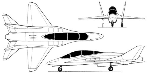
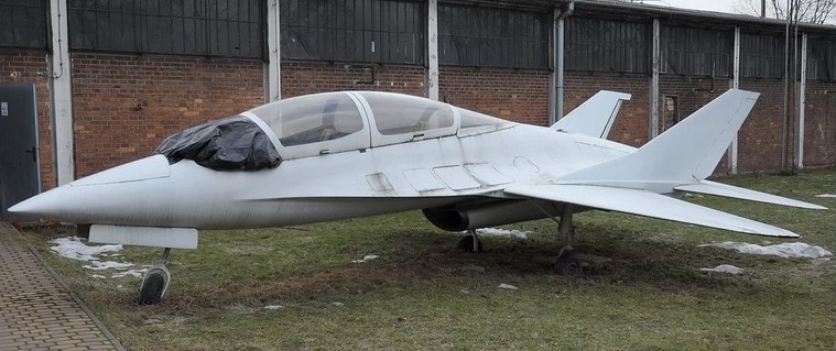
The EM-10 Bielik (English: white-tailed eagle) is a low cost Polish military training aircraft prototype, designed by Edward Margański and built by Margański & Mysłowski Zakłady Lotnicze, first flown on 4 June 2003.

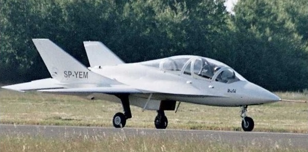
The single engine aircraft has a composite (mostly carbon fibre) fuselage with a light alloy aft section and the pressurized cockpit is fitted with ejection seats.

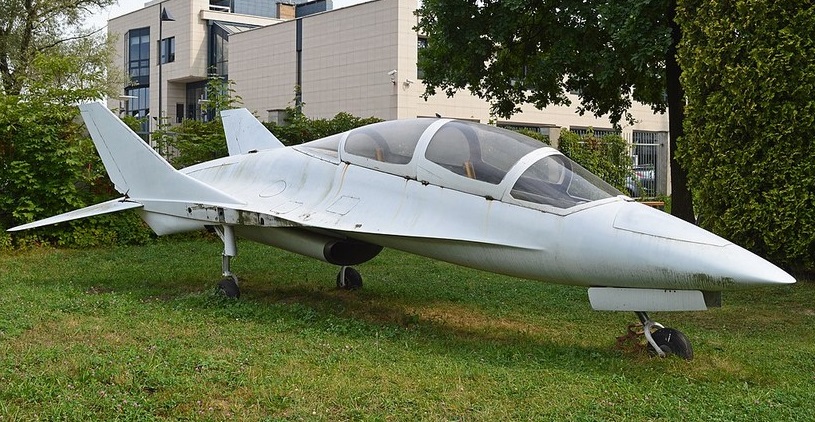
Only one was built, now residing in the Polish Aviation Museum.
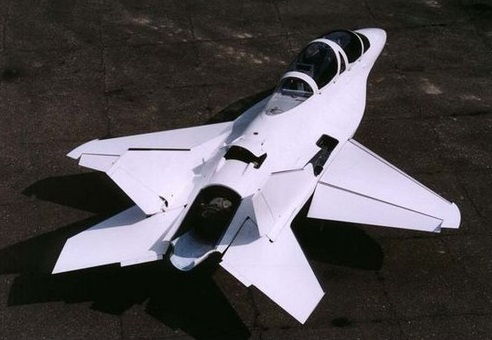
Gallery

EM-10 prototype
Powerplant: 1 × General Electric CJ610-6 turbojet, 13.5 kN (3,000 lbf) thrust
Wingspan: 6.60 m (21 ft 8 in)
Wing area: 11.90 sq.m (128.1 sq ft)
Length: 9.00 m (29 ft 6 in)
Height: 2.50 m (8 ft 2 in)
Aspect ratio: 3.7
Empty weight: 1,700 kg (3,748 lb)
Max takeoff weight: 2,500 kg (5,512 lb)
Fuel capacity: 850 kg (1,870 lb)
Maximum speed: 1,100 km/h (680 mph, 590 kn)
Maximum speed: Mach 0.9
Stall speed: 165 km/h (103 mph, 89 kn)
Ferry range: 2,500 km (1,600 mi, 1,300 nmi) with auxiliary tanks
Rate of climb: 45 m/s (8,900 ft/min)
Wing loading: 210.1 kg/m2 (43.0 lb/sq ft)
Crew: 2

Marendaz Mk.III / Mk.IV

The D. M. K. Marendaz designed four-seat Marendaz III was quite an advanced concept for 1937, but never went into production. Two were built by International Aircraft & Engineering Ltd. at Maidenhead 1937/1938. The first, uncompleted, prototype was destroyed in a factory fire while the second, G-AFGG, although exhibited at the 1938 RAeS garden party, was never completed. The engine was a DH Gipsy VI of 200hp.

Marendaz Mk III G-AFGG Construction Number: 2

Mk.III
Engine: Gipsy Six
Wingspan: 31 ft
Length: 31 ft
Seats: 4

Mk.IV
Engine: Gipsy Major
Wingspan: 31 ft
Length: 31 ft
Seats: 3

Marendaz Trainer

Marendaz company, at Barton-in-the-Clay, Bedfordshire, built prototype Marendaz Trainer two-seat monoplane which first flew December 1939 as G-AFZX c/n A.B.T.1.

The only one built, it was given to the Halton Squadron of the Air Training Corps.

Engine: Blackburn Cirrus Minor I, 90 hp
Span: 34 ft 0 in
Length: 22 ft 4 in
Empty weight: 960 lb
AUW: 1500 lb
Max speed: 124 mph
Cruise: 95 mph

Marçay-Moonen 1911 monoplane

In 1911 the French army wanted to have an aircraft easily transportable and quickly dismountable from one location to another by road or railway. It was also required that the aircraft could be reassembled quickly. Baron Edmond de Marçay and Emile Moonen simplified the problem by imagining a device with wings folding along the fuselage, which was triangular and completely covered. The pilot could fold the wings without help and afterwards, according to the inventors, drive the machine on the road like a car, using the steerable rear wheels. The machine was first presented at the 1911 exhibition.

Manuel Willow Wren

Built by W.L. Manuel, the Willow Wren was a development of the Crested Wren.

A single seat sailplane, the cockpit was deeper, placing the pilot within the fuselage, and the elevators and rear fuselage were revised so enclosing the elevator controls within the fuselage.

The brace wing had no airbrakes or flaps.

The prototype. “Yellow Wren”, first flew in December 1932 from Hawkinge. It became BGA.162.

Manual built a second, “Blue Wren”, BGA.201, which was sold in South Africa as ZS-GAW in 1937. It was written off in April 1949.

Several others were built from plans.

Wingspan: 12.2m / 40ft 0in
Length: 6.2m / 20ft 4 in
Wing area: 13.94 sq.m / 150 sq.ft
Aspect ratio: 12
Wing section: Gottingen 549
Empty weight: 95.26 kg / 210 lb
Wing loading: 11.22 kg/sq.m / 2.3 lb/sq.ftt

Manuel Crested Wren

The single-seat Crested Wren was designed and built by W.L. Manuel in 1931. Of conventional wooden construction, it was designed for slope soaring. Strut braced wing, no flaps of air brakes. The undercarriage was a main skid plus tail skid.

It was first flown at Hawking, UK, in July 1931. BGA.178 “Red Wren”.

W.L. Manuel made his first soaring flights in the Crested Wren in November 1931, flying from hills overlooking Folkestone.

The Crested Wren was eventually bought by E. Thomas in 1938.

Wingspan: 12.2 m / 40 ft 0 in
Length: 6.16 m / 20 ft 3 in
Wing area: 13.94 sq.m / 150 sq.ft
Aspect ration: 12
Wing section: Gottingen 549
Empty weight: 86.18 kg / 190 lb
Flying speed: 48 kph / 30 mph

Manuel VI Primary

The Manuel VI Primary was a wire-braced monoplane primary glider designed and built by W L. (Bill) Manuel whilst serving in the RAF in 1930.

The Manuel Primary was a wooden aircraft built around an open, vertical, tapered girder with a horizontal upper member and a lower one shaped at the front into a shallow keel. The girder was strengthened with a series of vertical and diagonal cross-pieces. The keel projected forward of the foremost vertical member and carried the pilot’s seat on its upper edge. The thick-profile wing was attached to the upper part of the girder and was straight edged with constant chord apart from the angled tips of the ailerons. Extensions of two of the forward girder cross-pieces formed a triangular structure over the wing which acted as a king post for a pair of landing wires. Flying wires from the keel and the upper member about half way to the rear of the girder carried the lifting loads on the wing. There were also bracing wires from wing to the rear of the aircraft to restrain horizontal bending of the girder. The rectangular tailplane was likewise fixed to the top of the girder and carried elevators with a cut-out in which the all-moving rectangular rudder, which extended to the lower girder, could operate.

The glider flew for the first time on 30 August 1930 at RAF Hawkinge in Kent, where Corporal Manuel was based. He made many more flights in it and other Channel Gliding Club pilots also flew it. It was finally destroyed in a road accident in the way to a meeting near Brighton in October 1930.

It flew successfully but only one was built.

Wingspan: 39 ft 0 in (11.89 m)
Wing area: 192.5 sq ft (17.88 m2)
Aspect ratio: 7.8
Length: 18 ft 11 in (5.77 m)
Crew: 1

Manuel Condor

One of the pioneer British sailplane designers before the war, Mr W. L Manuel became concerned at the number of fatal accidents in hang gliding, and in the Condor has designed a simple two-seater sailplane intended especially for hill soaring and aimed at meeting the needs of those who would like to fly but who could not afford the price of a modern high performance sailplane, and who do not have the skills or the time to construct one of the homebuilt designs now on offer.

Resembling the primary trainers of the early 1930s in appearance, the Condor has a short boat-shaped fuselage nacelle of metal tube construction with comfortable side-by-side seating for two in an open cockpit; at the rear of the nacelle is a pylon on which the high constant chord wings are mounted, these being braced by V-struts on each side to a keel running under the cockpit. The tail unit is carried on an open girder-type rear fuselage of aluminium tubing, the tail surfaces being of generous area with fabric covered ribs and widechord elevators. The landing gear consists of a bow shaped ash skid under the fuselage nacelle, with rubber rollers as shock absorbers.

The prototype Condor made its first flight in August 1976 and in addition to local soaring has made a number of longer distance flights.

Span: 50 ft 2.5 in / 15.3 m
Length: 21 ft 0 in / 6.4 m
Wing area: 250.0 sq ft / 23.23 sq.m
Aspect ratio: 10.0
Wing section: Gottingen 462
Empty weight: 492 lb / 223 kg
Max weight: 899 lb / 408 kg
Water ballast: None
Max wing loading 17.57 kg/sq.m / 3.6 lb/sq ft
Max speed: 86.5 mph / 75 kt / 139 km/h
Stalling speed: 32 kt / 59 km/h
Best glide ratio: 14:1

Manuel Hawk

Mr W. L. Manuel, who designed the Willow Wren and other gliders during the 1930s, continued working during retirement by designing (1968) and building (1969 at Fairoaks aerodrome, Surrey) the Hawk single-seater, intended for soaring in weak thermals.

The Hawk has a wing of rather low aspect ratio (11.88) and a fuselage that, although well steamlined, is not as slim as some contemporary types. The cantilever shoulder wing is a three-piece wooden structure with a centre section and two outer panels; the single spar is of spruce with a plywood leading edge torsion box and fabric covering aft of the spar, and there are air brakes in the wing upper surfaces. The semi-monocoque fuselage is of spruce covered by plywood, with a non-retractable monowheel for landing. The T-tail is of wooden construction, with a trim tab in the starboard elevator and a small dorsal fin. Instead of the conventional one-piece cockpit canopy, a three-piece one is fitted in which the front and rear sections are fixed one-piece single-curvature transparencies and the hinged middle section is a framed double curve segment.

The undercarriage is a fixed centre main wheel plus a tail skid.

The prototype BGA.1778 c/n 1 was built at Fairoaks in Surrey during 1968-70 and made its first flight at the College of Aeronautics airfield at Cranfield on 25 November 1972. Initial flight tests revealed the need for some modifications, including revised aileron controls, removing the air brakes from the wing under surfaces and increasing the rudder area; further flight testing followed these changes.

Span: 42 ft 0 in / 12.8 m
Length: 20 ft 6 in / 6.25 m
Wing area: 149 sq.ft / 13.84 sq.m
Aspect ratio: 11.88
Wing section: Wortmann FX-61 -184/210
Empty weight: 406 lb / 184 kg
Max weight: 639 lb / 290 kg
Water ballast: None
Max wing loading: 20.95 kg/sq.m / 4.29 lb/sq ft
Max speed: 90 mph / 78.5 kt / 146 km/h
Stalling speed: 31 kt / 57.5 km/h
Max rough air speed: 64 kt / 118.5 km/h
Min sinking speed: 2.53 ft/sec / 0.77 m/sec at 38 mph / 33 kt / 61 km/h
Best glide ratio: 25:1 at 41.7 mph / 36 kt / 66.5 km/h

Mantelli-Fossa MF.1

The Mantelli-Fossa MF-1 was designed by Adriano Mantelli, an experienced aircraft modeller. To fund its construction, Mantelli, his cousin Dino Sirocchi and some other aircraft modellers founded a company named SDAM after their senior partners’ initials. The MF-1 was built by Ennio Fossa in his family workshop. It was a high-wing monoplane, its wing supported centrally on a fuselage pedestal and braced on each side with a faired V strut from beyond mid-span to the lower fuselage. It was mounted without dihedral and was rectangular in plan apart from cropped aileron tips.

The fuselage, rectangular in cross-section though with a rounded decking, was entirely fabric-covered. There was an open cockpit immediately ahead of the pedestal. Aft of the wing the fuselage tapered to the tail, where a triangular tailplane with rectangular elevators was placed on top of it. The fin was small and triangular and carried a straight-edged balanced rudder which extended down to the keel, operating in an elevator cut-out. The MF-1 landed on a conventional wooden skid fitted with rubber shock absorbers, assisted by a very small tail skid.

Mantelli flew the MF-1 for the first time on 14 August 1934. Later that year he competed in it at Cantù in the Littoriali Contests.

Only one was constructed.

Wingspan: 11 m (36 ft 1 in)
Wing area: 16.50 m2 (177.6 sq ft)
Aspect ratio: 7.3
Length: 5.70 m (18 ft 8 in)
Empty weight: 95 kg (209 lb)
Gross weight: 170 kg (375 lb)
Maximum glide ratio: estimated 16:1
Wing loading: 10.30 kg/m2 (2.11 lb/sq ft)
Capacity: One