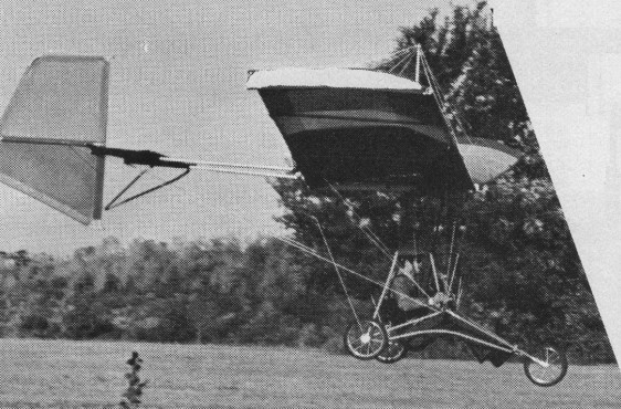
A monowing using weight shift and rudder control. The separate rudder is all flying and there are no ailerons, spoilers or wing warping to achieve roll. Construction is of aluminum tubing covered with dacron on the wings and tail surfaces. Power is a Yamaha mounted in pusher position forward of the wing. A 2:1 reduction unit turns a two-blade, wooden Ritz propeller. Fuel is carried in a plastic tank mounted above the wing. LANDING GEAR: Tricycle type shock mounted with spring action and a bicycle squeeze-type brake. The main and nose wheels are 16 inches in diameter.
In 1981 the complete MAC LST 400 sold for US$2995.
September 1982
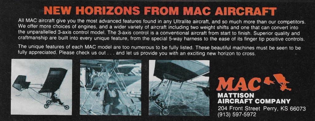
All MAC ultralites convert to floats in minutes. Mac un-breakable floats retailed for $495.00 and fit any ultralite that has a main gear axle.
Each MAC. LST 400 series aircraft is built with 90% straight tubing joined with special fittings to allow faster assembly time, easier parts replacement and lower cost all around. Replacement parts consist of one straight tube to be cut and drilled to size. Special features are a spring shock system, sturdy all round construction. Simple engine mounting, quick folding for storage, all bags and covers included.
The MAC. MU-200 series is a sturdy constructed aircraft that has rear axle shock system, fashionable design with all the features of the 400 series. The MU-200 comes with or without the droop tips. The MU is fun, easy to fly and economic to own and operate.
The MAC. LST-300 series three axis control ultralight, everything before this was just a prototype. All the best features, design and prices. Conventional aircraft looks and operation. Just what the conventional pilot has been waiting for. A one place aircraft anyone can afford to fly. Electric start available in 40 H.P. models.
MAC Wingspan, 32 ft Wing area, 16.7 sq.ft Aspect ratio, 7.1 Overall length, 16 ft Empty weight, 165 lb Usable payload (include fuel), 300 lb L/D power-off glide ratio, 7:1 Cruise speed (85% power), 32 mph Stall speed, 16 mph Approach speed, 16 mph Flair speed, 10 mph Liftoff speed, 18 mph Takeoff roll distance, 100 ft Rate of climb, 300 fpm Fuel capacity, 3 Usgal Range at cruise, 75-100 mi Engine displacement, 100cc, 15 hp Static thrust, 120 lbs.
MU-215 15 hp Cruise speed: 35-45 mph Stall speed: 17-19 mph Take off: 18-22 mph Take off: 50-100 feet Landing roll: 25-50 feet Climb: 300-350 fpm
MU-230 30 hp Cruise speed: 35-55 mph Stall speed: 17-19 mph Take off: 18-25 mph Take off: 30-75 feet Landing roll: 30-60 feet Climb: 650-750 fpm
MU-240 40 hp Cruise speed: 40-60 mph Stall speed: 18-20 mph Take off: 18-30 mph Take off: 30-75 feet Landing roll: 30-75 feet Climb: 750 fpm
LST-315 15 hp Cruise speed: 35-45 mph Stall speed: 17-19 mph Take off: 18-22 mph Take off: 50-100 feet Landing roll: 25-50 feet Climb: 300-350 fpm
LST-330 30 hp Cruise speed: 35-55 mph Stall speed: 17-19 mph Take off: 18-25 mph Take off: 30-75 feet Landing roll: 30-60 feet Climb: 650-750 fpm
LST-340 40 hp Cruise speed: 40-60 mph Stall speed: 18-20 mph Take off: 18-30 mph Take off: 30-75 feet Landing roll: 30-75 feet Climb: 750 fpm
LST-415 15 hp Cruise speed: 35-45 mph Stall speed: 17-19 mph Take off: 18-22 mph Take off: 50-100 feet Landing roll: 25-50 feet Climb: 300-350 fpm
LST-430 30 hp Cruise speed: 35-55 mph Stall speed: 17-19 mph Take off: 18-25 mph Take off: 30-75 feet Landing roll: 30-60 feet Climb: 650-750 fpm
LST-440 40 hp Cruise speed: 40-60 mph Stall speed: 18-20 mph Take off: 18-30 mph Take off: 30-75 feet Landing roll: 30-75 feet Climb: 750 fpm
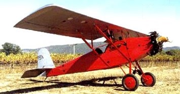
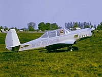
The sold 1929 Matthieu-Russell N996N c/n A-1 was designed by Russel, built by Matthieu. It was sold to Howard P Minnich in the early ’30s and was restored to flying condition in California c.2000.
It was originally powered by a 40hp Szekely SR-3 but has since been re-powered with a 40 hp Salmson AD9. A speed of 85 mph has been reported.
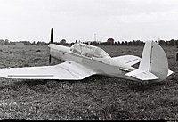
Single seat single engined high wing mono¬plane. Wing has unswept leading and trailing edges, and constant chord; cruciforin tail. Undercarriage has three wheels in tricycle formation. Aluminium tube framework. En¬gine mounted below wing driving pusher propeller. Other details depend on builder’s specifications. Lyle Mathews sells sets of plans of ultralights for homebuilders and this machine which he has designed himself leaves the choice of weight¬shift, hybrid or conventional control system to the constructor, depending on how he or she builds the control surfaces. Lyle Mathews’ CCC (Cross Country Cruiser) can be described as a high wing monoplane with a rectangular wing form and a cruciform tail with tricycle undercarriage; it uses ‘tradition¬al’ tube and fabric construction. It is intended to receive 15 to 30 hp range engines in pusher configuration, mounted on the rear tubes of the pilot frame. The plans are sold in the USA and Canada for $15 and in other countries for $20 in 1982. The data for each CCC depend on how the constructor has chosen to build the aircraft.
Engine: Lloyd, 22 hp Wing span 34.0ft, 10.36m Constant chord 5.0 ft, 1.52 m Sweepback 0 degs Total wing area 165 sq.ft, 15.3 sq.m Wing aspect ratio 7.0/1 Empty weight 1691b, 77kg Max level speed 52 mph, 83 kph Cruising speed 35 mph, 56 kph Stalling speed 22 mph, 35 kph Max climb rate at sea level 350 ft/min, 1.7 m/s Take off distance 90 ft, 27 m.
In 1988, the purely human powered Daedalus, a light-weight aircraft built by a team at the Massachusetts Institute of Technology, flew 71.5 miles from the Greek island of Crete to Santorini. The 69 lb craft, peadeled by a Greek Olympic cyclist, got caught in turbulence as it approached the beach at Santorini. It crashed in the sea a few yards from shore.
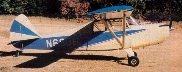
Christavia was designed by Ron Mason around the classic lightplane lines of yesteryear, but with updated performance. It was specifically designed with missionary flying in mind. Mason describes it as a con-ventional, high-wing, strut-braced monoplane easily converted from wheels to floats or skis. All materials are standard off-the-shelf or easily obtainable. Industrial mild steel tubing in the fuselage keeps costs at a minimum; all parts can be made in a small workshop with just hand tools and a welder. No machining is required.
The Christavia was designed in 1982 as a mission field workhorse. Design requirements were short take-off and landing, small engine (low fuel consumption), low stall speed, good cruise speed and rate of climb, large cabin area, low maintenance and high safety factor. The Christavia is easy to fly, and the Iarge cabin makes long flights very comfortable.
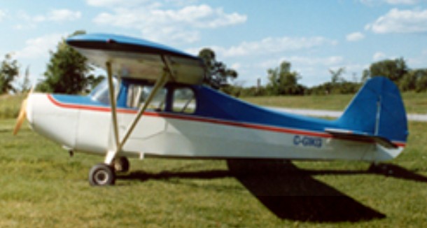
Christavia Mk.2
Over 1000 sets of the plans have been sold for the MK1 (two place tandem), MK2 (two place side-by-side), and Christavia MK4 (four place).
For the MK-2 side by side seating version of the MK-1, increase all crossmembers in the fuselage by 35% for approximate materials requirements. No separate materials list is available for the MK-2.
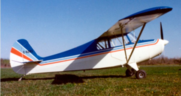
Christavia Mk.4
Aircraft Spruce & Specialty Co. has acquired the design rights to the popular Christavia MK1, Christavia MK2, and Christavia MK4 homebuilt aircraft from the designer, Ron Mason of Elmwood Aviation in Canada.
Mk.1 Engine: Continental, 65 hp HP range: 65-100 Height: 7 ft Length: 21 ft Wing span: 32.5 ft Wing area: 146.2 sq.ft Weight empty: 720 lbs Gross: 1500 lbs Fuel cap: 19 Imp.G Speed max: 118 mph Cruise: 105 mph Range: 315 sm Stall: 40 mph ROC: 900 fpm Take-off dist: 300 ft Landing dist: 600 ft Service ceiling: 14,000 ft Seats: 2 tandem Landing gear: tail wheel.
Mk.2 Seats: 2 Side by Side
Mk.4 Engine: Lycoming, 150 hp Height: 7 ft Length: 22 ft Wing span: 35.5 ft Wing area: 177.5 sq.ft Weight empty: 1100 lbs Gross: 2150 lbs Fuel cap: 37 Imp.G Speed max: 128 mph Cruise: 118 mph Range: 400 sm Stall: 40 mph ROC: 800 fpm Take-off dist: 450 ft Landing dist: 800 ft Service ceiling: 19,000 ft Seats: 4 Landing gear: tail wheel.
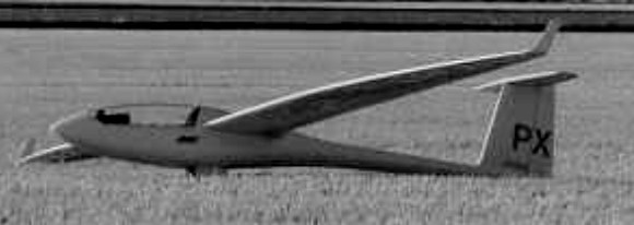
Built by Peter Masak, the Scimitar is a 15 m racing class sailplane which matches an advanced Discus planform wing with electronic boundary layer control married to a Schempp-Hirth Ventus fuselage. The Scimitar II is a Standard Class sailplane developed form the Scimitar I.
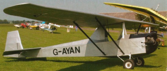
Another motorised version of the basic Cadet/Tutor airframe was the Slingsby/Martin Motor Cadet Mk 3, which was a T31B Tandem Tutor acquired from the Dorset Gliding Club in 1970 and converted by P. J. Martin and D. R. Wilkinson at Twinwood Farm aerodrome, Bedfordshire, to have a 1,600cc Volkswagen engine in the nose. It was now a single seater ultra-light, the front seat being replaced by a 6.5 gallon fuel tank, and a Luton Minor’s undercarriage was fitted to give airscrew clearance.
Registered G-AYAN and named ‘Thermal Hopper’, the sole Cadet Mk 3 received its Authorisation to Fly on 15 January 1971.
The X 24A and X-24B were the forbears of the Orbiter because they were conceived, designed, built, and flown as part of the Air Force NASA effort to develop a vehicle which could re enter the earth’s atmosphere from space and be flown without power to a selected landing site.
Both vehicles were lifting bodies. They do not use wings to achieve lift, but rely entirely on body shapes to produce lift with as little drag as necessary. What was needed was a type of aerodynamic shaping to cope with the high heat of re entry, while still producing a flying machine that could be control¬led by the pilot. The X 24 flight test programmes proved that the designs were correct.
In the form of the Martin Marietta Corporation, Martin returned to piloted aircraft production in 1965 with SV-5 piloted lifting body research vehicle, built as SV-5J with J-85 or J-60 jet engine and as SV-5P or X-24A with XLR-11 rocket engine. The X 24A and B, designed to be carried aloft by a Boeing B 52 and launched at about 45,000ft, made a ¬total of 64 successful flights and landings, sometimes using rocket power to go up to 60,000 or 70,000ft and increase their speed to simulate re entry conditions before starting their approach to a powerless landing.
The X 24A had medium lift to drag ratio (4.5 at subsonic speeds and 1.3 at hypersonic speeds), and could land anywhere within an area 8,000 nm long and 4,000nm wide from the point of re entry.
The flights of the two aircraft pro¬vided research data in the lower end of the re entry flight corridor, from low supersonic speeds through tran¬sonic and subsonic, speeds to landing. This data simplified the task of de¬signing and building the Space Shuttle Orbiter.
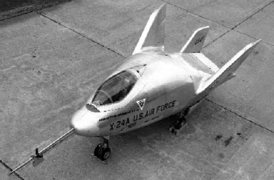
The X-24A/SV-5P represented the low-speed end of the test spectrum for the START program that had also tested the X-23A. The X-24A was used in project PILOT (piloted low-speed tests). The rocket-powered X-24A was specifically designed to explore the low-speed flight characteristics of a maneuverable lifting-body design. The design was essentially identical to the SV-5D used in project PRIME as the X-23A, allowing both ends of the flight spectrum to be tested on the same shape. The X-24A decisively demonstrated that lifting-bodies could consistently make precision landings onto a hard runway, proving the concept for the future Space Shuttle.
The X 24A project began in 1966, while the Air Force and Nasa were already testing two earlier lifting bodies, the M 2 and the HL-10, de¬signed by Nasa and built by Northrop. The X 24A was built for the Air Force by the Martin Marietta Cor¬poration under the management of the Flight Dynamics Laboratory. The design called for a bulbous fuselage, no wings, and a triple tail. The aircraft was 24.5ft (7.47m) long, with a single cockpit well for¬ ward, and had a span of 111.5ft (3.51m).
It was designed to, use the Thiokol XLR-11 RM 13 rocket motor, the same type as that used on the first rocket powered aircraft, the Bell X 1, and which produced 8,600 lb of thrust, burning a mixture of water, alcohol and liquid oxygen. The X 24A car¬ried enough fuel for a maximum burn of 137sec, but this was in-creased to almost 160sec later in the programme. The rocket and fuel brought the maximum launch weight of the X 24A to 11,450 lb, but the rocket was not used in the early flights.
Although it was delivered to Edwards AFB in August 1967, the X 24A did not make its first manned captive flight until April 4, 1969. The first free flight, with Maj Gerry Gentry of the Air Force in the cock-pit, was made on April 17, when it was launched at 45,000ft and an air speed of 174kt with a launch weight of 6,344 lb. The flight lasted 3min 37.4sec, did not go above the launch altitude, and achieved a maximum speed of Mach .718 (411 kt true air speed).
The X 24A made seven more free flights between May and November without using the rocket motor. Gentry was in control for all but one, which was flown by John Manke of Nasa. In January 1970, the engine was run in the aircraft for the first time, but it was flown without the rocket once more before the first powered flight was made by Gentry on March 19.
On that flight, the launch was made at 40,000ft and 175kt at a launch weight of 11,320 lb. The aircraft went up to 44,384ft and achieved a maxi¬mum speed of Mach 0.865 (469 kt) in a flight which lasted 4min 4.25sec.
The X 24A achieved supersonic speed f or the first time on the eighteenth flight, on October 14, with Manke at the controls. It was launched at 42,000ft and 185kt, and went up to 67,900ft and Mach 1.186 (681 kt) before landing after a flight of 6min 51.1sec. On March 29, 1971, it achieved the highest speed of the entire programme, Mach 1.6 (900kt), during the 25th flight, again with Manke at the controls.
The highest altitude the X 24A ever attained was 70,947ft, which it reached during the 26th flight, on May 12. Maj Cecil Powell of the Air Force was the pilot, making his second free flight in the aircraft, and the flight lasted 7min 2.7sec.
The longest flight of the pro¬gramme, lasting 8min 37.2sec, was the 28th and final flight on June 4, 1971, with Manke in the cockpit. When the flight test programme ended after almost two years, the X 24A had flown a total of 2hr 53min.
Only a single X-24A was manufactured, but two extremely similar jet-powered SV-5Js were also built. The SV-5Js were to be powered by a single J60 turbojet engine and used as trainers to introduce pilots to the low-speed handling characteristics of lifting-bodies, but in the end neither aircraft ever flew. One of the SV-5Js is on display at the Air Force Academy near Colorado Springs, Colorado, while the other has been superficially modified into an X-24A and is on display at the Air Force Museum. The X-24A itself was heavily modified to become the X-24B.
X-24B
Although the X-24A program successfully met all of its objectives, engineers and scientists at the Air Force Flight Dynamics Laboratory (FDL) wanted to conduct similar tests on an even more advanced lifting-body shape called the FDL-7/FDL-8. The original plan was to convert one of the jet-powered SV-5Js into the advanced testbed, but since this would have entailed extensive modifications to fit a rocket engine in place of the turbojet, these plans were shelved. As the rocket-powered X-24A was nearing the end of its test program, it was finally decided to utilize it instead since the modifications were expected to be less extensive.
The X 24A was returned to the Martin Marietta plant late in 1971, and the lumpy looking fuselage was literally engulfed by a sleek, needle ¬nosed, wedge like structure. All sub¬systems of the X 24A, with one excep¬tion, were retained in the new vehicle, including the rocket motor. The exception was the nose gear, which had to be beefed up to take the increased weight; it was replaced with the nose gear from a Navy F11F. Strakes just large enough to accommodate ailerons were added outboard of the triple tail.
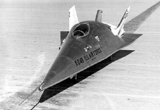
Underneath the sleek shell of the X-24B lived the original X-24A. The new skin was essentially “gloved on” to the original aircraft designed by the Air Force Flight Dynamics Laboratory as the FDL-7/FDL-8. Most systems were retained intact. Although the X-24B was intended to evaluate the flight characteristics of the FDL-7 shape, in reality it spent most of its 36 flights demonstrating precision landing techniques that would be used on the forthcoming Space Shuttle.
The X 24B had a high lift drag ratio (4.8 at subsonic speeds and 2.5 at hypersonic speeds), and had a landing footprint about double that of the X 24A.
The X 24B which rolled out of the plant on October 11, 1972, was 37.5ft (11.4m) long, with the cockpit almost half way back in the fuselage, and had a span of 19.1ft (5.82m). It had a maximum launch weight of 13,800 lb and a landing weight of 8,5001b.
The X 24B flight test programme began in July 1973 with John Manke of Nasa (who had flown 12 of the X 24A flights) and Lt Col Mike Love of the Air Force as primary test pilots, but four other pilots flew the aircraft before the programme ended two years later.
Before Manke made the first free flight on August 1 the craft was taken aloft on two captive flights. The free flight launch was made from 40,000ft at 175kt, and the air¬craft achieved a maximum speed of Mach 0.652 (400kt) and gained no additional altitude before landing in 4min 11.5sec. The first flight to use rocket power was the sixth, on November 15, which was launched at 40,000ft and 185kt and went up to 52,7164ft and Mach 0.917 (519kt) dur¬ing a flight which lasted 6min 44.7sec. Manke was at the controls on that flight and also on the first supersonic flight, the 9th, on March 5, 1974, when Mach 1.086 (615kt) and an altitude of 60,334ft were achieved after a launch from 45,000ft at 184kt.
The highest speed attained by the X 24B was Mach 1.76 (1,164kt) on its 16th flight, on October 25, with Love at the controls. Launched at 45,000ft and 200kt, the aircraft went up to 72,440ft during the 7min 47.6sec flight. The highest altitude reached was 74,130ft on the 23rd flight, on May 22, 1975, with Manke in the cockpit. The launch was at 45,000ft and 195kt and the maximum speed during the flight was Mach 1.63 (942kt). The flight lasted 7min 40. 9sec.
The basic research programme ended on September 23, 1975, with William Dana of Nasa making his second flight as pilot and the air¬craft making its 30th flight, Three other pilots then flew the X 24B for two unpowered flights apiece before it was finally grounded on Novem¬ber 26, 1,975. It had flown 36 flights, the longest of which was 8min 1.9sec, accumulating a total of four flying hours.
The X-24B is currently on display at the Air Force Museum, alongside one the the SV-5Js configured as the X-24A.
X-24A Power: Thiokol XLR-11 RM 13 rocket, 8,600 lb thrust Fuel: water, alcohol and liquid oxygen Maximum burn: 137-160sec Length: 24.5ft (7.47m) Span: 11.5ft (3.51m) Maximum launch weight: 11,450 lb First Flight: 17 April 1969 Last Flight: 4 June 1971 Fastest Flight: Mach 1.60 (1,036 mph) Total Flights: 28 Highest Flight: 71,400 feet
X-24B Length: 37.5ft (11.4m) Span: 19.1ft (5.82m) Maximum launch weight: 13,800 lb Landing weight: 8,5001b First Flight: 1 August 1973 Last Flight: 9 September 1975 Total Flights: 36 Fastest Flight: Mach 1.76 (1,164 mph) Highest Flight: 74,140 feet