PIK Pik-7 Harakka

Magpie I (H-12)

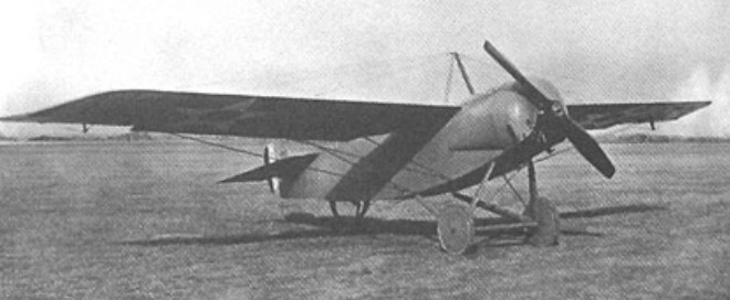
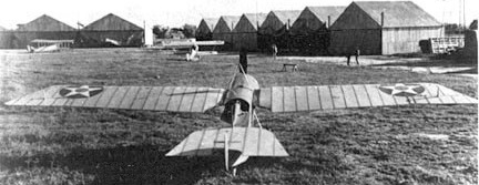
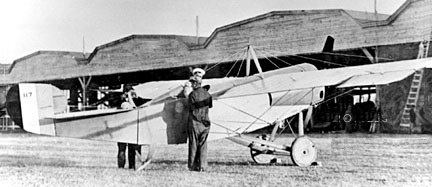
With origins coming from World War II, when Finnish forces took control of the Russian occupied city of Äänislinna. There they noticed a glider pilot school with planes called UC-3s’. They were brought back to Finland and used as a display at the Victory fair.

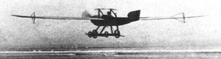
The gliders were then examined and found to be inferior in many ways. One of these UC-3’s was tested and found to be good flier, despite of the inferior build quality and several shortcomings.

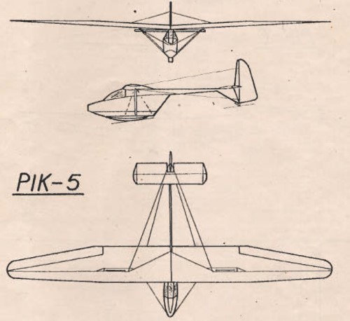
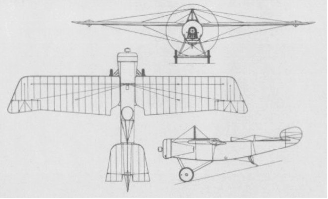
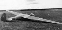
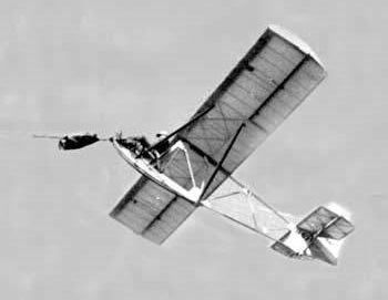
This UC-3 inspired the building of a similar type of primary glider. The key idea was to make it extremely simple, light and easy to build in aviation clubs around Finland, the Harakka (“European magpie”). They did not bother to make plans for the prototype, but just sort of design as you build.

When the prototype was built and it was found to be good flier and better than Grunau’s & SG’s, approx 28 were built.

First flown in February 1945, the type was built from plans by Finnish gliding clubs and soon replaced earlier primary gliders such as the Grunau 9, becoming a standard piece of equipment in the clubs. Approximately 50 were built.

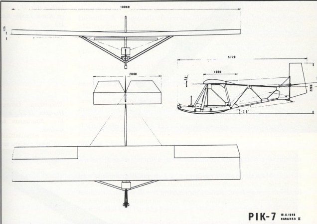
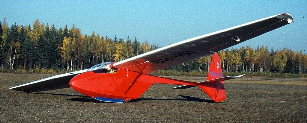
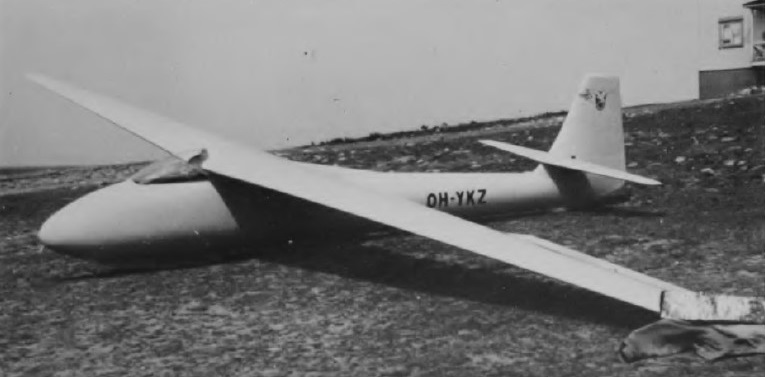
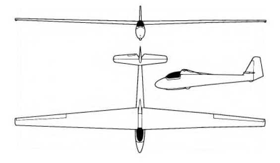
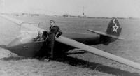
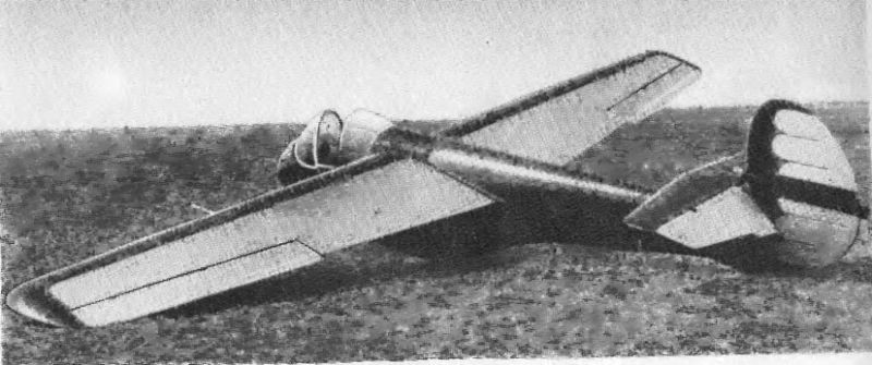
In 1946, booming aviation clubs needed more primary gliders, but the Harakka needed further development and some upgrades to strengthen it. The Local FAA ordered this further development from PIK whose key designers were Juhani Heinonen, J. Nurmi and Raimo Häkkinen. The new plane was called Harakka II and given the PIK-serial number of 7. Twenty-seven were built.

Harakka II

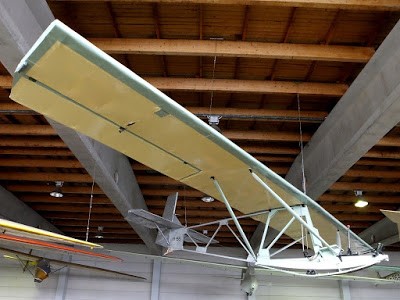
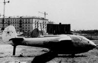
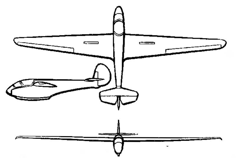
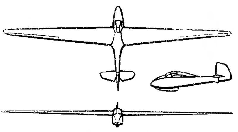
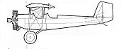
In 1948, a single example of a more radically redesigned version designated Harakka III flew. This had the framework that supported the tail replaced by a single boom.

Harakka III

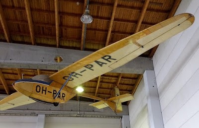
All in all, 57 Harakka’s were built (or started, some were not completed). The last Harakka was a replica built from original plans with designation of H-60.

Harakka III

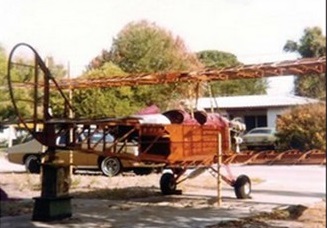
The Moottori-Harakka was a motor glider development of the PIK-7.

Gallery

Harakka
Span: 10.56 m
Length: 5.60 m
Empty weight: 92kg
Start weight: 182 kg
Normal speed: 45 km / h

PIK-7 Harakka II (H-57)
Wingspan: 10.60 m (34 ft 9 in)
Wing area: 15 sq.m (161 sq.ft)
Length: 5.72 m (18 ft 9 in)
Height: 1.30 m (4 ft 3 in)
Empty weight: 92 kg (200 lb)
Gross weight: 200 kg (440 lb)
Maximum speed: 117 km/h (73 mph)
Maximum glide ratio: 10.5:1
Rate of sink: 1.2 m/s (236 ft/min)
Crew: One pilot

Harakka III

PIK Pik-5

Pik-5C

The PIK-5 was a training glider produced in Finland in the 1940s, and 1950s, equipping the country’s gliding clubs with an aircraft greater in performance than primary gliders but less than competition sailplanes. The aircraft had a pod-and-boom configuration, with a high, strut-braced monoplane wing and a cruciform tail carried at the end of a tailboom that extended from a position high on the aft end of the pod.

Designed by Kaarlo J. Temmes, the prototype was built by Polyteknikkojen Ilmailukerho and first flew in September 1946, and testing continued until it was badly damaged in a crash in summer 1948.

Over the subsequent months, the wings were repaired, and a new fuselage constructed to a revised design. This was completed the following winter, and flights recommenced. However, this aircraft, now known as the PIK-5B, was destroyed in a crash in summer 1951.

PIK 5b

Again, it was rebuilt with modifications, particularly to the wing structure, resulting in the PIK-5C version. This version first flew on 5 July 1952, and went on to become the pattern for 34 similar machines that would be built over the ensuing years.

Gallery

PIK-5

PIK 5A

PIK-5B

PIK-5C
Wingspan: 12.4 m (40 ft 8 in)
Wing area: 14.7 m2 (158 sq ft)
Airfoil: Göttingen 533
Aspect ratio: 10.4
Length: 6.4 m (21 ft 0 in)
Empty weight: 120 kg (265 lb)
Max takeoff weight: 210 kg (463 lb)
Stall speed: 45 km/h (28 mph, 24 kn)
Never exceed speed: 190 km/h (120 mph, 100 kn)
Rough air speed max: 120 km/h (74.6 mph; 64.8 kn)
Aerotow speed: 20 km/h (12.4 mph; 10.8 kn)
Winch launch speed: 90 km/h (55.9 mph; 48.6 kn)
Terminal velocity: with full air-brakes at max all-up weight 180 km/h (112 mph; 97 kn)
g limits: +4 -2
Maximum glide ratio: 18 at 60 km/h (37.3 mph; 32.4 kn)
Rate of sink: 0.85 m/s (167 ft/min) at 52 km/h (32.3 mph; 28.1 kn)
Wing loading: 14.3 kg/m2 (2.9 lb/sq ft)
Crew: 1

PIK PIK-3 Kajava / Kanttikolmonen

Pik-3C

The PIK series of sailplanes designed and produced in Finland gets its name from the Polyteknikkojen llmailukerho, the flying club of the Student Union formed at Helsinki University of Technology in 1931; this series started in 1945 and the PIK-3 singleseater, intended for use by and for construction by gliding clubs, was the first to go into series production. It was followed by the PIK-5A, B and C intermediate training sailplanes and the PIK-7 primary glider which, together with the PIK-3, became standard types in the Finnish clubs, and the first two-seater in the series, the PIK-12 trainer.

The PIK-3 was 1942 designed by Lars H ‘Pappa’ Norrmen and Ilkka Lounama, originaly designated LHN-3, the first prototype making its maiden flight in the summer of 1950, and was of conventional wooden construction.

PIK 3a Kanttikolmonen

It was followed by 20 PIK-3A and PIK-3B variants, the 3B, developed by Aush Koskinen, featuring air brakes instead of the 3A’s wing flaps, and both these versions had a 13m (42 ft 7.25 in) span wing.

The PIK-3C Kajava is a high performance version of the 3B incorporating modifications, in particular a wing span increased to 15m (49 ft 2.5 in), to comply with Standard Class rules. The wing structure was completely redesigned and a new cockpit canopy fitted, the fuselage remaining otherwise unchanged from the 3B’s. The prototype PIK-3C first flew on 20 May 1958 and the 3C was modified for series production by Tuomo Tervo at the Suomen llmailuliito (the Finnish Aeronautical Association); 20 had been built by the beginning of 1970. Resembling the EoN Olympia, but with a more angular fin and rudder, the PIK-3C has high-set single-spar wooden wings and an oval-section wooden fuselage with diagonal ply covering, the fin and tailplane also being ply covered.

The PIK-3c combine features of PIK-3b and the PIK-13, and the PIK-3c Kajava (Kittiwake) was a revised high-performance version of the PIK-3Bwith a span of 15 m and a new cockpit canopy.

PIK 3c

Gallery

PIK-3C Kajava
Span: 15.0 m / 49 ft 2.5 in
Length: 6.6 m / 21 ft 7.75 in
Height: 1.0 m / 3 ft 3 in
Wing area: 13.1 sq.m / 141 sq ft
Aspect ratio: 17.1
Wing section: Gottingen 549/693
Empty weight: 165 kg / 364 lb
Max weight: 280 kg / 617 lb
Water ballast: None
Max speed: 155 mph / 135 kt / 250 km/h
Stalling speed: 30 kt / 55 km/h
Max rough air speed: 78 kt / 145 km/h
Min sinking speed: 0.61 m/sec / 2 ft/sec at 40.5 mph / 35 kt / 65 km/h
Best glide ratio: 30:1 at 46.5 mph / 40.5 kt / 75 km/h

Pik-3C

Pigeon-Fraser Albree Scout / Model 9 / Timson-Albree / SG

At a time when the biplane configuration had become the norm for single-seat fighting aircraft, George N Albree designed a single-seat shoulder-wing monoplane intended for use as a fighting scout. Ordered by U.S. Army April 17, 1917, two prototypes were delivered to the US Army Signal Corps by the Pigeon Hollow Spar Company in September 1917.

The aircraft was of wooden construction and powered by a 100 hp Gnome rotary engine. A unique design concept of the aircraft was that the “rudder” was not used for flight control, but only to compensate for engine torque. Also the Scout quite possibly was the very first aircraft design to invoke the use of an all ‘flying tail’ as the entire tail assembly was hinged behind the cockpit moving up and down for elevator control. It is believed to be the first aircraft to utilize a flat-bottomed airfoil, and uniquely designed spring-type wheels were used to provide shock absorption.

Pigeon Scout

First aircraft Model SG- SC-#116 delivered in September 1917 and SG- SC #117 followed in November 1917. First flight: both were flown and successfully tested by contract pilots including Eddie Stinson, at Langley Field, VA. There were no official flights authorized to be made for the U.S. Army acceptance process.

The third Model SG order under the same contract was for a fuselage only, no engine to be provided and with instructions for it to be shipped to the Colt Arms Company, Hartford, CT. The SG fuselage was completed and shipped in the fall of 1917.

The two Model SGs for the Army had their SC Serial #s: high on the vertical stabilizer for #117, and lower for #116). U.S. Army standard aircraft wing star markings for 1917. The first pursuit aircraft contracted for by the United States.

The aircraft was intended to be fitted with a single machine gun, but no armament was ever provided and the Signal Corps considered the aircraft both unreliable and too slow. The fisrt aircraft was tested to destruction, while reportedly the second aircraft was test flown on behalf of the USASC, crashing on its first flight, killing the pilot. The USASC considered the aircraft both unreliable and too slow, consequently, no series production was undertaken.

A third unfinished aircraft was stored in the rafters of the Pigeon Company. It was bought by Cole Palen on November 15, 1961, and restored for display at the Old Rhinebeck Aerodrome Museum.

Albree Scout
50hp Gnôme Pigeon

A Pigeon with 50hp Gnôme engine constructed by Roscoe P Timson and flown at Nahant Beach twice in 1916 by Clifford Webster of Lowell, a test pilot for Burgess Airplane Co.

Of the 4 built, of which 3 for US Army, but were not accepted after testing at McCook Field—one reportedly was a static test model, one crashed and burned in a test flight, one was put in storage by Pigeon Co, and info on the fourth is imprecise, but it could be Albree’s plane. Photos verify the existence of four aircraft, with two of them identified as c/n 9 and s/n 117.

Engine: 100 hp General Vehicle-Gnome rotary
Span: 37ft 11in (11.56 m)
Length: 24 ft (7.32 m)
Height: 8 ft 8.5 in (7.32 m)
Weight T/O: 1250 lb (557 kg)
Speed max: 103 mph (166 kmh)
Seats: 1

Pietsuj PAI-6

Pietsuj with his PAI-6 glider

Between 1947 and 1948, the test pilot and aeronautical constructor Alexei Ivanovich Pietsuj developed two new projects at the MAI that were called PAI-5 and PAI-6 (Russian: Пьецух ПАИ-6).

The PAI-6 was designed as a single-seater training glider to take advantage of thermal flight and had full aerobatic capabilities. It was generally similar to the previous PAI-5, but was notable for its increased wingspan.

The PAI-6 was a high-cantilever glider with a large trapezoidal high-wing.

The glider was built entirely of wood. The fuselage had a simple construction made up of 24 frames joined by three stringers and a set of stringers. The exterior coating was made with plywood between 1.5 and 2 mm thick. The cross section was oval, with downward elongation. In the upper part of the fuselage, a slit was made, crossed by the force elements of the wing. An aluminium cover was placed over this slit.

The wing composition comprised two trapezoidal-shaped consoles in plane joined at their bases on the longitudinal axis of the apparatus. The consoles had a TsAGI R-Sh profile of constant relative thickness (15.5%) and were fixed to the fuselage by means of four points of two reinforced frames located in the upper part. The two consoles were joined together by screws and conical fixings. The fixing points to the frames were located on the spar and on the last wing spar.

The wing featured a single spar structure with ends working by twisting. The stringer was made up of two faces with plywood partitions. The wingtips and the frontal region of the wing were covered with plywood and the rest with fabric covered with paint.

The ailerons were attached to an auxiliary spar at three points and featured a single spar structure with diagonal ribs. The front part was covered with plywood and the rest with fabric. The wing-end interceptors were conceived as smooth pine frames with fabric covering on both sides. Each interceptor was attached to the wing spar by three points.

The horizontal tail plane was raised to the top line of the fuselage and positioned in front of the vertical tail. The stabilizer featured a single spar construction with plywood overlay. The elevators also used a single spar and coating similar to that of the ailerons.

The keel was an integral part of the fuselage construction and ended in a rudder with aerodynamic compensation. This rudder featured a two-stringer structure. From the leading edge to the second spar the covering was plywood and from there on fabric. All rudders featured three-point fixation. The landing was made on a wooden ski, with a trunk structure, located in the lower part of the fuselage.

The cockpit, located in front of the wing, was closed by a cover that protruded from the upper line of the aircraft. The flight control was mixed with control of the ailerons by means of ropes and bars for the control of the tail planes.

The control of the interceptors and the tow hook was also carried out by cables, with actuators located on the sides of the cockpit.

Once the tests were completed from the GK NII VVS Experimental Factory, improvements were made to the original design and the entire set of plans and technical diagrams was created to launch production. In Ryazan, Moscow, a small series was built in 1949. Its main destination was the flying clubs of the country. PAI-6 participated in several air parades for Aviation Day in Túshino.

An improved version of this glider known as PAI-6M was built in the early 1950s at the MAI. This aircraft was never flown and was destroyed as a result of the cooling towards the gliders that occurred in the USSR in those years.

PAI-6
Wingspan: 12.4 m
Wing area: 11.8 m²
Aspect ratio: 13
Length: 5.41 m
Height. 1.35 m
Glider weight: 193 kg
Wing loading: 24 kg / m²
Stabilizer surface: 0.9 m²
Elevator area: 0.75 m²
Keel surface: 0.17 m²
Rudder surface area: 0.85 m²
Spoiler area: 1.58 m²
Minimum descent speed: 0.82 m / s
Cruising speed: 85 km / h
Landing speed: 60 km / h
Max glide ratio: 24
Accommodation: 1

Pietsuj PAI-5

Between 1947 and 1948, the test pilot and aeronautical constructor Alexei Ivanovich Pietsuj developed two new projects at the MAI that were called PAI-5 and PAI-6. The Pietsuj PAI-5 (Russian: Пьецух ПАИ-5) was designed as a single-seater competition glider and was built at the GK NII VVS experimental factory in 1947.

The PAI-5 was designed as a high cantilever glider with a small trapezoidal wing.

The glider was built entirely of wood. The fuselage had a simple construction made up of a series of frames joined by four stringers. The outer covering was made with plywood. The wings had an R-Sh profile. The wingtips were covered with plywood and the rest with paint coated fabric.

The horizontal tail plane was raised to the top line of the fuselage and positioned in front of the vertical empennage.

The landing was made on a wooden ski, with a trunk structure, located in the lower part of the fuselage.

The cockpit, located in front of the wing, was closed by a cover that protruded from the upper line of the aircraft.

The PAI-5 glider was tested in February 1948. Pietsuj himself flew the model in front of a group of renowned test pilots, most notably Air Marshal Ye. During the test flight the complete set of high school aerobatics was executed and an overload of 8g was achieved at speeds of 220 km / h.

During the celebration of Air Fleet Day in 1948 Pietsuj made a demonstration of high school piloting. For the design and construction of this glider AI Pietsuj received the Order of the Red Star.

Pietsuj PAI-3

The Pietsuj PAI-3 (Russian: Пьецух ПАИ-3) was a glider designed and built by Alexei Ivanovich Pietsuj as a single-seater training apparatus for the preparation of Class B sport pilots and was built in 1937.

It was designed with the aim of replacing the Gribovski G-9 and Antonov BS-5 gliders, already outdated for the time. It was necessary to have a training glider capable of being towed from another plane and performing all kinds of high school stunts in all weather conditions.

The PAI-3 was designed as a high-wing cantilever monoplane with a trapezoidal wing and high aspect ratio.

The fuselage had a simple construction made up of a series of frames joined by four stringers. The outer covering was made of 2 mm thick plywood covered with fabric.

The wing construction incorporated a single main spar, a secondary spar, and a set of ribs. To fix the ailerons another small auxiliary spar was used. The wing tip was covered with plywood, but the rest of the coating was made of fabric covered with several layers of paint.

The empennage featured a large rudder attached to the shallow keel at three points. The horizontal empennage featured two non-stabilized elevator rudders.

At the bottom of the fuselage there was a ski with a trunk structure, without amortization.

The spacious cabin featured an angular deck constructed of duralumin and celluloid.

From a production point of view the Pietsuj PA-3 glider was easier and cheaper to produce than the Gribovski G-9 and Antonov BS-5.

The flight tests of the PA-3 glider were developed by pilot PI Shelest. Despite showing good performance, series production was not approved. Only the one prototype was built.

Pietenpol Sky Scout

The 1931 Sky Scout was a slightly smaller version than Air Camper. The prototype was N10718.

In the late 1990s the two seat Air Camper and single seat Sky Scout designs are very much alive, with numerous examples still flying.

Mogg Sky Scout

This Sky Scout was started by a 17 year old Alan Mogg, of Sydney, in 1936, but was not completed and flown until December 1940, mainly due to having to comply with the then Civil Aviation Board’s requirements. It was fitted with a Salmson AD9 engine which required the extended mount to bring the Cof G into limits and no doubt, brought about the larger fin and rudder.

Engine: Ford Model T, 20 hp
HP range: 20-40
Height: 6.5 ft
Length: 16.2 ft
Wing span: 27.25 ft
Wing area: 135 sq.ft
Fuel cap: 6 USG
Speed max: 62 mph
Cruise: 55 mph
Stall: 35 mph
ROC: 200 fpm
Take-off dist: 150 ft
Landing dist: 250 ft
Weight empty: 520 lb
Seats: 1
Landing gear: tail wheel

Pietenpol Air Camper

This popular design took to the air for the first time on May 29, 1929, from the rural Minnesota town of Cherry Grove. The brainchild of Bernard Harold Pietenpol, a self ¬taught mechanic and experimenter. It is a high wing two seat tandem open cockpit monoplane. The first, N12937, first flew on 20 April 1933.

Pietenpol Air Camper Article

Air Camper N10GR

The do-it-yourself craze was just getting started as a Depression-born phenomenon when the Air Camper replaced the earlier primary glider as aviation’s favorite backyard building project. It was in 1930 that Modern Mechanics magazine featured the Ford Model A engine as the perfect powerplant for the little homebuilt. The two-seater open-cockpit monoplane is said to land like a Luscombe and handle like a J-3 Cub. In the late 1990s the two seat Air Camper and single seat Sky Scout designs are very much alive, with numerous examples still flying. Modern Air Campers are powered by Corvair, Lycom¬ing or Continental engines.

Air Camper N10GR

Ultralight Replica:
RagWing RW1 Ultra-Piet

Gallery

Engine: Ford Model A, 40 hp
HP range: 40-125
Height: 6.5 ft
Length: 17.8 ft
Wing span: 29.5 ft
Wing area: 147.5 sq.ft
Weight empty: 620 lb
Gross: 1020 lb
Fuel cap: 18 USG
VNE: 90 kt / 104 mph / 167 kmh
Speed max: 90 mph
Cruise: 75 mph
Stall: 40 mph
ROC: 500 fpm
Take-off dist: 400 ft
Landing dist: 300 ft
Seats: 2
Landing gear: tail wheel