At the end of 1925 at the Martens gliding school on the Wasserkuppe into Rhön-Rossitten Gesellschaft (RRG), Martens chief instructor Fritz Stamer and Alexander Lippisch were brought together to produce two such gliders and within a few days the Zögling (English: Pupil) and the Prufling designs were complete. Some parts, for example the wings and to a lesser extent the horizontal tails, of the two aircraft were similar.
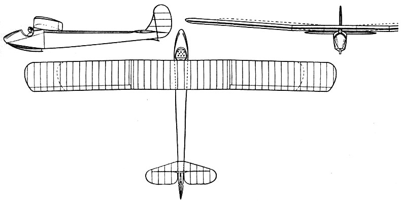
Both had almost rectangular, two-spar, wooden structured, two piece wings with fabric covering everywhere except the leading edges, which were plywood covered. The Prüfling’s wing tips were more rounded and its span 500 mm (19.7 in) greater. They both had simple ailerons reaching to the tips, where they were cropped, though the Prüfling’s were a little longer. Both had triangular tailplanes, carrying elevators that were rectangular apart for a cut-out for rudder movement, though the Prüfling’s tailplane was more strongly swept and was broader in chord.
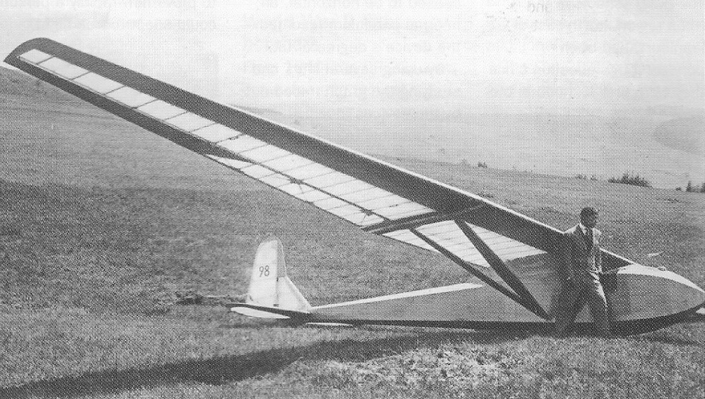
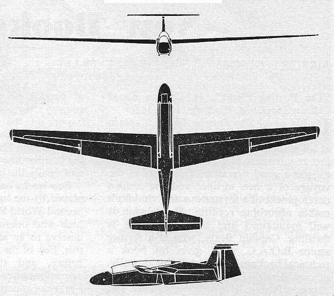
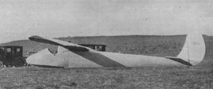
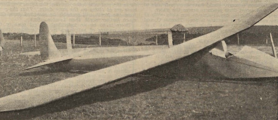
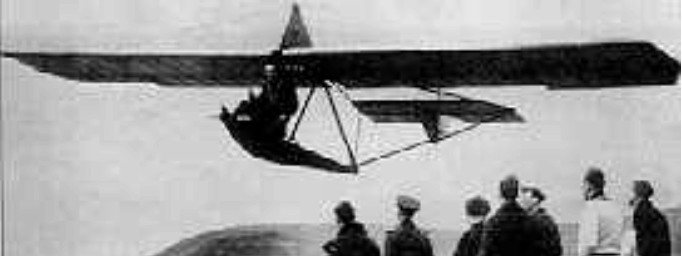
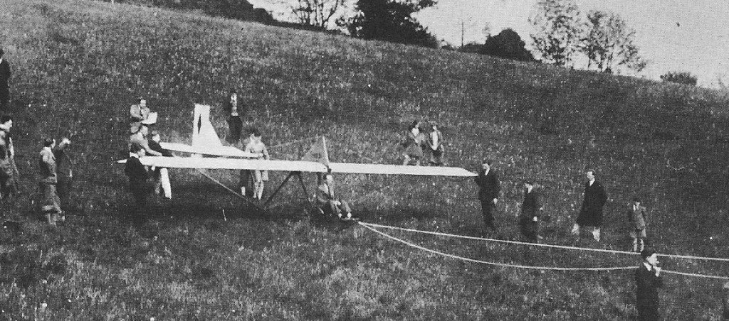
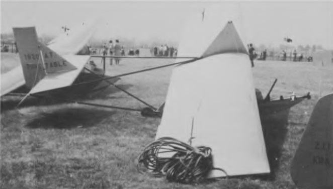
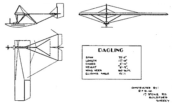
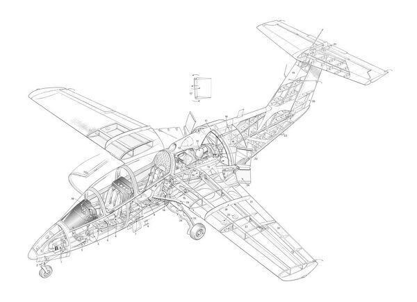
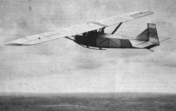
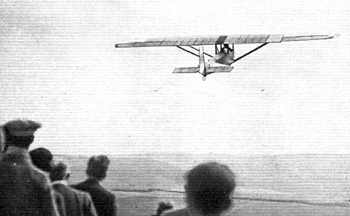
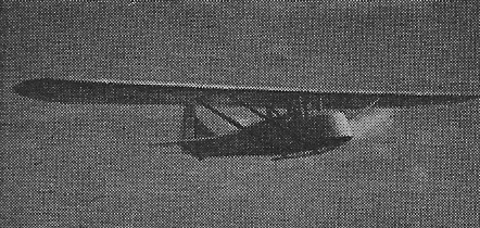
The major differences between the two were in the fuselages. The Zögling had a very simple open frame girder fuselage, the Prüfling a more conventional hexagonal cross section, wood-framed structure, ply covered forward from under the wing and fabric covered aft. The wing was supported over the fuselage with a pair of parallel lift struts on each side, bracing it at almost mid-span at the spars to the lower fuselage longerons. The open cockpit was below the wing centre section which was supported by two pairs of cabane struts to the upper fuselage longerons. The forward pair, placed just in front of the cockpit were single, upright struts but the rear ones, just behind, were each an inverted V-pair. At the centre there was a noticeable gap between the wings, bridged by a short chord wooden link. The horizontal tail was positioned on the upper longerons. with a triangular fin carrying an upright, straight edged balanced rudder which was slightly angled below the heel and extended down to the keel. The Prüfling landed on a rubber sprung skid below the whole forward, ply skinned fuselage, assisted by a very small tailskid.
It first flew in 1926 and was soon in use with the RRG related Rhön and Rossitten gliding clubs. Plans were sold and many were built inside and outside Germany.[ As examples, one was flying with the Lancashire Aero Club and another with the London Gliding Club in the early 1930s. Despite such success, the Prüfling was something of a disappointment as a secondary training aircraft, for its performance was not much better than typical primaries. Its handling was also not good, with a lack of inherent stability. Lippisch returned to the design of secondary gliders four years later, after exploring tailless types, resulting in the RRG Falke.
A Prüfling was the first glider used by the United States Navy. A single German-made aircraft was purchased from a U.S. civil glider school, assigned serial number A8546, and used for airship launch tests; the first such launch was made from USS Los Angeles (ZR-3) on 31 January 1930. The Prüfling was never assigned a formal U.S. military aircraft designation.
Wingspan: 10.50 m (34 ft 5 in)
Wing area: 15.24 sq.m (164.0 sq ft)
Length: 5.484 m (18 ft 0 in)
Aspect ratio: 7.23
Empty weight: 105 kg (231 lb)
Gross weight: 195 kg (430 lb)
Wing loading: 12.8 kg/m2 (2.6 lb/sq ft)
Capacity: One
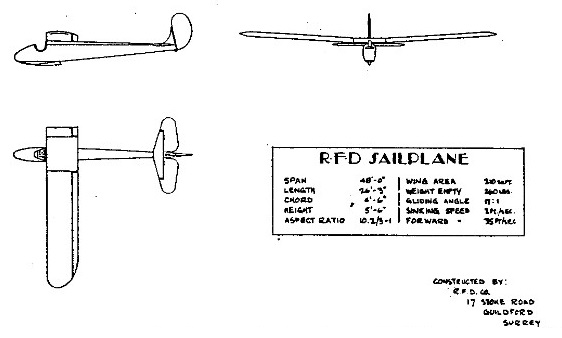
1938 Proefling
Wingspan: 42 ft
Length: 19.5 ft
Wing area: 230 sq.ft
Aspect ratio: 7.7
Empty weight: 320 lb
Gross weight: 500 lb
Mn sink: 3 ft/sec
Glide ratio: 15-1