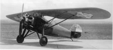
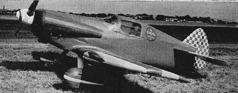
The Rogozarski PVT (Рогожарски ПВТ in Serbian, translated as Rogozarski PWT in German and as Rogojarsky PVT in some older English sources) was a single-engined, two-seat parasol winged aircraft designed as an advanced and fighter trainer in Yugoslavia before World War II.
In about 1933 the Rogozarski team of Rudolf Fizir, Sima Milutinović, Kosta Sivčev and Adem Biščević designed the PVT, a training aircraft with tandem open cockpits in an oval wooden monocoque fuselage. Its wooden, canvas covered wings were swept and parasol mounted well above the fuselage with pairs of lift struts to the lower fuselage and a central inverted V cabane. They carried long narrow chord ailerons, with prominent spades well clear of the upper surfaces
Sixty-one were built between 1935 and 1941, serving with the Yugoslav Royal Air Force until the fall of Yugoslavia in 1941. After that, some PVTs were used by the newly formed Croatian Air Force, sometimes as ground attack aircraft.
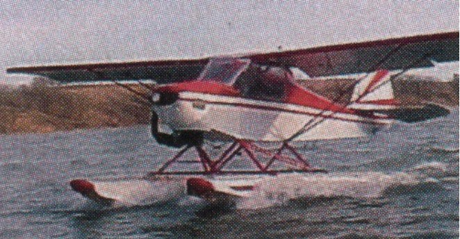
One PVT was converted to a PVT-H interim seaplane trainer. Three new PVT-H were built in 1937.
Engine: 1 × Gnôme-Rhône 7K, 310 kW (420 hp) Wingspan: 11.20 m (36 ft 9 in) Wing area: 22.1 sq.m (238 sq ft) Length: 8.54 m (28 ft 0 in) Height: 2.81 m (9 ft 3 in) Empty weight: 967 kg (2,132 lb) Gross weight: 1,213 kg (2,674 lb) Maximum speed: 240 km/h (150 mph; 130 kn) at sea level Service ceiling: 7,000 m (22,966 ft) Rate of climb: 6.54 m/s (1,287 ft/min) to 2,000 m (6,562 ft) Crew: 2
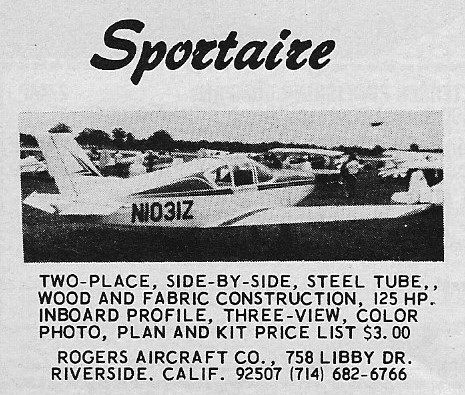
This two-place, low-wing monoplane stands on tricycle gear and is propelled by a Lycoming 125-hp engine. Building materials include tubular steel, wood and fabric.
Feb 74
Gross Wt. 1600 lb Empty Wt. 984 lb Fuel capacity 22 USG Wingspan 26’4” Length 20’6” Top speed 160 mph Cruise 150 mph Stall 55 mph Climb rate 1000 fpm Takeoff run 750 ft Landing roll 500 ft Range 400 sm
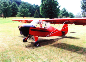
The LSA Ridge Runner is of simple construction. Build time is 275-375 hours, depending on shop set up and experience. A Speed wing was available for all models.
Ridge Runner II is not a full two place. It has a small jump seat or cargo area.
Ridge Runner III
The Model III has dual tandem seating and features a 1600 fpm climb with a Rotax 503, stalls @ 26-28 mph with full flaps, and has an 80 mph cruise.
Ridge Runner Ultralight Engine: Rotax 277, 28hp Hp range: 28-75 Wing Span: 26.20 ft Wing Chord: 46 in Wing Area: 99.40 sq. ft Length: 17 ft Height: 5.17 ft Width Folded: 8 ft Est. Empty Weight: 250lbs Gross Weight: 500lbs Est. Useful Load: 250lbs Fuel Capacity: 5 USgal Range: 175 miles Rate of Climb: 800 fpm Cruise Speed: 58 mph Stall Speed: 24 mph Takeoff Roll W/flaps: 50 ft Landing Ground roll: 50 ft Length Folded: 20 ft Gear Width: 4.66 ft Cabin Width: 24 in Seats: 1
Ridge Runner II Engine: Rotax 503, 52hp Hp range: 40-100 Wing Span: 26.20 ft Wing Chord: 46 in Wing Area: 99.40 sq. ft Length: 17 ft Height: 5.17 ft Est. Empty Weight: 350lbs Gross Weight: 900lbs Est. Useful Load: 550lbs Fuel Capacity: 5 USgal Range: 150 miles Rate of Climb: 1400 fpm Cruise Speed: 90 mph Stall Speed: 29 mph Takeoff Roll W/flaps: 100 ft Landing Ground roll: 75 ft Width Folded: 8 ft Length Folded: 20 ft Gear Width: 4.66 ft Cabin Width: 24 in
Ridge Runner III Est. Empty Weight: 360lbs Gross Weight: 900lbs Est. Useful Load: 540lbs Wing Span: 26.20 ft Wing Chord: 46 in Wing Area: 99.40 sq. ft Length: 17 ft Height: 5.17 ft Width Folded: 8 ft Length Folded: 20 ft Gear Width: 4.66 ft Cabin Width: 29″ Fuel Capacity: 10 USgal Range: 275 miles Rate of Climb: 1600 fpm Cruise Speed: 90 mph Stall Speed: 26-28 mph Takeoff Roll W/flaps: 40-75 ft Landing Ground roll: 50-100 ft
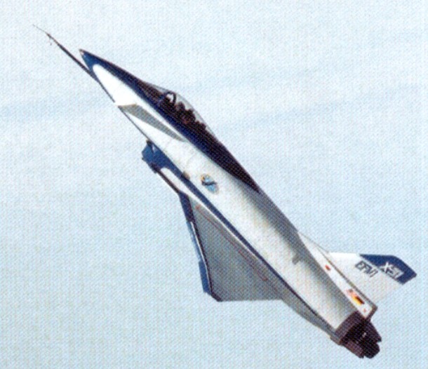
The X 31 began as an Enhanced Fighter Manoeuvrability (EFM) demonstrator at NASA’s Dryden Flight Research Center at Edwards AFB. Designed to break the “stall barrier,” allowing it to flight at angles of attack which would typically cause an aircraft to stall with a complete loss of control, the X-31 employs thrust vectoring paddles that are located in the jet exhaust and small computer-controlled canards to help keep the aircraft stable at high attack angles. It incorporates an unusual delta wing design and three thrust vectoring paddles made of graphite epoxy and located on the aircraft’s aft fuselage. These direct the engine exhaust to provide control in pitch (up and down) and yaw (right and left) thereby increasing the aircraft’s manoeuvrability. In addition, the X 31 is configured with movable forward canards, wing control surfaces and fixed aft strakes. Coupled with advanced flight control systems, the result confers a significant advantage over conventional fighters in a close in combat situation.
The X 31 is the first co operative international X plane. At Dryden, the International Test Organization (ITO) expanded the flight test envelope. The ITO, managed by the Advanced Research Project Agency (ARPA), includes NASA, the US Navy, the US Air Force, Rockwell Aerospace, the Federal Republic of Germany and Deutsche Aerospace, formerly Messerschmitt Bolkow-Blohm.
To reduce costs, several parts of existing aircraft were used in the X 31. Canopy, ejection seat and control stick were taken from an F/A 18 while several parts of the landing gear and rudder are from an F 16. Brakes and wheels were provided by Cessna and are the same as those used on the Cessna Citation. Piloted by Rockwell chief test pilot Ken Dyson, the first aircraft, serial 164584, flew from Air Force Plant 42, Palmdale, Calif, on October 11, 1990. The second aircraft, 164585, made its first flight on January 19, 1991, with Deutsche Aerospace chief test pilot Dietrich Seeck at the controls. Powered by a single General Electric P404 GE 400 turbofan engine, known to be tolerant in disturbed air and capable to produce 16,000 lb of thrust with afterburner, the maximum speed achieved by the X 31 is Mach 1.28. Controlled flight at 70o angle of attack was accomplished at Dryden on November 6, 1992. On April 29, 1993, the X 31 successfully executed a rapid minimum radius, 180o turn using a post stall manoeuvre, flying well beyond the aerodynamic limits of any conventional aircraft. Later that summer, the first simulated dog-fights were performed against a NASA F/A-18 Hornet. This resulted in 63 victories for the X-31.
The first X-31 was lost in an accident on January 19, 1995, on its 292nd flight. Due to miscommunication between pilot and air traffic control and a missing pitot tube heating system the German pilot, Karl Heinz Lang, had to eject from his uncontrollable aircraft at 18,000ft. The aircraft crashed near Edwards AFB.
The second X-31 completed the 580th and last flight of its original research program on 13 May 1995 and was placed in storage.
In February 1998, the participating contractors started VECTOR Risk Reduction and Requirements Definition. The aircraft was shipped to NAS Patuxent River in April 2000, where it was largely rebuilt for the Vector (Vectoring Extremely Short Take-Off and Landing Control Tailless Operation Research) program.
VECTOR stands for Vectoring Extremely Short Take-Off and Landing Control and Tailless Operational Research and is being used to research extremely short take off and landing capabilities and also the aerodynamic characteristics of tailless flight using integrated thrust vector control. Three technology areas are involved: Extremely Short Take Off and Landing (ESTOL) using thrust vectoring control
Flush Air Data System (FADS)
Tailless/reduced vertical tail configurations
This incorporated a new flight control software system was installed together with an auto throttle system, a belly mounted video camera and components of inertial navigation and global positioning systems. The revised aircraft made its first flight for Vector on 24 February 2001. After two months of basic flight testing, the aircraft began a year of upgrading and ground testing to perform ESTOL landings to a “virtual runway” at 5,000 feet. The X-31 took to the air again on 17 May 2002.
In these flights the aircraft flew thrust vectored, high precision ESTOL landings at reduced speeds and at high angles of attack.
To perform the automated approach, the pilot must fly into an invisible engagement box in the sky, then activate the ESTOL mode. Once successfully engaged, the pilot is not in control but is able to override the approach at any point. A video camera under the belly of the aircraft will allow the pilot to view the runway prior to landing because a pilot loses sight at anything above 15 degree angle of attack, so during final approach the aircraft will be controlled by autopilot. Coming in with its nose pointed high above the horizon, the first part of the aircraft to touch the runway would be the engine nozzle and not the landing gear. To prevent such an event, the X 31 performs [an automatic] derotation manoeuvre when the tail is just two feet above the runway, dropping onto its main landing gear. Timing of this manoeuvre is crucial; if the aircraft derotates early and drops too far, the landing gear could fail; if the aircraft derotates too late or too low, the tail could strike the runway. The aircraft is guided during approach by an Integrity Beacon Landing System (IBLS) which uses differential GPS data together with ground-based beacons to determine the aircraft’s position ensuring accurate positioning within two centimetres.
After 51 flights, the X 31 completed its first test phase on March 22, 2003, with two supersonic flights focussing on FADS performance. Pilot Knoptel reached speeds of Mach 1.06 and 1.18, in full afterburner at 39,000ft. While supersonic, he induced combinations of angle of attack and sideslip to tax the FADS. By night, engineers had processed the data and were able to confirm that the FADS was performing as desired throughout the flight regime.
This cleared the way for the final phase of flight tests that began in early April 2003 and ended on April 29 when the last ESTOL landing was performed by Maj Allee following a week of successful testing the world’s first fully automated, thrust vectoring landings. This landing was performed with an angle of attack of 24 o and a speed of 121kt, a reduction of 31% compared with the normal landing speed of 175kt. The X 31 requires a normal runway length of 8,000ft to stop after a conventional landing, but after the final ESTOL landing, the aircraft needed just 1,700ft to slow down enough to turn around on the runway.
Sponsors: DARPA, USN, German MoD Fastest Flight: Mach 1.28 (900 mph) Highest Flight: 40,000 feet (approx)
X 31 Powerplant: One General Electric P404¬GE 400 turbofan, 16,0001b thrust with afterburner Span; 23,83ft (7.3m) Length, 43.33ft (12.8m) Take off weight, 16,1001b (7,303kg) Max achieved speed, Mach 1,28 at 35,000ft Max achieved altitude, 40,000ft (12,200m)
X-31A Powerplant: one 10,600-lb (4808-kg) thrust General Electric F404-GE-400 non-afterburning turbofan Wingspan 23 ft 10 in (7.26 m) Length 43 ft 4 in (13.21 m) excluding probe Height 14 ft 7 in (4.44 m) Wing area 226.3 sq ft (21.02 sq.m) Canard foreplane area 23.6 sq ft (2.19 sq.m) Maximum speed 597 mph (961 km/h) or Mach 0.9 at 35,000 ft (10,670 m) Empty weight 10,212 lb (4632 kg) Maximum take-off 13,968 lb (6335 kg) Crew: 1
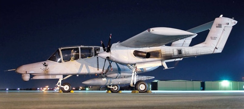
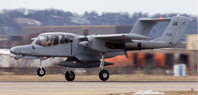
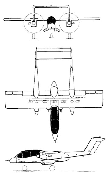
To meet a US Navy requirement for a light armed recon¬naissance aircraft, North American Rockwell produced their NA-300 design submission for the OV 10A Bronco. A contract for seven YOV-10A prototypes was placed in 1964, the first of them flying on 16 July 1965.
With a two-seat fuselage nacelle mounting a high-set monoplane wing, the aircraft had twin tailbooms extending aft from the nacelles of the two turboprop engines, each with a fin and rudder, and interconnected by a tailplane/elevator assembly. The main units of the tricycle landing gear retracted into the engine nacelles.
Six of the prototypes were powered by 447kW Garrett T76-G-6/8 engines, but had one Pratt & Whitney YT74-CP-8/10 turboprops for comparative evaluation.
The OV-10A Bronco production version had a 3.05m increase in wing span and more powerful T76-G-10/12 engines, the first flown on 6 August 1967, and 114 were built for the US Marine Corps.
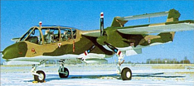
These were followed by 157 similar OV-10As for the US Air Force, these entering operational service in Vietnam in 1968. Under the US ‘Pave Nail’ programme, 15 were provided with special equipment for the location and illumination of targets by night. Other versions have included six OV-10B aircraft supplied to Germany as target tugs, followed by 18 turbojet-boosted OV-10B(Z) aircraft for the same role. Versions similar to the OV-10A have been supplied to Indonesia (16), Thailand (40) and Venezuela (16), under the respective designations OV-10F, OV-10C and OV-10E, and six US OV-10As have been transferred to the Royal Moroccan air force.
Two OV-10As were modified under a US Navy contract of 1970 to YOV-10D NOGS (Night Observation/Gunship System) aircraft to provide the US Marines with advanced night operational capability. Since evaluation of these aircraft, 17 US Marine Corps OV-10As have been converted to OV-10D NOS (Night Observation Surveillance) configuration, now equipped with a FLIR (forward-looking infra-red) turret in the nose linked to an underfuselage 20mm cannon turret, and a laser target illuminator.
Production of the Bronco for the USMC, USAF, and four export customers was completed in 1980.
Able to carry a maximum weapon load of 3,600 lb (1,633 kg), the Bronco has proved valuable for Forward Air Control (FAC) operations in South East Asia.
Of the seven prototype North American Rockwell OV 10 Broncos built, No.3 on the line was heavily modified and was the only short-wing example of the aircraft ever built. YOV 10A 152881 (N718NA) has a wingspan of only 32ft (9.75m), whereas standard production aircraft had 40ft (12m) of wing. From 1966 to 1972 the aircraft was used as a demonstration airframe and was used to take Admirals, Generals and Congressmen for flights to extol the virtues of the twin engined observation and forward air controller design. The Bronco was also assigned to train new pilots on the gunnery ranges, using its machine guns and rockets. During the spring of 1972 it was assigned to NASA under the Department of the Army, for STOL flight testing. This was carried out at the Ames Flight Test Center in California, with the aircraft being allocated a civilian registration.
During its time at Ames, the Bronco was heavily modified, the aircraft’s Garrett T 76 turboprops were removed and replaced by Lycoming T 54s. Three blade 7ft (2.1m) Hamilton Standard propellers were replaced with 10ft (3m) four bladed Curtiss Electric composite propellers, and the engines were interconnected by a single solid shaft in the leading edge of the wing. With this system in operation, the aircraft flew at 47 knots and NASA was working toward getting the minimum speed down to 30 knots. The Bronco became unstable, and the programme was stopped. The aircraft was with NASA until it was sold to the Detroit Institute of Aeronautics in 1979.
OV-10A Engines: 2 x Garrett AiResearch T76-G-416/417, 715 shp Wing span: 40 ft 0 in (12.19 m) Wing area: 290.951 sqft / 27.03 sq.m Length: 41 ft 7 in (12.67 m) Height: 15 ft 2 in (4.62 m) Max TO wt: 14,446 lb (6563 kg) Weight empty: 6892.8 lb / 3126.0 kg Max level speed: 281 mph (452 kph) Cruising speed: 168 kts / 312 km/h Service ceiling : 27001 ft / 8230 m Maximum range: 1199 nm / 2220 km Range (max. weight): 410 nm / 760 km Crew: 2 Armament: 4x MG 7,62mm M60C/500rds., 1633kg ext. 5pts.
OV-10B Engines: 2 x Garrett T76-G-418
OV-10D Engines: 2 x Garrett T76-G-420/421 turbo-prop, 776kW / 1040 shp Max take-off weight: 6552 kg / 14445 lb Empty weight: 3127 kg / 6894 lb Wingspan: 12.19 m / 39 ft 12 in Length: 13.41 m / 43 ft 12 in Height: 4.62 m / 15 ft 2 in Wing area: 27.03 sq.m / 290.95 sq ft Ceiling: 9145 m / 30000 ft Range w/max.payload: 740 km / 460 miles Bombload: 2000kg Crew: 2
The Rockwell B-1 resulted from a November 1969 requirement for a medium-altitude with dash capability of Mach 2.2+ for the high-speed delivery of free-fall and stand-off nuclear weapons. Submissions were received from several companies, Rockwell’s design being selected in 1970 as the B-1A. The full-scale design and development programme for the initial production version was soon under way. The initial model was a complex and highly advanced variable-geometry type with General Electric F101 turbofans and fully variable inlets for maximum capability in all elements of the flight envelope.
The first of four prototypes (71-40158) of the Rockwell International B-1 four-turbofan strategic heavy bomber made its maiden flight on 23 December 1974; designed to meet USAF Strategic Air Command’s Advanced Manned Strategic Aircraft (AMSA) requirement, it incorporated variable geometry wings (maximum sweep of 67 degrees), accommodated a four-man crew and had an estimated maximum speed of Mach 2 at altitude.
In June 1977 President Carter decided to scrap the programme in favour of cruise missile development although flight trials with the B-1A aircraft were to be continued for research purposes, the flight testing continued through 1981 with the four prototypes.
Then with the inauguration of President Reagan matters began to look up again, the new administration deciding during October 1981 to procure 100 examples of a much revised B-1B version in the low-level penetration role for high-subsonic delivery of free-fall and stand-off weapons. The B-lB was.therefore a straightforward but nonetheless major adaptation of the B-1A optimized for the low-level transonic role with fixed inlets and revised nacelles (reducing maximum speed to Mach 1.25). But it did have a strengthened airframe and landing gear for operation at higher weights with nuclear and conventional weapons over very long ranges. Other changes were concerned with reduction of the type’s already low radar signature, S-shaped ducts with streamwise baffles being adopted to shield the face of the engine compressors and radar absorbent materials being installed in sensitive areas to reduce electromagnetic reflectivity. The second and fourth B-lAs were used from March 1983 to flight-test features of the B-1B, which first flew in September 1984 with the advanced offensive and defensive electronic systems.
In conjunction with the USAF, Edwards AFB, ASA Dryden Flight Research Center carried out two six-hour flights of the B-1, with the first taking place on 25 March 1981. B-1 number 3, part of the USAF/Rockwell joint test force Bomber Penetration Evaluation was utilised for the two flights. The two supersonic flights evaluated the Structural Mode Control System.
The first production B-1B flew on October 18, 1984, some five months ahead of schedule. Two B-1A development aircraft had previously been converted to B-1B standard, the first flying in B-1B form in March 1983. Production deliveries began in July 1985, to replace B-52Hs in the penetration role, and will continue until 1988.
The ninth B-1B was the first to be fitted with a moveable bulkhead in the forward weapons bay, enabling it to carry eight AGM-86 air-launched cruise missiles (ALCM), short-range attack missiles (Sram), and extra fuel tanks internally. Maximum ALCM loading is eight missiles internally and 14 externally on eight underfuselage hardpoints.
Initial Operational Capability was first achieved on 1 October 1986.
In January 1987 a B-1B successfully launched a short-range-attack missile for the first time, while in April an aircraft from the 96th Bomb Wing at Dyess AFB, Texas, completed a 2l hr 40min mission including five in-flight refuellings (to maintain a high aircraft weight), covering a distance of 15,145km (8,175 nm).
The final B-1B was delivered 2 May 1988.
In 1989, when Neil Armstrong became chairman of AIL Systems Inc., he was invited to fly the B-1 bomber. He later flew the B-1 again for the first flights television series.
The B-1B Lancer were modified and aircrews were trained for the use of conventional weapons, including stand-off and laser guided weapons, and did flew combat missions during Operation Desert Fox.
Also in 1999 the B-1s flew bombing missions using conventional weapons against Yugoslavia as part of Operation Allied Force.
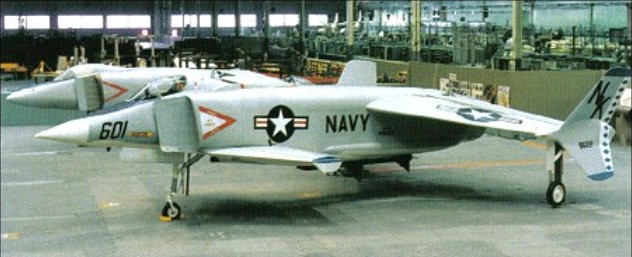
Rockwell became responsible in 1972 for development of the US Navy’s XFV-12A V/STOL Fighter/Attack Technology Prototype programme.
Basically a single-seat all-weather V/STOL fighter/ attack aircraft, the XFV-12A made use of an augmentor wing concept in which the efflux of its single Pratt & Whitney F401-PW-400 afterburning turbofan engine could be diverted to nozzles in the wings and foreplanes for V/STOL operations.
An ejector-flap system was incorporated in the design of each wing and foreplane, in which ambient air was mixed with turbine efflux in a ratio of 7:1 to provide the essential jet-lift for vertical operations and, when the flaps are raised or lowered progressively, for transition from vertical to horizontal flight and vice versa.
The main landing gear, canopy and other cockpit parts came from an A-4 Skyhawk. The main wing box and parts of the inlets were from an F-4 Phantom.
The XFV-12 did get off the ground – and was tested in a tethered mode, but the programme proved a disappointment and failed to provide an alternative to the Harrier.
Engine: 1 x 133.4kN Pratt & Whitney F401-PW-400 turbofan Max take-off weight: 11000 kg / 24251 lb Wingspan: 8.69 m / 29 ft 6 in Length: 13.35 m / 44 ft 10 in Height: 3.15 m / 10 ft 4 in
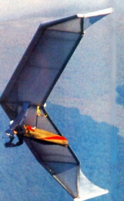
The Flair was a design developed by Günter Rochelt in 1987. Featured on the cover of ‘Drachenflieger’ magazine in November 1987. It was first conceived in 1984, but took some time to develop, with work on the fiberglass – Carbon – Kevlar airframe begun in Spring 1987. After a few test flights, in which the performance was confirmed but the rudders were found to be somewhat ineffectual, Günter decided not to put the Flair into production, concluding that he could improve performance further with some changes to the design (which led to the Flair 30, whose design goal was to reach a 30:1 glide ratio in a foot-launched aircraft.)
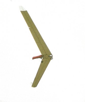
The Flair 30 was a follow-up to the Flair design and first flew in 1990. The pilot could launch by foot, then lay prone in a special harness, and finally land on a skid. After extensive test flights, including more than 50 hours logged by test pilot Knut Von Hentig, the prototype was destroyed in a crash at a sailplane club, when the sailplane pilot flying it dove into the ground at high speed from less than 100 m. Control reversal was suspected but unproved.
Flair 30
The test pilot felt the glide ratio and sink rate was quite poor, worse actually than modern flex wings
Flair Wing area: 14.5 m² Wing span: 11.47 m Aspect ratio: 9 Maximum pilot weight: 165 kg Max glide ratio (L/H): 17 Max glide ratio speed: 45 km/h Minimum sink rate: 0.65 m/s Nose angle: 147°
Flair 30 Wing area: 11 m² Wing span: 12 m Aspect ratio: 14 Profile: CM-140-K47 Hang glider weight: 33 kg Maximum pilot weight: 90 kg Minimum speed: 30 km/h Maximum speed: 150 km/h Max glide ratio (L/H): 30 Max glide ratio speed: 65 km/h Minimum sink rate: 0.72 m/s Packed length: 6.6 m Nose angle: 160°
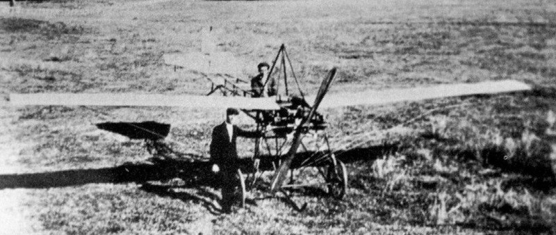
Azor D. Robbins built the flat 4-cylinder engine in 1911 and, with Alex Porter in 1913, went on to construct this monoplane in Australia. Made a few short flights during the summer of 1913, then was damaged during a landing. Stored in a garage, it was lost in a fire in 1914 or 1915.
Designed for aerobatics, the Robinson MDR-1 Special is all metal and uses cut-down Luscombe wing panels. Many other Luscombe parts were used and it is powered by a 115 hp Lycoming engine.