Ross R-2

The R-2 was quite similar to the RS-1 but the gull wing had a 48 ft. span and an all-moving tail was used. It made the first wave flight I the U.S. on Oct. 25, 1938, at White Mountain, New Hampshire.

Wingspan: 46 ft
Length: 20.5 ft
Wing area: 125 sq.ft
Aspect ratio: 17
Empty weight: 280 lb
Gross weight: 470 lb
Min sink: 2.5 f/sec
Glide ratio: 23-1

Rose Renegade / Mach-Buster

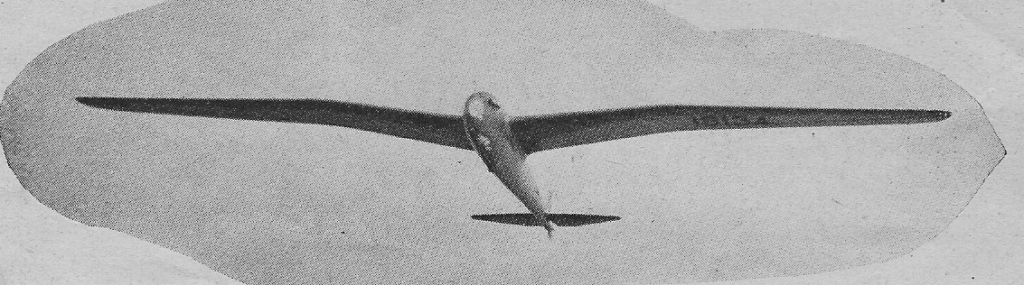
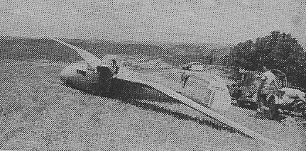
In 1999 David Rose bought Mach-Buster, a partially completed airplane whose design was based on high-speed aerodynamic research that had been performed at NASA Ames Research Center at Moffet Field, California.

After considerable time and effort to finish Mach-Buster, David, with Skip Holm and John Penney determined the design was not suitable for flight testing and abandoned the project. His mission is to step into an unlimited of his own design and compete.

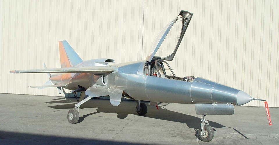
The team then started from scratch and started developing a new design using computer modelling, analysis, and simulation methods. After mathematical modelling demonstrated their new technology would work, the team started cutting metal and welding.

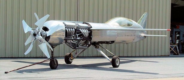
Crew chief Jerry Baer and machinist Eric Hereth started by jigging up a fuselage that uses 1-3/8” diameter Chrome-Moly tube, TIG welded together. The highly triangulated fuselage weighs 180 pounds bare. They fabricated a simple landing gear system that uses an Oildyne hydraulic power unit. The nose and main gear fold forward as they stow. This makes emergency gear extensions foolproof as the air stream pulls them down and locked in the event of a hydraulic system failure. Retraction is a little less than two seconds.

The new design has an aluminum skin. The team fabricated aluminum bulkheads that bolt to the fuselage and create the curves that define the fuselage shape. 6061-T6 panels were cut and shaped to fit in sections. After trial-fitting with Cleco fasteners, the panels were riveted permanently in place, or screwed down in case access to the interior was needed.

The all-carbon fiber wings (David has two sets). He has a wing that was designed for high-speed flight. Additionally, he has a flapped aluminium wing that is specially built to provide optimum performance while banking around the course at Reno. Both wings are bolt-on, and their incidence to the fuselage can be optimized.

The tail feathers were designed to balance the needs of slow flight while reducing drag at speed. The horizontal stabilizer was mounted low on the tail cone to avoid the effects of wing turbulence when the aircraft is at high angles of attack, such as during the landing phase.

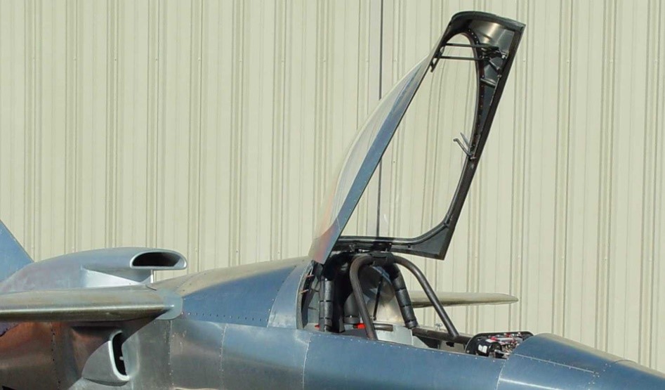
David initially brought home an F-16 canopy, but after a trial fit realized that it would be way too large for this fuselage. Fellow Reno racer Darryl Greenamyer paid a visit to the Renegade hanger one day and offered David one of his canopies that had been designed for his Unlimited racer, Shockwave. The new canopy still needed to be cut down, but fit perfectly after the trim job.

Renegade is not an aerobatic airplane, but high load banking and the occasional roll are necessary, so the team designed and built Renegade to handle positive 8 g’s and negative 4 g’s. The airframe loads were computer-analyzed using finite element analysis (FEA). Additionally, the wings were loaded using sand bags. They passed the test. Renegade’s empty weight came in at 2,300 pounds, with the gross weight topping out at 2,985 pounds.

The powerplant is a Pro-Stock style DRCE V-8 with a cast-iron block and large-valve aluminum heads. It sports a forged crankshaft, pistons, and connecting rods. The normally aspirated engine displaces 550 cubic inches and has a 13:1 compression ratio. A Peterson dry-sump system keeps the engine lubricated, while the dry-sump oil pan allows the engine to be located low in the fuselage.

The intake manifold is a Kinsler unit with a computer-controlled, Electromotive integrated fuel injection/ignition system. The water pump and mechanical fuel pumps are part of an accessory case that is cam-driven. A lightweight starter spins an 8-pound steel flywheel, and a fluid damper controls crank torsional vibration. The big V-8 is liquid-cooled; fresh air enters through side scoops mounted underneath each wing. Inside, twin radiators are mounted in a “V” configuration.

The engine is capable of a 7800-rpm redline, but David set the Electromotive’s rev limiter to 6800 rpm. At this rpm, the engine will produce 1,230 hp and 950 feet/pound of torque. At max horsepower, the cylinder’s “brake mean effective pressure” is 261 pounds per square inch.

A splined coupler drives a 5-inch diameter, 51-inch long, carbon-fiber drive shaft originally designed for offshore boat racing. The drive shaft terminates at a bearing carrier where the pusher prop is mounted. The prop is a four-blade design, custom made of carbon-fiber, and has a 48-inch diameter. The pitch is ground-adjustable. The prop underwent extensive load and vibration testing under the auspices of vibration specialist Dr. Tom Trozera, who safely spin-tested the prop to 18000 rpm. This resulted in a 2.6:1 safety factor above the prop’s redline of 6800 rpm. With a 35-degree blade angle (79-inch pitch) optimized for flight tests less than 300 mph, the prop efficiency should be about 74 percent, producing 1,560 pounds of thrust and a tip speed of Mach 1.33.

David and the team have calculated Renegade’s flight performance and the results should make for an easy flier. They estimate the take-off roll to be about 2,000 feet, with rotation coming at 100 Kts. Once airborne, the climb should be 3500+ feet per minute. Leveling out, Renegade should easily accelerate to 300 Kts.

Renegade is designed to race at Reno and should be able to achieve 430 Kts (495 mph) once all systems are fine-tuned. Approaches are made with full flaps at 135 Kts. Once the runway is made, Renegade should touch down at 95 Kts. A speed brake is deployed to help scrub off speed until the brakes take over. Renegade carries 85 gallons of fuel as this V-8 burns 105 gallons per hour. Never intended to be a cross-country flier, Renegade can fly at race speeds for 45 minutes. It was designed to be trailerable—the wing can be detached in less than 30 minutes.

Renegade meets all the Reno National Air Races Unlimited class rules. Because Renegade was not seen as a traditional Unlimited racer, Reno Air Racing Association officials had concerns but felt that if complete flight tests were successful, David would be invited to attend Reno’s Pylon Racing School.

Their proof of concept, Renegade, was built in less than a year.

Engine: Olds DRCE V-8 550 cui, 1,230 hp
Torque: 950
Engine Redline: 6800 rpm
Wing Span: 17 ft
Wing Area: 70 sq.ft
Empty Weight: 2,300 lbs
Gross Weight: 2,985 lbs
Fuel Capacity: 85 USgal
Wing Loading: 42.6 psf
Fuel Burn (full throttle): 105 gph
Top Speed (est.): 495 mph
Rate of Climb (est.): 3,500+ fpm
Stall Speed (est.): 103 mph
Seats: 1

Rose RP-4

David Rose built the overpowered RP-4 for speed. The experimental counter-rotating propellers, inspired by a NASA project, run at 4800 rpm. Rose can connect both propellers directly to their engines without heavy reduction gearing. The props can change pitch for maximum efficiency at any speed. “It’s a drag-racer frame with skin on it to keep the wind out,” says Jerry Baer, a former pilot who helped Rose build RP-4.

Intended to compete in the Unlimited Class at the Reno Air Races, work began on the David Rose RP-4 project in 2005. Designed by Mr. Rose and built primarily be Eric Hereth, both of San Diego, at slightly over 4,600 pounds, 100 more than the minimum allowable, it was estimated that the racer would tour the course at upwards of 600 miles per hour, at least 100 mph faster than the then record holder.

Power is provided by two 600 cubic inch displacement V-8 engines designed originally for drag racing and, in that configuration, each is capable of producing as much as 2,500 horsepower (hp). Detuned to approximately 1200 hp. each, the engines were expected to withstand the rigors of running at full throttle for eight minutes, the time required to complete each heat at Stead Field in Reno.

The engines are mounted in tandem, each with its own independent systems, and each driving its own propeller. The engines are pressure-fed by two Pro-Charger F3-R centrifugal type superchargers with refrigerated intercoolers. The induction system is custom made from the 6” diameter throttle plate, to the attachment at the cylinder heads. The fuel is delivered by an electronic fuel injection system, also custom made for this application. Two-inch diameter stainless steel headers converge into collectors at the bottom of the fuselage exiting rearward and providing additional thrust in the process.

The contra-rotating propellers are reflective of those used in a ducted-fan experiment in the 1960s. Very efficient, but noisy, they split the job of delivering thrust and also cancel the negative torque reactions resulting from the P-factor, making such a high-power aircraft of small dimensions much more easily controlled.

The racer employs a unique engine cooling system. To eliminate any unnecessary parasitic drag on the fuselage, all scoops typically found in this type application are absent. Water from the engine cooling jackets is directed through the wings in parallel tubing, while the wings themselves are filled with water. Heat is transferred from the tubing into the water and heat from the water is transferred overboard through the wing skins. The wing will hold about 50 gallons of water adding about 400 pounds to the weight of the aircraft, which will help it reach the unlimited class weight limit.

All custom crafted by Eric Hereth, the fuselage is 31 inches in diameter with the canopy protruding 12 inches above its top line. It is constructed of welded chromoly tubing, stressed for over 10 g’s and covered in aluminum sheeting. Spinner to tail the aircraft measures 28 feet, with a wingspan of 20 feet and a cord length of four feet at the root. Wing area is 58 square feet, resulting in a wing loading of nearly 100 pounds per square foot.

A change in the rules instituted by the Reno Air Racing Association (RARA) prevented the racer from completing in the unlimited category, and as a result, work on the nearly completed aircraft was halted in 2012.

Romano Ro 110

Designed for an October 1934 specification calling for a three-seat fighter to serve as an aerial command post for single-seat fighters, the R-110 was flown for the first time on 30 March 1938.

Of mixed construction, with plywood-covered wooden wings and a welded steeltube fuselage, the R-110 was powered by two 450hp Renault 12 Ro 2/3 12-cylinder air-cooled engines. Armament was two fixed 20mm cannon and a single 7.5mm machine gun on a flexible mount in the aft cockpit.

The R-110 was unusual in that the pilot and aircraft commander were seated behind separate vertically- staggered stepped windscreens. The competing Potez 630 had appeared in production form before the R-110 prototype entered flight test and further development of the latter was discontinued.

Max take-off weight: 3300 kg / 7275 lb
Empty weight: 2165 kg / 4773 lb
Wingspan: 12.80 m / 42 ft 0 in
Length: 9.66 m / 32 ft 8 in
Height: 3.37 m / 11 ft 1 in
Wing area: 24.00 sq.m / 258.33 sq ft
Max. speed: 470 km/h / 292 mph
Range: 1280 km / 795 miles

Romano R-110

Romano R.16 / 160

In 1930 the Direection Générale Technique issued a programme for an aircraft to operate in the French Colonies. It was to have three Lorraine 9N Algol engines and an all-metal structure, capable of reconnaissance, observation, policing and bombing as well as medical evacuations or general transport. The Romano R.16 was one of nine prototypes built to this programme.

Despite the all-metal requirement, the Romano R16 initially flew with a wing of mixed construction which was originally built for the rather similar Romano R.6 civil passenger aircraft. It is not known if the intended wing, all-metal and expected to be lighter, ever replaced it. On each side the high wing was in two parts, with a rectangular inner section attached to the top of the fuselage. The outer panels were straight tapered to rounded tips. The wing had two wooden box spars and spruce ribs and was entirely plywood covered. The centre section, over 40% of the span, was braced at its outer ends with a pair of parallel steel wing struts between the wing spars and the lower fuselage longerons, so that the R.16’s wing was a semi-cantilever one. High aspect ratio ailerons occupied the whole outer panel trailing edge and camber changing flaps filled those of the centre section.

The R.16 was powered by three 220 kW (300 hp) Lorraine 9N Algol nine cylinder radial engines enclosed by long chord NACA-type cowlings. One was in the nose of the fuselage and the other were mounted under the wing centre section from the forward wing struts, aided by bracing struts rising inwards to the wing root and short vertical struts to the forward spar. Long nacelles behind the outer engines tapered to the rear wing strut.

Structurally the R.16’s fuselage was built around steel tube longerons, giving it a simple rectangular cross-section. The pilots’ enclosed cabin was below and just ahead of the wing leading edge, fitted with side-by-side seating and dual controls. Behind them there was a generous cabin, accessed via a large port side door. Aft of the cabin, just behind the trailing edge was a dorsal gunner’s position. At the rear the fixed surfaces were approximately triangular and carried a balanced rudder and elevators, also balanced. Each tailplane was braced on the vertex of a V-strut from the lower fuselage. The tail surfaces were steel tube structures with fabric covering.

The colonial aircraft were expected to have to use basic or unprepared strips, so needed a robust undercarriage. The R.16 had large 1,150 mm (45 in) diameter wheels, independently mounted and fitted with brakes that could be use for steering, enclosed under large fairings. Each wheel was on a cranked steel half axle from the lower fuselage with a trailing recoil strut and a vertical oleo leg to the engine mounting.

The R.16 flew for the first time in February 1933. By May the initial development tests at Romano’s Cannes factory were complete. It then went to Villacoublay for its official tests, which were completed by early September.

The Colonial trimotor contract was awarded to the Bloch MB.120, so no more R.16s were built. The sole example appeared in the prototypes section of the French civil aircraft register as F-AKGE, with the type name Romano 160 and was used by the Commander of the 5th Aerial Region of French North Africa as his personal transport. A photograph taken at Cannes in 1937 shows that by then it had been adapted to carry passengers, the cabin now lit by long, continuous windows on each side. It also had a revised vertical tail with an unbalanced rudder.

Romano R.16
Powerplant: 3 × Lorraine 9Na Algol, 220 kW (300 hp) each
Propellers: 2-bladed Ratier
Wingspan: 21.60 m (70 ft 10 in)
Wing area: 70 m2 (750 sq ft)
Length: 13.90 m (45 ft 7 in)
Height: 4.05 m (13 ft 3 in)
Empty weight: 3,138 kg (6,918 lb)
Gross weight: 5,200 kg (11,464 lb)
Fuel capacity: 415 l (91 imp gal; 110 US gal)
Maximum speed: 230 km/h (140 mph, 120 kn) at ground level
Cruising speed: 195 km / h
Landing speed: 81 km/h (50 mph; 44 kn)
Range: 1,200 km (750 mi, 650 nmi)
Service ceiling: 2,400 m (7,880 ft) theoretical
Time to altitude: 13 min 5 sec to 3,000 m (9,800 ft)
Take-off distance: 150 m (490 ft)
Crew: Three

Romano R.15

The R.15 was a high-wing floatplane of all-metal construction built in France by Romano. The pilot and passenger were seated in an enclosed cabin. It first flew in 1933 and showed good flight characteristics, but failed to win orders from the civil aviation industry.

Powerplant: 1 × Salmson 9Aer, 56 kW (75 hp)
Wingspan: 14.45 m (47 ft 5 in)
Length: 9.06 m (29 ft 9 in)
Height: 3.47 m (11 ft 5 in)
Wing area: 26.30 m2 (283.1 sq ft)
Empty weight: 928 kg (2,046 lb)
Gross weight: 1,268 kg (2,795 lb)
Maximum speed: 186 km/h (116 mph, 100 kn)
Cruise speed: 160 km/h (99 mph, 86 kn)
Range: 500 km (310 mi, 270 nmi)
Service ceiling: 6,500 m (21,300 ft)
Crew: 2

Romano R-6

The Romano R.6 was a transport aircraft built by Romano in France in the early 1930s. It was a three engine, high wing monoplane transport of all-metal construction.

First flying on 20 December 1932, only the one was built.

A longer wing-span colonial police transport was also built as the Romano R.16.

Engines: 3 × Gnome & Rhône 7Kb, 220 kW (300 hp) each
Propellers: 2-bladed Ratier
Wingspan: 19.64 m (64 ft 5 in)
Wing area: 63.00 m2 (678.1 sq ft)
Length: 13.90 m (45 ft 7 in)
Height: 3.27 m (10 ft 9 in)
Empty weight: 3,047 kg (6,717 lb)
Gross weight: 4,473 kg (9,861 lb)
Maximum speed: 216 km/h (134 mph, 117 kn) at ground level
Range: 1,000 km (620 mi, 540 nmi)
Service ceiling: 6,850 m (22,470 ft) theoretical
Crew: Three
Capacity: 8 passengers

Romano R.5

In 1929 the French Air Ministry drew up a programme of military aircraft specifications to meet France’s needs over the next few years. One part called for a reconnaissance and observation seaplane and the R.5 was Romano’s response; at least two other manufacturers also built prototypes, though funding was not yet assured.

The Romano R.5 was an all-metal flying boat. Its parasol wing was built in three parts; its centre section mounted a 480 kW (650 hp) Hispano-Suiza 12Nbr water-cooled V-12 engine in tractor configuration on its leading edge and was braced 1,650 mm (65 in) over the fuselage by parallel pairs of struts from its outer ends to the mid-fuselage. Six short cabane struts braced it centrally. The inner and cantilever outer panels together provided a trapezoidal plan wing out to rounded tips; ailerons occupied most of the outer panels’ trailing edges. Structurally a mixture of steel and duralumin, with dural skinning, the wing was built around two spars; in the centre section these were elaborated into a trellised girder.

Its 15-metre-long (49 ft 3 in), flat-sided hull was built with of dural and with vedal, layers of dural and pure aluminium, for parts in direct contact with sea-water. The V-form underside had a single step under the wing and, further aft, a water rudder. The R.5 had a pair of Dornier-style sponsons, 6.3 m (20 ft 8 in) in span and 2.5 m (8 ft 2 in) at their broadest, mounted on the lower sides of the fuselage instead of wing mounted floats. There were plans to use these to contain retractable wheels to turn the R.5 into an amphibian.

In the nose there was a position for mooring operations, navigation equipment and a machine gun mounting. The pilots’ cabin was ahead of the propeller disc, fully enclosed and with side-by-side seats and dual controls. Behind the wing there were positions for a navigator who also operated the bomb release controls and for a radio and camera operator. Behind them was a dorsal gunner’s position, midway between the trailing edge and the tail. The fuselage became slender to the rear, where the tall fin carried a deep, rounded unbalanced rudder. The R.5’s tapered tailplane was raised out of the spray well up on the fin and supported from below with a pair of parallel struts from the upper fuselage. Its elevators were inset and unbalanced but far enough forward to only require a small central nick for rudder movement.

R-5

The Romano R.5 first flew in September 1932. Soon after, it was delivered to the Forces Aérienne de la Mer along with its competitors, the Amiot 110-S and CAMS 80. Only one was built.

Engine: 1 × Hispano-Suiza 12Nbr, 480 kW (650 hp)
Wingspan: 22.60 m (74 ft 2 in)
Wing area: 67.5 m2 (727 sq ft)
Aspect ratio: 7.6
Length: 16 m (52 ft 6 in)
Height: 4.50 m (14 ft 9 in)
Empty weight: 3051 kg
Gross weight: 4,300 kg (9,480 lb)
Maximum speed: 217 km/h (135 mph, 117 kn) at 1,500 m (4,900 ft)
Cruise: 172 kph
Range: 1,500 km (930 mi, 810 nmi)
Service ceiling: 6,700 m (22,000 ft)
Time to altitude: 6 min 5 sec to 1,500 m (4,900 ft)
Armament: two 7.5-мм Darne machine guns
Bomb load: 200 kg
Crew: Three