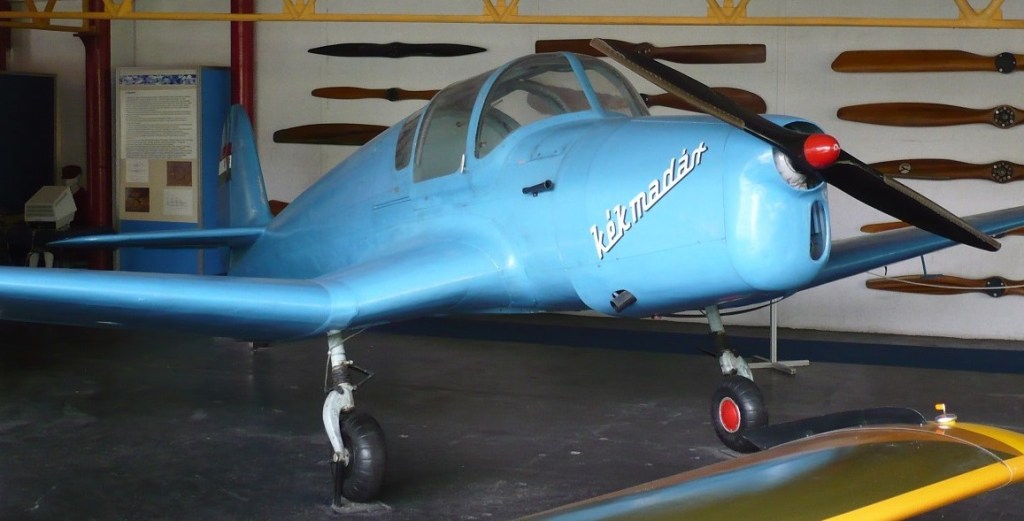
Hungary, 1948
Hungary, 1948
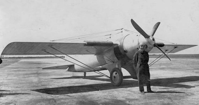
The Beaumont Cup races were to be held in Istra, but by decision of the French club (l’Aéro-Club de France) they did not take place for several reasons, one of which was the lack of participants: only 5 aircraft were registered, all of which were French. Salmson created the SB 3 aircraft (numbered “5”), which was tested by Potez test pilot Gustave Douchy.
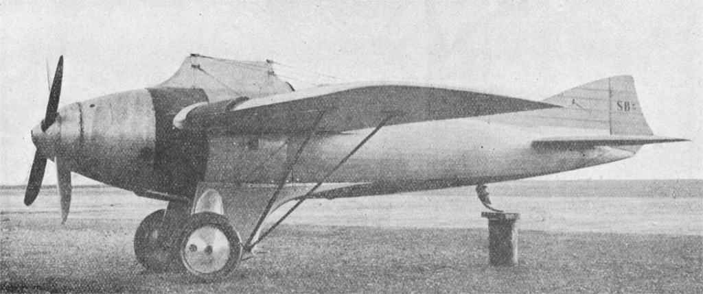
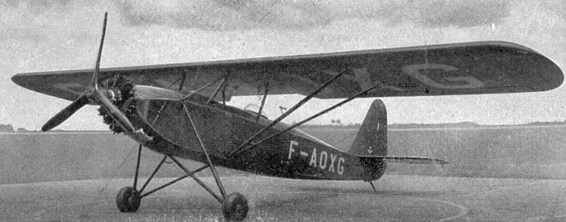
Salmson-Béchereau SB 3 originated from SB 2 and was distinguished by a rather stocky shape and a huge nose. Its wing was supported by Y-shaped struts, which relied on the oil-pneumatic shock absorbers of the chassis design Louis Bechereau, the patent for which he received July 6, 1922 (No.553710). The mechanism was also equipped with cushioning cords hidden in these struts. The 520-horsepower Salmson 18 CMb engine installed on the aircraft was supposed to be cooled with Lamblin sheet radiators located in the front edge of the wing next to the fuselage. The skin of the aircraft consisted of varnished unbleached canvas. During the tests, terribly inadequate engine cooling was detected and speed tests were restricted. It was sent to Istres in October 1923 where Loizeau, an engineer, installed several straight lines on the radiators increasing their area.
According to the Beaumont Cup race Rules, the races were supposed to be international, the cup was played in France during two competitions, each of which consisted of a flight at a maximum speed of 300 kilometers. The winner received a prize of 200,000 francs, which was to be divided into two parts of 25,000 francs each (the first intended for the pilot, and the second to the manufacturer of the aircraft, which showed the best speed in both flights) and two annual awards of 75,000 francs. The races in Istra took place on June 23, 1924 along a circular route 50 kilometers long, the starting point of which was the center of military aviation (Center d’Aviation militaire). At least fifteen days before the race, the aircraft had to complete a five-minute test flight. Observation with a pen went from 08-00 to 20-00, and during this period rivals had to start. Each participant had the right to start, but in case of incomplete passage of the route or the wrong route, the plane had the right to re-flight. The cup cannot be won at a speed less than 290 km / h.
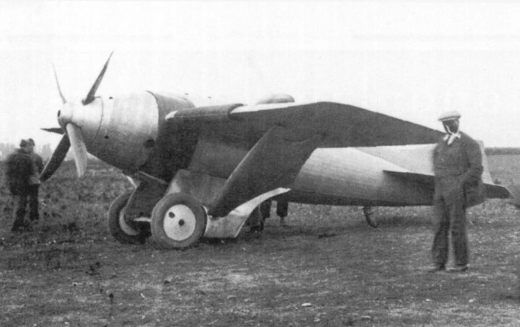
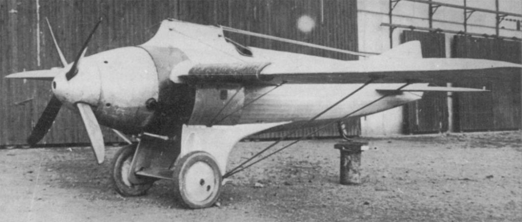
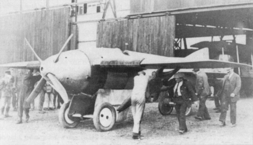
In order to race this new Cup, Salmson upgraded its SB 3 (sometimes referred to unofficially as SB 3bis). In order to increase aerodynamic characteristics, the wing gained increased wingspan (10 m) and surface area (19 m²). The center of gravity of the aircraft was located at 35% of the length of the wing chord. However, the resistance caused by the thick struts of the first configuration led Beshero to install on the SB 3 bis braces above and below the wing. The engine drove a four-blade propeller formed by two two-bladed propellers mounted relative to each other at an angle of 90° with 60 cm in length. This displacement relative to the axis caused vibrations; to fix this, a flat cylindrical screen was placed in the gap between the screw and the engine. The sides of this deformable thin sheet absorbed spontaneous movement of the screws.
In late May 1924, Beshero had not yet found a pilot for the SB 3 bis. Thanks to the assistance of the Assistant Secretary of State for Aeronautics (sous-secrétaire d’Etat à l’Aéronautique), a volunteer was found – Lieutenant Georges Férigoule in Istra. After the test flight, Ferigul found a rather limited lateral control, but acknowledged that the aircraft has some interesting features. The only drawback was the completely insufficient cooling of the “forced” engine, which developed 800 hp on take-off. To solve this problem, Salmson installed a new pump to accelerate the passage of water in the radiators. But during the flight, the thin radiator bands were crushed by an overly powerful pump. The tank with engine cooling water, placed in an L-shaped fairing in front of the pilot, was depressurized and burned Ferigul’s face. Fortunately, his eyes were protected by flying goggles … Forced to land. the pilot refused to continue the competition that was won by Sadi Lecointe on the Nieuport 29.
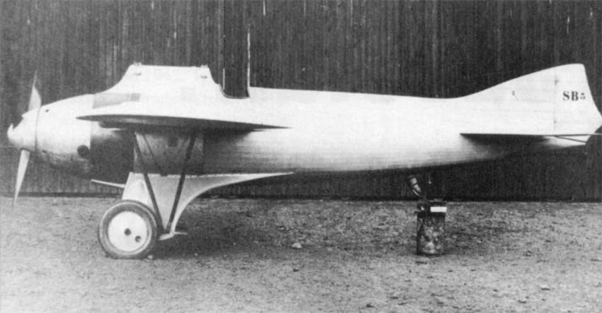
1925 was the last race for the cup with this name. the new rules were almost identical to the rules of 1924, except that victory in the race required speeds of at least 300 km / h and that flights were conducted from 07-00 to 17-00. Only two aircraft fought for their victory: Nieuport-Delage with a 500-horsepower Hispano engine and the Salmson Béchereau SB-3, which again underwent changes. Since the designation SB 3ter (designation not found in the company’s documentation). To participate in races in 1925, Beshero installed a wing with a span of 8 meters and an area of 15 m² on SB 3 bis; The water circulation system on the machine was also revised.
On October 18, two competitors attended the launch: Sadi-Lekuant at Nieuport-Delage and Ferigul at Salmson-Béchereau. Ferigul took off first at 07-30, but after passing ½ turn he had to land. However, at 10-15 he performed a second take-off. However, after two laps, he landed because the engine was very hot. Despite numerous attempts to improve the cooling system, satisfactory results were not obtained. It can be added that the empty weight of SB 3 ter was 1350 kg, and the total weight reached 1580 kg. The maximum speed of SB 3 was estimated at 360 km / h, making it the fastest modification of SB 3.
SB 3 ter ended its days as a flying laboratory for the final tests of the 18 CMb engine, which was a supercharged version of the 18 CMa. It was then suspended from the ceiling of the Salmson workshop in Billancourt, where during the occupation was destroyed by fire during the Allied bombing.
SB-3
1923
Engine: 1 x 520 hp Salmson 18CMb
Wingspan: 8.16 m
Wing area: 17 m²
Length: 8.10 m
Empty weight: 1350 kg
Total weight: 1700 kg
Wing load: 100 kg / m²
Power load: 3.1 kg / hp
Max speed: 350 km / h
Range: 350 km
SB-3 / SB-3a
faired lower struts
SB 3bis / SB-3b
1924 ‘open’ struts, kingpost pylon
Engine: 520 hp Salmson 18CMb
Wingspan: 10 m
Wing area: 19 m²
Length: 8.10 m
Height: 2.50 m
Empty weight: 1400 kg
Normal takeoff weight: 1620 kg
Maximum speed: 320 km / h
Practical range: 350 km
Crew: 1
SB-3 ter / SB-3c
1925
Wingspan: 8.00 m
Wing area: 15 m²
Empty weight: 1350 kg
Total weight: 1580 kg
Max speed est: 360 km / h

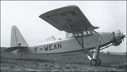
The Salmson Cricri (“Cricket”) was a French light aircraft designed by Paul Deville. Salmson launched work on this new aircraft in 1935, intended primarily for the military for intermediate and advanced training missions.
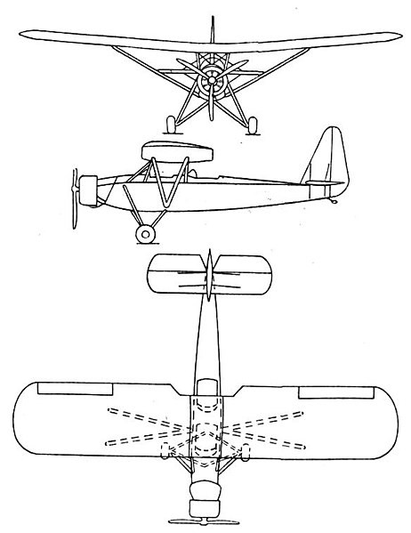
It was a conventional, parasol-wing monoplane with fixed tailskid undercarriage and seating in tandem open cockpits for the pilot and passenger. The negative dihedral wing had the distinction of having a very small forward sweep. A very large tail had been installed. Built mainly in canvas wood but also with metal inserts, it was powered by a Salmson 9Adr engine of 60hp driving a three-blade metal and wood propeller. A relatively high, relatively wide gauge fixed landing gear had been installed on the aircraft. The pilot and his passenger took place in two tandem open cockpits, separated from each other.
Officially designated D.6 by the manufacturer, it received the name of Cricri. Its first flight took place on April 14, 1936. Immediately thirty planes were acquired by the Air Force.
Shortly after receipt of the first of these aircraft, the Navy ordered two fairly similar aircraft for the intermediate training of combat aircraft pilots. These two aircraft received the official designation of D.6-3.
In September 1936, the Air Ministry placed an order for a hundred aircraft under the so-called Popular Aviation program which aimed to promote tourist aviation for the greatest number. These planes were therefore sent to schools and flying clubs across the country.
When World War II broke out in September 1939, production of the Cricri was still underway and several copies were urgently ordered for Air Force schools. But several dozen of them were camouflaged and received tactical codes from combat aircraft. Although generally disarmed, some machines carried in the rear position a mobile Darne 7.5mm machine gun for its own defense. They were widely used for the observation of the battlefield, border surveillance in particular along the Maginot line, or even the direction of ground artillery fire. At least half of the French military D.6s were used for missions other than training.
The majority of Cricri were used during all the French part of the war, and when in 1940 the Franco-German armistice was signed several planes joined the ranks of the German aviation for various secondary missions like the towing of gliders or transport and light postal flights.
345 were built.
Following the war, CFA attempted to revive the design as the Cricri Major. This differed from its predecessor mainly in having a more powerful engine and an enclosed cabin.
Variants:
D6 Cricri
Engine: 1 × Salmson 9 ADr, 45 kW (60 hp)
Wingspan: 9.66 m (31 ft 8 in)
Wing area: 16.0 m2 (172 ft2)
Length: 6.89 m (22 ft 7 in)
Height: 2.18 m (7 ft 2 in)
Empty weight: 287 kg (633 lb)
Gross weight: 575 kg (1,268 lb)
Maximum speed: 150 km/h (94 mph)
Range: 500 km (310 miles)
Service ceiling: 2,450 m (8,040 ft)
Crew: One pilot
Capacity: 1 passenger
329 built
D63 Cricri
dedicated flight trainer version
2 built

Stall: 31 kt / 36 mph / 58 kmh
Cruise: 95 kt / 109 mph / 176 kmh
VNE: 108 kt / 124 mph / 200 kmh
Empty Weight: 270 kg / 595 lbs
MTOW Weight: 530 kg / 1168 lbs
Climb Ratio: 900 ft/min / 5 m/s
Take-off distance (50ft obstacle): 660 ft / 200 m
Landing distance (50ft obstacle): 660 ft / 200 m
In 1933 Georgi Mikhailovich Beriev was appointed head of the TsKB brigade No.5 at the Menzhinsky Factory No.39, which designed naval models. As his second he was appointed Piotr Dmitrievich Samsonov. In December 1933 Samsonov managed to obtain, independently and without Beriev ‘s authorization, the task to develop a new amphibious flying boat.
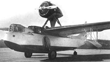
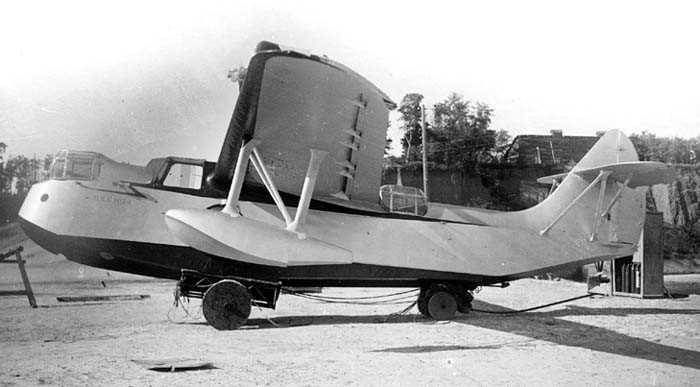
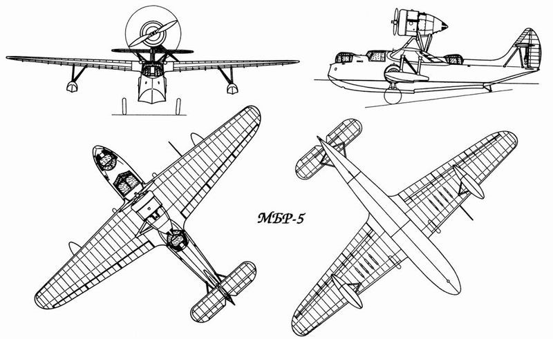
It was a development of the Beriev MBR-2 characterized by its more aerodynamic lines and its retractable landing gear towards the hull, which expanded its possibilities of use. The new model was designed to obtain a better performance model. Although it had a similar scheme, its dimensions and weight were lower and it had a cleaner design, although its construction technology did not differ greatly from the base model, and it could be built in workshops and carpentry shops with personnel with low technical qualifications. The model received the internal designation MS-2 from the TsKB and was known as the MBR-5 (Russian: Самсонов МБР-5), after the acronym for Morskoi Blizhni Razvietchik or Naval Short-Range Reconnaisser.
The MBR-5 was designed as an amphibious high-wing cantilever flying boat intended to serve as reconnaissance and anti-submarine combat aircraft, as well as attack bombers.
The construction was mixed with the wooden hull covered in plywood, which in turn was covered with fabric glued with waterproof lacquer. The structure generally resembled that of the MBR-2 but without the bottom keels. The longitudinal section showed the central keel and two rectangular section stringers. The cross section showed the normal frames and three reinforced master frames located where the wing spars were attached. The support points for the landing gear were also attached to the first two reinforced frames.
The entire covering of the hull was made of 3 mm thick plywood, except on the sides and bottom, where it reached 5 mm.
The wing featured a double spar structure and lacked a centerplane. The spars were of welded JMA steel tubing in a configuration similar to that used on the Ilyushin DB-3B. The wing ribs were lightweight aluminum U-shaped profiles. Welded JMA steel tubes were installed between the two spars to increase structural resistance. The wing had a MOS-27 profile and a trapezoidal shape in the plane with rounded ends. The wing covering was fabric, with the exception of the root zone, where duralumin was used. The ailerons and flaps were constructed of fabric-coated steel.
Fixed implantation stabilization floats were located in the external section of the wing. These floats, aerodynamically shaped, had redients and were made of wood with a veneer coating.
The empennage was designed as an integral part of the fuselage structure with a metallic structure and fabric covering. The horizontal planes, of variable incidence in flight, were braced by means of uprights to the keel structure and were located in the middle position at the height of the empennage, with elliptical-shaped ends. The rudder and elevator, with a metal structure and ribs formed by stamping, had trimmers and a fabric cover. The control of the rudders and surfaces was carried out by cables.
The landing gear featured original design construction. The 900 x 200 mm wheels were retracted into cavities in the sides of the hull and their axles had pneumatic suspension, withdrawing into tubes inserted into the gunwales with the help of a mechanism that pulled a rope. The tail skid, located aft of the second lead, was also retracting in flight. The extension of the gear was carried out by means of a lever in the cockpit. Once the landing gear was extended, the landing gear was fixed by means of a lock with a spring. This setting was signaled by a lamp on the instrument panel.
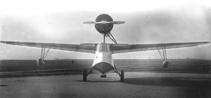
The MBR-5 was projected to use a Wright R-1820-F3 Cyclone engine of 712 hp at 2000 meters, which unlike the MBR-2 moved a propeller in tractor configuration. The 3 meter diameter “Hamilton Standard” propeller ensured a good air flow that guaranteed cooling. The engine was supported by three central supports and two lateral ones towards the left wing, conceived of welded steel tubes. The cowl was a NACA type with a 10-tube annular oil cooler. It was agreed that the production version would be powered by the 775 hp Soviet license-built M-25V version.
The MBR-5 crew consisted of 3: ship commander, navigator with shooter and bombardier functions, and a mechanic. The navigator was located in the forward cabin and the pilot and mechanics side by side in the flight deck. In case of need, the mechanic operated as a gunner for the dorsal station. For this he moved crawling below the midplane to the dorsal turret from which the rear hemisphere could be defended.
In the cabin there was RK-K radio equipment and a POTTE-1V camera for taking panoramic photos. The defensive points were made up of a bow position with a pair of 7.62 mm Degtiariov light machine guns for aircraft and another rear position with similar weapons. The MBR-5 could carry four FAB-50 bombs concealed under a fairing on the wing and attached to D-2 type mounts. The total bomb capacity reached 550 kg.
On the occasion of the start of serial production of the MBR-2 at the Taganrog factory, Beriev was appointed lead builder and given the task of organizing the shipbuilding or TsKB MS there. His team worked tirelessly for two months to ensure the conditions of the transfer to Taganrog. At the end of September Beriev, Samsonov and another group of builders from the No.5 brigade of the No.39 Factory moved towards the new destination.
The work of the new OKB was concentrated on the development of the modification of the MBR-2 with the M-34N engine and the introduction of the model into serial production. Beriev spent virtually all of his time ensuring these important milestones. Under these conditions he had little opportunity to pay attention to the development of the model by his replacement. Despite this, in 11 months the projection and preparation of the work plans of the MBR-5 were completed, which were approved by the main engineer of the VVS RKKA and by November 1934 the construction of the hydrocanoe began in the workshops of Factory No. .39. The transfer to Taganrog prevented the completion of construction in Moscow, so in February the MBR-5 was moved in parts to Factory No.31 in Taganrog.
On September 26, 1935, with the paint still fresh, the MBR-5 prototype left the assembly shop. It received the designation MS-2 for the new TsKB MS at that time and preparation for factory tests began.
The first flight of the prototype was made on October 3, 1935 after some tests on the behavior of the plane in water and lasted 11 minutes. The crew consisted of the test pilot of Factory no.31 A. Ulsien and the technician I. Smaglyuk.
Factory tests continued until December 24, 1935 and comprised a total of 51 flights with a total duration of 9 hours and 8 minutes.
In the results report Ulsien wrote that the runs on land and in the water were stable, but when releasing the pedals there was a marked tendency to pull to the right. The MBR-5 was extremely sensitive to rudder and aileron variations. Before raising the bow there was a certain tendency to slip. During level flight at cruising speed, a lack of stability was observed. The pilot also highlighted visibility problems in landing operations. Despite these difficulties, it was generally considered a pleasant aircraft to fly and easy to control. The MBR-5 demonstrated good manoeuvrability and an excellent rate of climb for flying boats.
A few hours before the end of 1936, the chairman of the evaluation commission and representative of the Directorate of the Red Army Air Forces (UVS RKKA) at Factory No.31, Zagainov, signed the conclusive record of the MBR-5 tests. In this record it was written:
“1 – Despite the construction and production problems, we consider that the MBR-5 with WC (Wright Cyclone) based on the results of the manufacturing tests, due to its type, its general composition, the technical flight data and the behavior in the water can be considered modern and necessary for the naval forces of the RKKA.
2 – The request for 1936 the first group of machines will be received as a field series for the operational study and definition of the neuralgic points.
3 – For the first group to be delivered in 1936 it is necessary to ask the factory to eliminate all the defects pointed out by the military representatives of the UVS RKKA in the Factory No.31 and the MLIS UVS RKKA in the state tests.“
This report filled Samsonov with pride, who was congratulated by Beriev and the collective. It seemed that the model was destined for a long service in the naval aviation of the country. Unfortunately life arranged differently.
On January 3, 1936, the same representative of the UVS RKKA at Factory No.31, Zagainov, presented the head of the 4th department of the UVS, Brigade Commander Bazenkov, with a document entitled “Record of the technical analysis carried out during the state tests of the experimental aircraft of the TsKB MS at Factory No.31: MBR-2M-34N and MBR-5”.
The minutes attached to this document indicated 159 points obtained through external and internal visual analysis, including opinions in relation to the power plants and installed equipment. It was clear that answering all these points would require a fair amount of time.
In practice, the solution to the defects took the entire winter, spring and early summer, to which a fire that partially affected the aircraft contributed. When the second stage of state tests began, the liquidation of the defects had not yet been concluded.
In the second part of the flight tests, the LIS test pilots Noman, Kosheliov, Ershov and Ryabchenko joined. The general opinion of these pilots was that the aircraft was pleasant to fly, light to control and had good manoeuvrability. As a negative aspect, it demanded too much attention during takeoff with the center of gravity advanced. This opinion practically coincided with that obtained during factory tests.
Subsequent flights demonstrated some instability during navigation. To solve this difficulty, at the beginning of 1937, work began with the assistance of personnel from department No.2 of the TsAGI (Flyingboat). It was decided to study the behavior of the flyingboat with test weights of 3,000 and 3,300 kg in the original composition and then displace the netting 40 cm and repeat the tests. These works were carried out between July 25 and until the month of September.
On October 2, 1937, during the transfer flight from Taganrog to Sevastopol for the development of state tests, after a rudder maneuver the plane plunged head-on into the water during takeoff. The strong blow ended up damaging the nose of the flyingboat and it was left with the floats up. Fortunately none of the crew was injured.
It took three days to get the flyingboat out of the bottom. It should be noted that the tapes on which the results of the flight were recorded were so damaged by seawater that it was impossible to use them. Work to restore MBR-5 was suspended.
The MBR-5 was restored for the month of September 1936, but by this time the VMF had lost interest in the model and tests were not continued. By that time, the MBR-2 with the M-34N engine had already entered series, which, both in terms of its capacity and its seaworthiness, surpassed the MBR-5. On the other hand, the TsKB MS was preparing for the first flight of the MDR-5 (TsKB MS-4), working on improvements to the KOR-1 and there was no time to devote to a failed model.
Under these conditions, Samsonov left Beriev ‘s KB and returned to Moscow, concluding the story of the MBR-5.
MBR-5
Powerplant: One 712 hp Wright R-1820-F3 Cyclone
Wingspan: 15.5m
Wing area: 32.5 m²
Length: 11.2m
Height: 4.86m
Empty weight: 2060 kg
Maximum takeoff weight: 3260 kg
Total load capacity: 950 kg
Wing loading: 95.5 kg/m²
Power load: 4.4 kg/hp
Maximum speed at sea level: 256 km/h
Maximum speed at altitude: 306 km/h
Cruising speed: 220 km/h
Landing speed: 110 km/h
Time to 3000 m: 8 min
Practical range: 750 km
Practical ceiling: 7500 m
Armament: 4 x 7.62 mm Degtiariov machine guns
Bombload: 550 kg
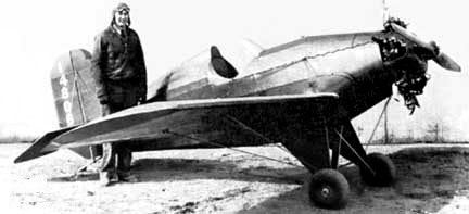
The 1935 single place Wildcat designed by Art Sampson registered N14806, was the example built.
Engine: 65hp Velie M-5
Wing span: 22’3″
Length: 15’1″
Useful load: 315 lb
Max speed: 150 mph
Cruise: 130 mph
Stall: 50 mph
In 1935 Salzman Aircraft Services built the SL-1 two place cabin monoplane registered N X14525. Powered by a 90hp Wright Gipsy, the registration was cancelled on 1 November 1935.
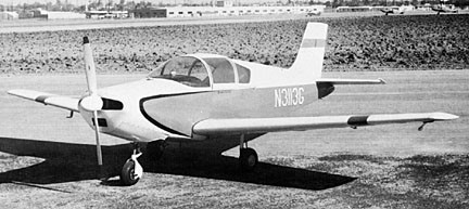
Designed by George Stark as the Salvay-Stark Skyhopper, the prototype TT-1 (N3113G) with a 90hp Continental, was built by Al Trefethen and Art Thistle. It first flew on 9 November 1959.
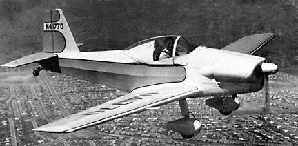
The 1946 Skyhopper 10 plans were marketed for home-builders with a 65hp Continental engine. Designed to sell for around $1,000, a prototype, N41770, was built.
The Skyhopper 10 design modified by Al Trefethen in 1959 as tri-gear Sport Aire II. Also seen under the company names of Avia-Boosters and Skyhopper, but still the same Salvay-Stark design.
It was claimed to be the inspiration for the 1948 Morrisey Nifty.
The Skyhopper 11 of 1959 two place version of the Skyhopper 10 had a greater span wing and 65-85hp Continental; also 108-125hp Lycoming. Registrations N197N, N4787T and possibly others.
Skyhopper 10
Engine: Continental, 50hp
Wingspan: 25’0″
Length: 18’10”
Useful load: 315 lb
Max speed: 130 mph
Cruise speed: 120 mph
Stall: 42 mph
Range: 275 mi
Seats: 1-2
Skyhopper 11
Engines: Continental 65-85hp; Lycoming 108-125hp
Wingspan: 26’4″
Seats: 2
Sport-Aire II / TT-1
1961
Engine: 125hp Lycoming
Wingspan: 26’5″
Length: 21’9″
Useful load: 475 lb
Max speed: 142 mph
Cruise speed: 128 mph
Stall: 62 mph
Range: 400 mi
Ceiling: 13,000 ft
Seats: 2
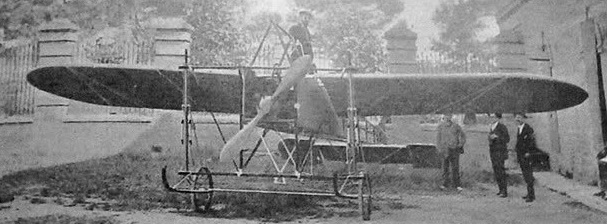
In 1910, mechanic-electrician of the Carcel Modelo de Valencia, Arturo Salvador Gómez, designed and constructed a monoplane at Valencia, Spain, completing the craft in 1911.
The airplane was presented in public on the occasion of the Valencia-Alicante-Valencia aerial raid and subsequent Aviation Festival held at the airfield of La Malvarrosa Beach from 29 to 31 July.
Lacking the engine, the plane was bought by the Aragonese pilot Gregorio Campaña, who had broken his own design plane by falling into the water during the Raid. Campaña intended to equip the Salvador monoplane with the 50 hp Anzani engine from its shattered plane. On August 6, 1911, Campaña departed from Valencia in the direction of Huesca taking with him the plane of Salvador and the remains of his own.
He arrived in Huesca on 9 August and flew on 11 and 12 August. It is not know if the flights made were with the airplane of Salvador with the Anzani engine or if he repaired his own airplane.
Wingspan: 8.9 m
Length: 9 m
The Salmson-Béchereau SB-7 was a fighter aircraft built by French company Salmson in 1925. The SB-7, listed elsewhere as ‘AMBC1’ single-seat, was a high-wing monoplane of all-wood construction, with a canvas coating. Only one aircraft was built, and it was intended as a navalized SB-5.
Only the one was built.
Engine: 1 × Salmson 18Cmb, 390 kW (520 hp)
Propeller: 2-blade
Wingspan: 14.00 m (45 ft 11 in)
Wing area: 39 m2 (420 sq ft)
Length: 11.15 m (36 ft 7 in)
Height: 3.00 m (9 ft 10 in)
Empty weight: 1,600 kg (3,527 lb)
Maximum speed: 200 km/h (120 mph, 110 kn)
Crew: Two
