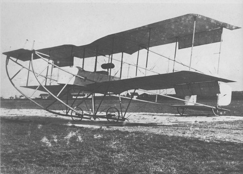
Canadian Aerodrome Company Baddeck 1
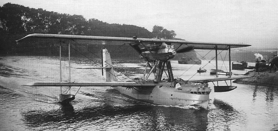
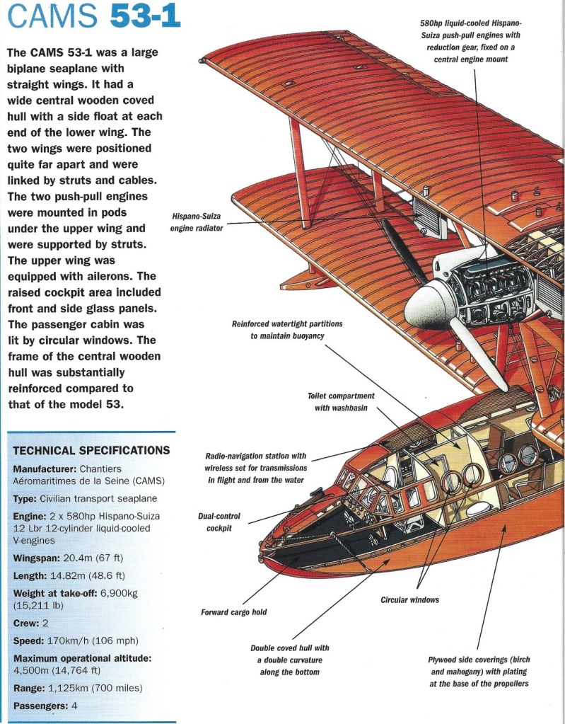
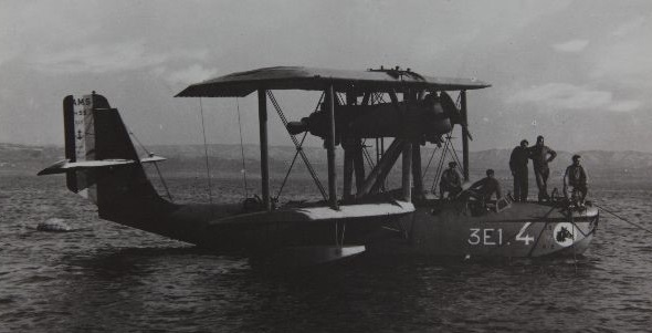
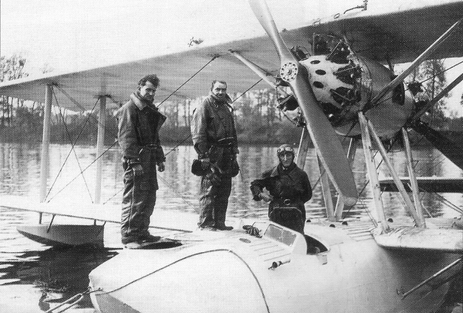
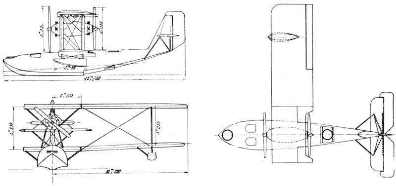
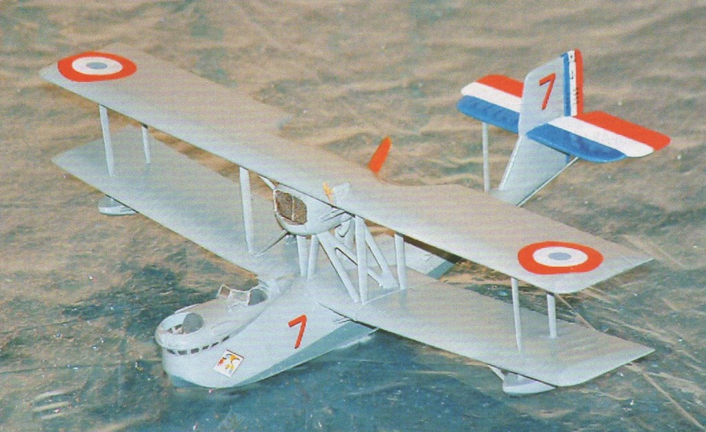
The CAMS 55 design was derived from the unsuccessful CAMS 51 and followed the familiar Chantiers Aéro-Maritimes de la Seine (CAMS) formula of a conventional biplane flying boat configuration with tandem tractor-pusher engines mounted in the interplane gap. The cockpit was open, and there were open gun positions in the bow and amidships. The bow also incorporated an observation balcony with windows sloped to afford a good downward view.
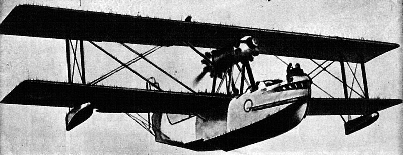
A single prototype was followed by two aircraft to compare different engine installations, one with air-cooled radials and the other a liquid-cooled V engine; in the end, the French Navy ordered some of each. Eventually, 15 escadrilles were equipped with CAMS 55s of various subtypes, replacing the Latham 47 in some units, and in turn being relegated to secondary duties when the Breguet Bizerte became available in 1936. Twenty-nine remained in service at the outbreak of World War II, with the last examples serving with Escadrille 20S in Tahiti until January 1941.
Variants:
55.001 – prototype with Hispano-Suiza 12Lbr engines (one built).
55J – engine test version with Gnome et Rhône licence-built Bristol Jupiter engines (two built).
55H – engine test version with Hispano-Suiza 12Lbr engines (two built).
55/1 – production version with Hispano-Suiza 12Lbr engines (43 built).
55/2 – production version with Gnome et Rhône licence-built Bristol Jupiter engines (29 built).
55/3 – version with all-metal hull for French Navy requirement for long-range flying boat. Prototype destroyed early in test programme (one built).
55/6 – version with all-metal hull and floats, saving 400 kg (882 lb) of structural weight; deemed too expensive to produce (one built).
55/10 – version with geared Gnome et Rhône Jupiter engines and increased fuel tankage (32 built, including four tropicalised machines).
Powerplant: 2 × Gnome et Rhône 9Kbr, 370 kW (500 hp) each
Propeller: 4-bladed fixed pitch
Wingspan: 20.4 m (66 ft 11 in)
Wing area: 113.45 m2 (1,221.2 sq ft)
Length: 15.03 m (49 ft 4 in)
Height: 5.41 m (17 ft 9 in)
Empty weight: 4,590 kg (10,119 lb)
Gross weight: 6,900 kg (15,212 lb)
Maximum speed: 195 km/h (121 mph, 105 kn)
Cruise speed: 150 km/h (93 mph, 81 kn)
Range: 1,280 km (800 mi, 690 nmi)
Service ceiling: 3,400 m (11,200 ft)
Rate of climb: 2.2 m/s (430 ft/min)
Crew: 4
Armament: 4 × trainable 7.5 mm (0.295 in) machine-guns
Bombload: 2 × 75 kg (165 lb) carried under lower wing
55/11 – long-range patrol version (one built).
55/14 – version with all-metal hull (one built).
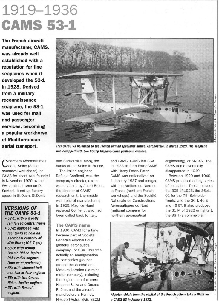
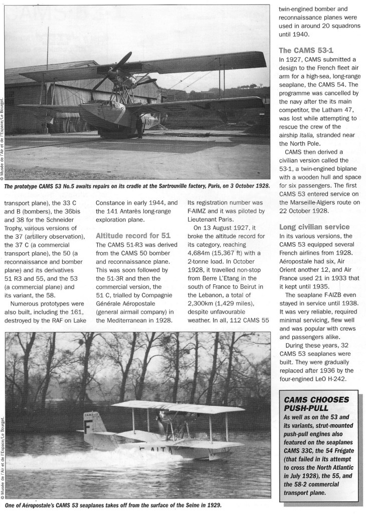
The CAMS 51 was a transport flying boat built in France in the mid-1920s. Designed by Maurice Hurel as a private venture by Chantiers Aéro-Maritimes de la Seine (CAMS), it was a conventional biplane with two radial engines mounted in a tractor-pusher installation in the interplane gap. The first flew in 1926.
One example (the 51C) was sold to Aéropostale, which used it for tests in preparation for transatlantic services.
CAMS also built a militarised version as the 51R3 in the hopes of interesting the French Navy in it as a reconnaissance aircraft, but no order was forthcoming.
A final aircraft was built as a record-breaking machine originally designated 51-3 R that broke the world payload-to-altitude record on 18 August 1927 by lifting 2,000 kg to 4,684 m (15,368 ft). This aircraft was later used as a pathfinder for French airmail routes to South America.
CAMS 51C
Powerplant: 2 × Gnome et Rhône 9Aa, 283 kW (380 hp) each
Wingspan: 20.40 m (66 ft 11 in)
Wing area: 115.0 m2 (1,237 sq ft)
Length: 13.78 m (45 ft 2 in)
Height: 5.00 m (16 ft 5 in)
Empty weight: 3,150 kg (6,945 lb)
Gross weight: 5,150 kg (11,354 lb)
Maximum speed: 200 km/h (125 mph, 109 kn)
Range: 100 km (620 mi, 540 nmi)
Service ceiling: 4,600 m (15,100 ft)
Crew: two
Capacity: four passengers
For shipborne observation/patrol, CAMS’ bay-windowed 37A first flew in 1926. About 150 were produced in the inter-war years. With its Lorraine 450hp broad arrow V12 and coarse pitch and small diameter pusher propeller it lasted longer than most with one example being operated by the Free-French from Tahiti. It could be operated from land strips when a wheeled main gear was attached, but was not capable of amphibious use since it could neither take off nor land on water in this configuration.
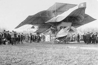
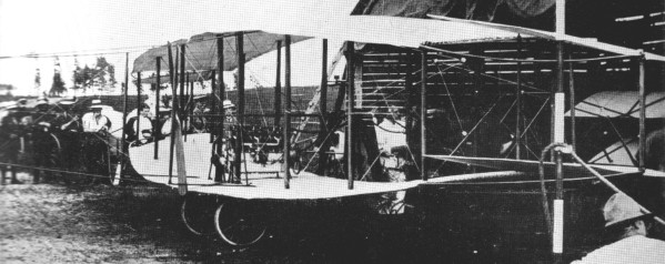
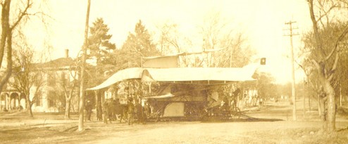
Henry Laurens Call was a writer, a member of the American Association for the Advancement of Science and the designer of this huge, complicated craft, which was powered by two 20hp Curtiss engines, spanned 41 feet and weighed 3,000lbs. It was intended to transport several passengers in the air, on water and on roads, with hot food and all kinds of comfort. However, Call stated that there were too many trees in Girard, Kansas where it was built, and the roads were not very good, so he was never been able to get up a speed of more than 18 miles per hour, rather than the thirty miles an hour he claimed was necessary for the ship to rise in the air.
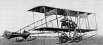
The 1910 BIS No. 2 biplane was designed and built by Bylinkin, Iordan and Sikorsky in Russia.
Span: 26’3″
Length: 26’3″
Weight loaded: 473 lb
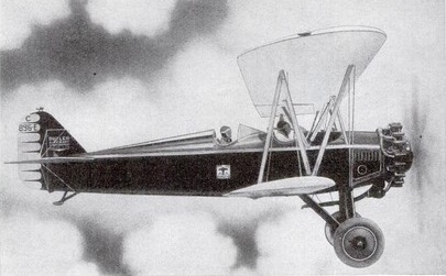
The Butler Blackhawk, designed by Waverly Stearman and engineered by M.C.Baumann, seats three with a Wright Whirlwind engine.
Top speed: 130 mph
Cruise speed: 110 mph
Endurance: 5 hr
Useful load: 1040 lb
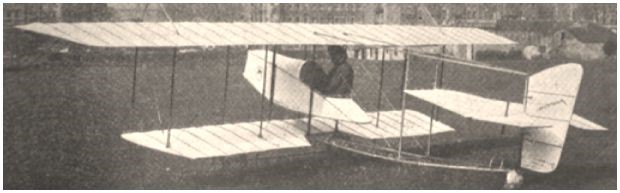
The Motorplane was built at Bath, Somerset, UK, in 1912 by Eldon and Gilbert Bush following the proficiency which they gained with their own gliders and upon professionally-built aircraft. In its original form, as the Bush No. 8, the nacelle was of small cross-section and it was intended to fit an in-line engine. When it proved impossible to obtain an engine of this type at a reasonable price the Bush brothers accepted the loan of a 50 h.p. Gnome rotary, the nacelle being widened accordingly to accommodate it. The machine was then re-designated the Bush No. 9, and it was planned that Eldon Bush should demonstrate it at Hendon. However, while on test at Keynsham the propeller shaft broke and it was not possible to secure a replacement engine before he had to go to Canada on business.
A biplane pusher with a closed nacelle and ailerons at upper and lower wings, built in München, Germany, during 1911-1912. A big rounded tube construction holds the elevator in front. Double rudder at the back.
