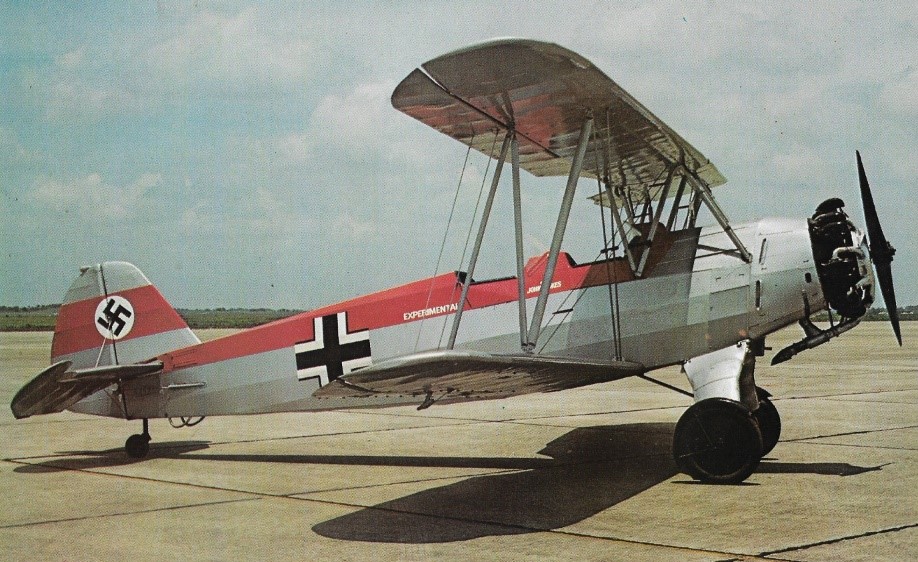
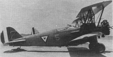
The development of the Fw.44 with the Focke-Wulf Flugzeugbau started in 1931, and the Fw 44A prototype first flew in the summer of 1932 powered by Argus As-8 in line engine which was replaced by the Siemens-Haiske Sh 14a radial engine in the production aircraft. Aerobatic champion Gerd Achgelis conducted the maiden flight of the Fw 44 Stieglitz (goldfinch) trainer late summer 1932.
In its basic form the type had severe handling problems, and these were eradicated by the newly arrived Kurt Tank in an intensive development programme that turned the Stieglitz into a superb aerobatic machine.
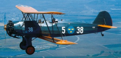
In addition to export orders from Bolivia, Chile, China, Czechoslovakia, Finland, Romania, Switzerland and Turkey, the Fw 44 was built under licence in Argentina, Austria, Brazil, Bulgaria and Sweden (85 designated Sk-12). The major operator was the Luftwaffe with the Fw 44B using the 109-kW (135-hp) Argus As 8 inline, followed by the Fw 44C that reverted to the Sh 144. Variants of the Fw 44C with detail improvements were the Fw 44D, F and Fw 44J. The Sk 12 Swedish license built Focke Wulf Fw 44J was first delivered to the Swedish Air Force Flying School in 1938.
Fw 44A Engine: Sh 144, 112kW (150hp) Span: 9m (29ft 6.25in) Length: 7.3m (23ft 11.5 in) Armament: none Max TO weight: 900 kg (1,984 lb) Max speed: 115 mph at sea level Operational range: 419 miles.
Fw 44B Engine: Argus As 8, 109-kW (135-hp)
Fw 44C Engine: Argus Aces 10C, 240 hp Prop: two-blade fixed pitch 2,80 m diameter Wimgspan: 17,76 m Length: 10,57 m Height: 3,04 m Wing area: 35,00sq.m Empty weight: 1065 kg MTOW: 1580 kg Fuel: 2 x 75 lt Vmax: 191 Kmh Vcruise: 175 km/h ROC: 1000 m in 4 min Ceiling: 5000 m Range: 640 km
Fw 44D Engine: Argus Ace 10D or E, 270 hp Prop: two-blade fixed pitch 2,80 m diameter Wingspan: 17,76 m Length: 10,57 m Height: 3,04 m Wingarea: 35,00 sq.m Empty weight: 1095 kg MTOW: 1475 kg Fuel: 2xX 75 lt
Fw 44E Engine: Argus Ace 10D or E, 270 hp Prop: two-blade fixed pitch 2,80 m diameter Wingspan: 17,76 m Length: 10,57 m Height: 3,04 m Wingarea: 35,00 sq.m Empty weight: 1095 kg MTOW: 1475 kg Fuel: 2xX 75 lt
Engine; 1 x 140hp Siemens Sh 14A Wingspan; 9.00 m / 30 ft 6 in Length; 7.30 m / 24 ft 11 in Height; 2.72 m / 9 ft 11 in Wing area; 20.00 sq.m / 215.28 sq ft Max take-off weight; 860 kg / 1896 lb Empty weight; 500 kg / 1102 lb Max. speed; 188 km/h / 117 mph Cruise speed; 160 km/h / 99 mph Ceiling; 4200 m / 13800 ft Range; 720 km / 447 miles Crew; 2
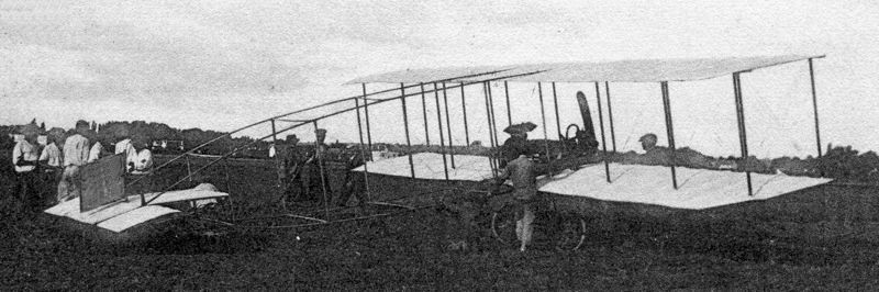
Brothers Tadeusz and Władysław Florjańscy (“Florjański” being a singular form of the name) built in Lwów (then Lemberg in Austria-Hungary, now Lvov in Ukraine) a biplane aircraft in 1914. When the war broke out the plane was nearing completion and was confiscated by military authorities and earmarked for evacuation. However, rapid advance of Russian army led to its capture and being finished by new owners which apparently made some operational reconnaissance flights before it crashed.
This big tractor biplane was known under two different names, after Jean Florencie and Georges Copin. It was powered by a three-cylinder Anzani and flew at Port-Aviation, France, in late 1909.
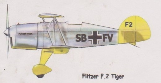
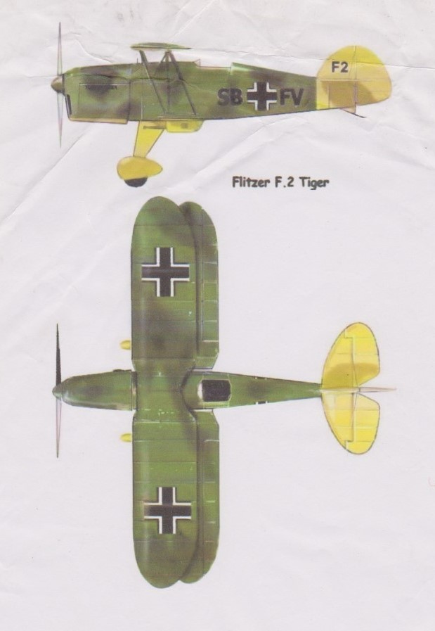
The Flitzer F.2 Tiger is a wooden airframe, conventionally braced, with elliptical wings, elliptical tailplane, and an ‘Avia’ style fin and rudder. The F.2 is intended to be powered by a Walter LOM inline of 140-170 hp.
For taller pilots, the seat can be lowered by at least 3 inches by means of a stirrup block method.
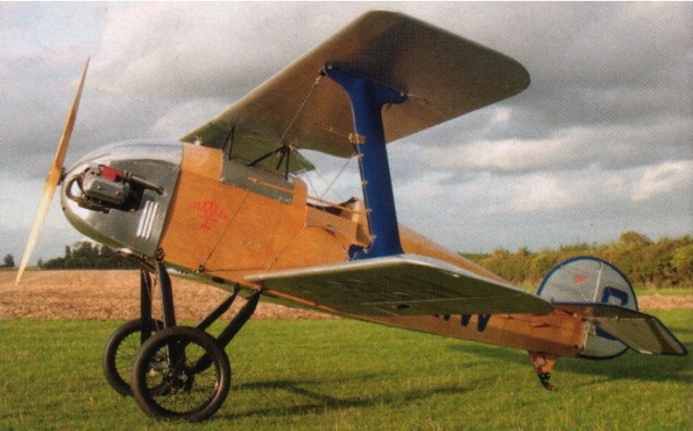
Designed by British aviation artist Lynn Williams, the Flitzer is a mythical inter-war sport plane. The original Z-1 prototype was powered by an 1835cc VW. Since first flight, the LSA 1834cc VW-powered prototype Flitzer Z-1 has flown over 70 hrs, without any changes to rigging or trim of the machine, other than for experimental purposes.
The aeroplane has been dived to over 125 mph, controls firming-up appropriately, without any aerodynamic buzz, and terminal velocity appears to be well short of the flutter regime. It flies hands-off in the cruise (Vc = 86 mph.) and will complete a 360 deg. turn in 7 secs at this speed. At Vc, deliberate displacements in pitch, both positive & negative, result in stick-free re-acquisition of flightpath in 1/2 oscillation, ie. deadbeat damped in cruising flight.
This was followed by the stronger Z-21, incorporating a longer span horizontal stabiliser and other refinements, still with a 22in wide fuselage.
The Z-21A features a wider fuselage, at 24in at the cockpit.
Z-21A
Flitzer plans comprise 33 mostly A1 size sheets, and are comprehensively illustrated, with much text, and many perspective, exploded views of components.
All metal fittings are drawn full size, and plans have been updated to reduce time and cost of fabrication. With the American Ellison EFS-2 slide carburettor, developed power is in the order of 60+ hp., and the aeroplane gets airborne in 7 seconds in about 130 yds. At approx. 80% MAUW., rate of climb averages 700 fpm., and maximum speed straight-&-level is just over 90 mph. with the currently un-refined ‘cruise’ propeller, at 3000 rpm., red line being 3300 rpm for this engine, so more performance may be achieved via propeller improvement.
Z-21A
Stalls are innocuous, with or without power: 44 mph. Straight ahead power off, and below 30 mph. IAS at full power – with gentle wing drop and plenty of pre-stall warning in terms of hunting in pitch and short-period wing rock. Control about the yaw and roll axes is maintained below stall. Recovery is immediate on relaxation of stick pressure. The true stall would not develop with the Z-1 prototype’s “small tail”, the aircraft mushing in stable sink at an indicated 44 mph., power off (a safe condition). But with the 6% area increase in the horizontal tail, as shown on the Z-21 “plans” version, a clean g-break is now achievable, and with full power the ‘straight’ , unaccelerated stall occurs at an angle of +35 degrees of pitch.
Best angle of climb is achieved at 45 mph. IAS, and best ROC at 60 mph. Approaches are flown at 60 mph., reducing to 55-50 over the hedge, touching down at about 45. The latter figures may be reduced with the slightly larger tailplane shown on the plans. The machine copes well with crosswinds on a narrow farm strip, despite not being equipped with brakes or a steerable tailwheel, although these options will be included on a later sheet. Streamlined main undercarriage leg fairings have been fitted, and add both to the machine’s appearance, and also to performance.
Z-21A
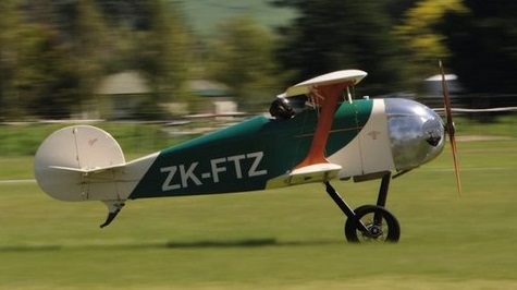
Some fifty sets of Flitzer drawings are in circulation world-wide, with several examples being built in the USA, as well as in Australia, NZ, Italy, France, Germany, Canada, S.Ireland, and the UK. The second Flitzer, the ex-Bell-Aeromarine proof-of-plans Z-21A demonstrator flew in ’99, and handled beautifully, approaches with the larger tail confirming the predicted reduction of some 5 mph in IAS by comparison with the prototype Z-1, the latter a/c having reviously been tested with a facsimile Z-21 tail. The Z-21A s specifically identified by its 2″ wider fuselage (24″ cockpit width compared with 22″ on the prototype and basic Z-21)
Maximum weight authorised is 750 lbs., and structural improvements, higher tailplane reserve factors, and the use of 4130 steel on the plans versions, have contributed to an increased overall reserve factor at this weight. Empty weight is 479 lbs., and fuel tank capacity is 8.5 gals. (Imperial). The aeroplane is comfortable to fly, and the cockpit is surprisingly warm and free from draughts, despite the small ‘period’ aeroscreen. The growl from the paired exhaust pipes is a sound quite unlike the typical VW ‘flutter’ , more like a ‘twenties long-stroke V-type. The machine never fails to attract attention wherever it is seen, and has been flown by several eminent test pilots.
Plans are extremely detailed and graphic containing all information needed, down to options on engine installations, exhausts and induction pipe offsets to provide the aerodynamically cleanest and most attractive engine cowling, as well as they’re being a build manual. Section profile is USA35B, with excellent L/D and gentle stalling characteristics.
Flitzer control surfaces have no mass or aerodynamic balancing, but are well harmonised.
The slightly more compact Stummel Flitzer has a shorter fuselage with raked cabane, a larger tank bay and rounded flying surfaces. This comes in two versions, the Stummel Flitzer S and the Stummel Flitzer R, optimised for aerobatics using engines in the 60-100hp range. The fuselage is strengthened to +6/-3G and balanced, slaved ailerons have been added to the upper wing.
By 2008, more than 200 sets of plans had been sold, in 33 illustrated 3x2ft sheets. All metal fittings drawn to full size. The sub versions are all derivatives, and come as modifications to the basic plans. One modification is the use of the round Stummelflitzer vertical stabiliser on the Z-21 / Z-21A. Flitzers use conventional construction with plank spars and built-up ribs forming the USA 35B wing section, squared off with laminated wood wingtip bows. All ribs are identical.
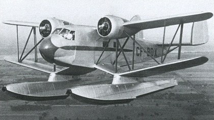
The Fleet 50 Freighter was a twin-engine biplane Canadian general utility aircraft designed and built by Fleet Aircraft. Design was started in 1936 to create a general purpose twin-engined utility aircraft for the Canadian market. It was designed as a short take-off freighter with features added to ease cargo handling. The Freighter was a biplane with the lower wing an inverted gull wing with either a float or wheel landing gear. Two radial piston engines were mounted in nacelles on the upper wing panels.
The fuselage structure was welded steel tubing with duralumin formers, and a semi-monocoque duralumin nose section. The wings were stressed-skin metal structure on the inboard panels and fabric-covered wood beams and duralumin ribs on the outboard panels. The fuselage had room for two crew and up to ten passengers. Large doors and a roof-mounted chain hoist were fitted for use in the cargo role.
The prototype designated the 50J first flew on 22 February 1938, powered by two 285 hp (213 kW) Jacobs L-5MB 7-cylinder radial engines. It was later re-engined with 330 hp Jacobs L-6MB engines and re-designated the 50K. A further four aircraft were built, all with L-6MB engines.
None of the aircraft was operated for long, as the design was under-powered and could not maintain altitude on only one engine.
Fleet 50K landplane Engines: 2 × Jacobs L-6MB 7-cylinder radial engine, 330 hp (246 kW) each Length: 36 ft 0 in (10.97 m) Wingspan: 45 ft 0 in (13.72 m) Height: 13 ft 1 in (3.99 m) Wing area: 528 ft² (49.05 m²) Empty weight: 4600 lb (2087 kg) Gross weight: 8326 lb (3777 kg) Maximum speed: 150 mph (241 km/h) Range: 650 miles (1046 km) Service ceiling: 15,000 ft (4570 m) Crew: 2 Capacity: 10 passengers or freight
Fleet Aircraft Company built eleven Consolidated Model 21 aeroplanes for its parent company, Consolidated, in 1936 and 1937. Ten of these were exported to Mexico as basic trainers for the Mexican Air Force. The eleventh was produced in 1937 as a demonstrator for Fleet, which tried to interest the RCAF in this large biplane. Unfortunately, the days of the biplane were already numbered, and monoplanes were emerging from the world’s aircraft factories in greater quantities. Originally built as the Model 21M with a Pratt & Whitney R-985 Wasp Jr. engine, some were converted to a Model K with the Jacobs L-6MB engine.