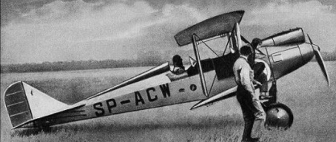
The PZL-5, designed by Malinowski and Kozlovski, was the first sporting aircraft in Poland that was built in series. The first prototype flew in 1928.
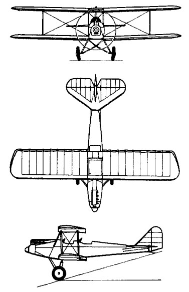
The PZL-5, designed by Malinowski and Kozlovski, was the first sporting aircraft in Poland that was built in series. The first prototype flew in 1928.
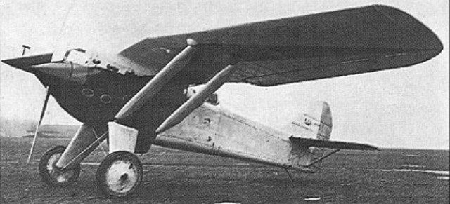
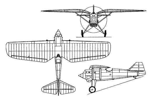
The first fighter of indigenous Polish design, the P.1 produced by the Paristwowe Zaklady Lotnicze (P.Z.L.), or National Aviation Establishment, embodied several technical innovations. Designed by Zygmunt Pulawski, the P.1 was of all-metal construction, its most novel feature being the “gulling” into the fuselage of the centre section of the high wing, thus eliminating the normal cabane. This both reduced drag and improved the forward view for the pilot. Powered by a 12-cylinder water-cooled Hispano-Suiza 12 Lb Vee-type engine affording 630hp for take-off, the first prototype, the P.1/I, was flown on 25 September 1929. Armament comprised two 7.7mm Vickers machine guns. The second prototype, the P.1/II, featured a repositioned radiator bath and redesigned vertical tail surfaces, and joined the test programme in March 1930. Further development was discontinued in favour of radial-engined variants, as the Polish air arm, the Lotnictwo Wojskowe, was biased against liquid-cooled engines.
Engine: Hispano-Suiza 12 Lb, 630hp
Max take-off weight: 1580 kg / 3483 lb
Empty weight: 1118 kg / 2465 lb
Wingspan: 10.85 m / 36 ft 7 in
Length: 6.98 m / 23 ft 11 in
Height: 2.96 m / 10 ft 9 in
Wing area: 19.50 sq.m / 209.90 sq ft
Max. speed: 302 km/h / 188 mph
Range: 600 km / 373 miles
Armament: two 7.7mm Vickers machine guns
Founded January 1928 as Poland’s National Aircraft Establishment, built the P.1 single-seat fighter monoplane with Hispano-Suiza engine in 1929-1930, and subsequently the P.11 single-seat fighter and P.19 cabin monoplane. The PZL Los medium bomber of 1937 was followed by the Wilk twin-engined fighter, Sum light bomber and Mewa reconnaissance monoplane by the beginning of Second World War. Factories at Warsaw- Okecie (original) and Mielec, latter used by occupying Germans as forced-labour Heinkel factory 1940-44.
Under political reorganization in 1956, the Polish aircraft industry was revived with production of Soviet aircraft and some indigenous types. In foreign markets most Polish aircraft subsequently appeared under the PZL title, such as the PZL-101 Gawron and PZL-104 Wilga utility aircraft of 1960 and 1962 respectively, the first being a development of the Yak-12. The Gawron was used extensively as an agricultural aircraft, along with the PZL-built An-2 biplane, but later purpose-built dusters and sprayers were built. PZL types are produced under three separate organizations: PZL “Warszawa-Okecie” SA, WSK “PZL-Mielec” SA, and PZL-Swidnik SA.
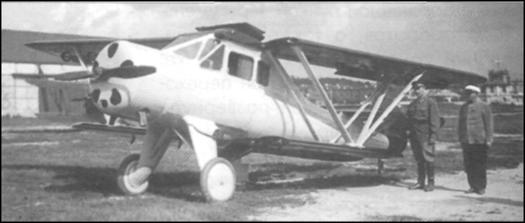
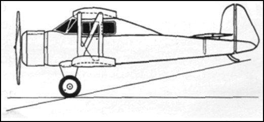
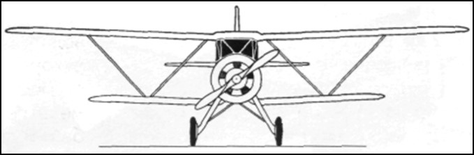
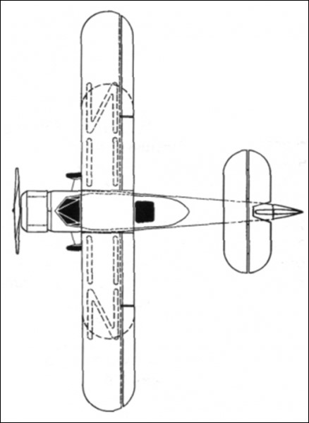
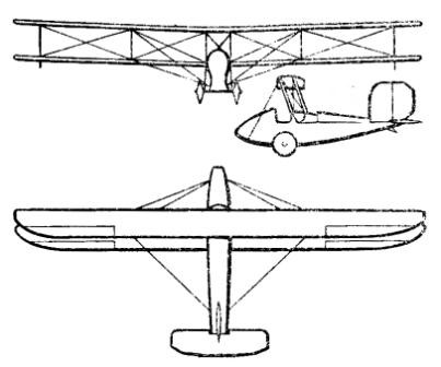
In addition to scientific-investigative work, VS Pyshnov once again decided to try its hand at construction activity. In 1935 he developed the project of a light aircraft that received the name VVA-1 (Military Aeronautical Academy – 1).
The VVA-1 was designed to meet the requirements of a light aircraft contest promoted by Osoaviajim in 1934. During the design, Pyshnov placed special emphasis on obtaining comfort for the passengers, the exterior finish of the model and the decrease in landing speed, obtaining a multi-purpose aircraft intended for use as a trainer, tourism aircraft, light transport and liaison aircraft.
Structurally, the VVA-1 was designed as a sersquiplane with wings of equal width and a closed cabin made almost entirely of wood, using pine for the structure and plywood for the fuselage covering. The cowl was covered with steel plates and the wing and control surfaces were covered with fabric.
The fuselage featured a monocoque structure with a circular cross section. The construction had 17 frames and 4 stringers of variable section (30 x0 30 mm in the engine area and 20 x 20 mm in the tail area, as well as 10 stringers of 10 x 15 mm. The fuselage had a plywood covering of 3 mm in the front and tail area and 2 mm in the central area. To ensure greater rigidity, the fuselage had practically no perforations.
The wing box had a wooden structure with rigid “W” braces. The wing was rectangular in shape with rounded wingtips and consisted of two box-frame spars with three layers of pine and 3mm plywood walls. The leading edge was produced independently, being mounted on the wing once the fabric covering was finished. The wing struts were also made of pine with an aerodynamic profile and their junction with the wing was faired to reduce drag. Ailerons were included only on the upper wing, which also featured flaps that could be operated up to 30º angles. Norton-Shrenk type flaps capable of tilting at 45º were included in the lower wing.
The wing profile of the midline responded to that of the TsAGI-RP profile with decreased curvature, but the thickness responded to the NACA profile with a relative thickness of 10.5%.
The upper wing consoles were fixed to the centerplane located above the closed cockpit. The lower wing was fixed directly to the fuselage and to reduce interference in the joint area it presented an inverted gull configuration. Another notable feature was the possibility of collecting the wings backwards, pivoting on the rear spar. In this way the width of the aircraft decreased from 11 to 3.4 meters.
The tail section featured an unconventional design. The horizontal stabilizer was located quite forward on the tail cone and on top of the fuselage. The empennage was cantilever and was fixed to the last frames of the fuselage. This configuration was specially selected in order to improve the work of the tail unit in the event of a spin entry, by eliminating the influence of one surface on the other.
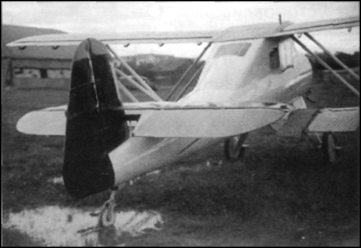
The stabilizer had a main spar located over 27% of the wing chord and a secondary spar located on the elevator attachment edge. The uprights that were attached to the structure on both sides of the fuselage were attached to the main spar. The front of the stabilizer was lined with plywood. The rest was received with tissue. The angle of incidence of the stabilizer could be adjusted on the ground. The structure of the depth rudder was made of wood with a textile covering.
The VVA-1 featured duplicate sticks, but the second stick could be removed. The double control pedals were linked to each other by means of a tube. Elevator control was mixed. In the lower part of the cabin it was rigid, but further on it was still on cables. Control of the ailerons was rigid, while that of the elevator was cable. The aileron actuators could be easily disengaged to allow retraction of the wings.
The main landers featured aerodynamically faired legs and rubber shock absorbers with 700 x 100 mm unbraked wheels. The tail unit also featured spring damping and was free to rotate. The rear landing gear was calculated to install a skid or a wheel, interchangeably.
The powerplant selected was the 110-hp air-cooled M-11 radial engine. The engine was fixed to the fuselage by four points with the help of a frame made of “M” steel. The engine was covered by two hoods, one inside and one outside. To ensure engine cooling, the outer hood had adjustable holes located in front of the cylinders. The flight could be carried out only with the inner hood. For the VVA-1 a special fixed-pitch wooden propeller was designed.
The engine’s power system consisted of two fuel tanks. The main tank had a capacity of 100 liters and was located in the center of the plane. About the cabin. The second tank was located in the fuselage, between the engine and the cockpit instrument panel. The motor feeding could be done from each tank independently or from both. In the upper tank, a floating system was located that indicated the remaining fuel. The lubrication system was taken from the Polikarpov Po-2.
The cabin of the VVA-1 was closed and in the normal version it accommodated three people. The plioto was located in the front left position and behind it was a divan for two passengers. On the pilot’s right side a fourth seat could be installed to use the aircraft’s dual control system. To access the cabin, two doors located on the sides, on the lower wing, were used.
The instrument panel included a speedometer, turn signal and artificial horizon, barometer, clock, compass, rev counter, engine temperature and oil pressure indicator. Lighting was installed for the panel and for the cockpit.
The VVA-1 was built in the workshops of the Military Aeronautical Academy. In the summer of 1935 the plane was ready for testing. In relation to the calculations of the project, the plane turned out to be much heavier. Calculated for an empty weight of 580 – 600 kg the prototype weighed 845 kg, with a takeoff weight of 1146 kg.
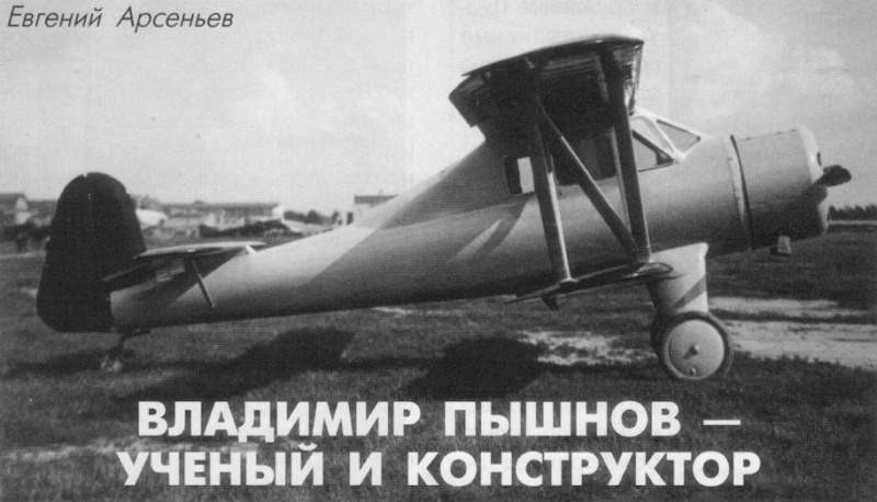
In August 1935 the aircraft was handed over to the NII VVS for development of state tests. NS Kulikov was designated as the main engineer and the test pilot was KA Kaliliets. The test program established 14 flights to establish the benefits and the main operating data. The tests took place between August and September and were carried out without the outer bonnet and without the planned propeller. When testing this propeller, both on the ground and in flight, a large vibration appeared throughout the airframe. For this reason this propeller was replaced by that of a Po-2. With this propeller the vibration did not completely disappear, but it decreased considerably. In the tests, a speed of 156 km/h at sea level was obtained with a takeoff weight of 1146 kg and 145 km/h at 2000 meters of altitude. The height of 1000 meters hated to be reached in 9.83 min and the 2000 m in 26.19 minutes. The ceiling of 2920 meters could be reached in 76.9 minutes. Landing speed with flaps extended was 75 – 90 km/h.
The plane behaved well on takeoff, but it was heavy and the tail lifted with difficulty. It lacked a tendency to take off from the ground, so the pilot felt the need to “force” it. Using the flaps did not improve takeoff, shortening it only by about 60 meters. Another problem was the tendency of the plane to drift during the takeoff run, which forced the pilot to not neglect control of the controls to correct the problem.
The rate of climb was considered very low. To rise to 30 meters, the plane needed to travel 500 or 600 meters, which, together with a run of about 240-300 meters for takeoff, made it impossible to use it at aerodromes with short runways or with obstructions near the end of the runway.
Visibility from the cabin forward and to the left was considered good, to the right and to the sides, bad and to the rear was not possible. Long flights were exhausting for the crew, especially due to the poor distribution of the steering components and the uncomfortable position of the seats.
In calm skies the plane behaved quite well, but in turbulence its behavior was capricious. Maintaining the instrument course was quite difficult as the compass was far away on the panel and it was difficult for the pilot to follow it.
Unlike takeoff, landing was very easy. The aircraft landed with good stability. Without the flaps the landing run increased to about 180 meters.
In the report it was stated that due to the discomfort of the seat, the poor distribution of the instruments and equipment, the excessive sensitivity of the rudder, the low ascent speed and the lousy design of the control organs, the VVA-1 demanded too much attention of the pilot. As positive values of highlighted the excellent stability and ease of handling.
The military pilots pointed out that the performance obtained was too low and the aircraft too heavy, which led to a considerable decrease in the calculated payload capacity. The takeoff and landing runs were too long and the takeoff technique too complex, which confined it to operation on large aerodromes with good runways. The use of the flaps was very ineffective and the landing speed remained high. The poor work of the flap control organs, the uncomfortable position of the control stick, the poor vision through the cockpit glass in bad weather and the absence of rearward and upward visibility were also noted.
In the conclusions of the report it was written: ” due to its performance and operating data, the VVA-1 aircraft is of no interest… “
It was considered useless to make modifications to the plane because it was considered that the main drawbacks of the plane came from its aerodynamic design, but the possibility of building a new example that took advantage of the positive elements of the design was left open, while at the same time managing to eliminate the indicated deficiencies and cover the requested technical specifications. Budget cuts at the Military Aeronautical Academy prevented the construction of this new model.
Given the impossibility of building a new prototype, the first VVA-1 was modified in order to reduce some of the signals made during the tests. Among the changes made, work was done to improve the control of the rudder by reducing its surface and installing a compensation system to reduce sensitivity. The landing gear was modified, a more powerful powerplant was installed and the hood was modified. Added a new fuel tank. The fairings at the junctions between the W-pillars and the wing were removed. These changes increased the empty weight of the plane to 1,160 kg, so military use was ruled out, defining the use of the model as a sports and tourism plane.
In 1937 the modernized VVA-1 was delivered to the NII VVS and several familiarization flights were carried out on it. These flights demonstrated stability problems in the vertical axis. The builder was asked to increase the surface of the empennage and replace the wheel train with one made of skis. Lack of funds for development programs at the Military Aeronautical Academy prevented further modifications.
VVA-1
Powerplant: One 110 hp M-11
Wingspan: 11.0 m
Wing area: 21.28 m²
Length: 7.8m
Height: 2.85m
Empty weight: 845 kg
Maximum takeoff weight: 1146 kg
Fuel capacity: 110 kg
Payload: 301 kg or 2 passengers
Maximum speed: 156 km/h
Minimum flight speed: 100 km/h
Landing speed: 75-90 km/h
Cruising speed: 135 km/h
ROC: 2.05 m/s
Ceiling: 2920 m
Take-off run with flaps: 220-260 m
Landing roll: 180-200 m
Accommodation: 1 – 2
In 1923 the Academy of the Air Fleet and the Military Academy of the RKKA leadership allowed students to build gliders and light aircraft using the academy workshops.
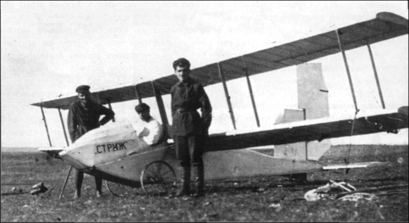
Between 1 and 18 of November of 1923 took place in Uzun-Sirt mountains in Crimea First National Competitions Gliding. In these competitions 10 gliders were presented. Among them were three Air Fleet Academy student gliders named AVF-1 Arap , AVF-2 Strizh and AVF-3 Mastyazhart and built by students MK Tijonrarov, VS Pyshnov and SV Ilyushin respectively. The technical commission, chaired by Professor VP Vetchinkin, after reviewing them, allowed the flight of 9 of them.
Pyshnovs’ AVF-2 Striz (Russian: Пышнов АВФ-2 «Стриж») glider had a biplane structure with long wings. The fuselage was constructed entirely of wood, with cable ties and featured a rectangular cross-section with a curved top. The fuselage structure ended in a horizontal rib towards the tail. The covering was fabric.
The wing trunk was located above the fuselage. The upper flange had an offset of 0.3 meters and the distance between both planes was 0.9 meters, being joined by means of parallel uprights and braced by cables. The wing construction was also made of wood, with textile covering and corresponded to the Prandtl-387 profile. Roll control was carried out by ailerons located in both planes.
The monoplane tail unit featured a large elevator attached to the rear frame of the fuselage and a large area empennage to which the rudder attached.
The landing gear was of the conventional type with two large spoke bicycle wheels whose axle ran from side to side through the fuselage and was attached to rubber shock absorbers. In the tail it had a fixed skate to the structure.
The pilot was located in a cockpit in front of the wing leading edge.
The Pyshnov glider was the second model designed and produced at the Air Fleet Academy (AVF), for which it received the official designation AVF-2 and the nickname “Strizh.” The Strizh was built in the AVF workshops and assembled at the “Aviarabotnik” factory. Unfortunately by the time the competitions started in November 1923 the AVF-2 had not been finished and was sent to the competitions in that state. All the metallic fixings were already installed in the camp of the participants in the competition.
This situation played a negative role in the fate of the glider. The Strizh was not only incomplete, it had not been tested, so construction defects had not been corrected. During the first tests on November 15 the Strizh on several occasions rotated on its axis before reaching takeoff. To correct this difficulty the builders increased the rudder area considerably but after this the glider refused to rise.
As a consolation, in this competition they also failed to launch their gliders SN Lyushin with their “Maori” and VI Cheranovski with their BICh-1 “Parabola”. Despite the difficulties the 17 of February of 1924, during the conclusions of the first competitions of gliding, the builder VS Pyshnov to the present like other builders, received a special award for its creation.
AVF-2 “Strizh”
Wingspan: 10.2 m
Wing area: 12.5 m²
Length: 4.7 m
Height: 1.8 m
Elevator area: 1.6 m²
Keel rudder area: 0.6 m²
Rudder surface area: 0.5 m²
Ailerons surface: 2.2 m²
Empty weight: 60 kg
Wing loading: 10 kg / m²
In 1921, with the help of some fellow students, Vladimir Sergueyevich Pyshnov built his first glider. In November of this year on this glider a group of young students, including Pyshnov himself, BI Cheranovski, VN Belyayev, VV Utkin-Yegorov and others, made more than 20 flights. In the last one carried out, the glider was destroyed and was never restored.
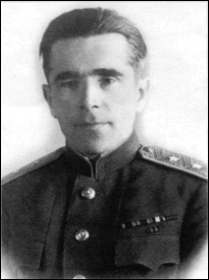
Vladimir Sergueyevich Pyshnov (Russian: Владимир Сергеевич Пышнов) was born on March 6, 1901 in Moscow. In 1918 he finished secondary school at the 3rd Muscovite Gymnasium and in 1919 he entered the Moscow Technical Aviation School, directed by the famous Professor N. Ye. Zhukovski.
In June 1920 VS Pyshnov voluntarily joined the ranks of the Red Army at a call from the school’s leadership and a month later, July 29, 1920 the Revvoyensoviet (Revolutionary Military Soviet) issued an order establishing the transfer of subordination of the school to the Main Directorate of the Red Air Fleet, although methodologically it was still linked to the technical-professional education structure.
Changes continued and the 26 of September of 1920 the Revvoyensoviet N.1946 issued a new order, which established reorganize the School of Aviation Moscow at the Institute of Engineers of Red Zhukovsky Air Fleet (Russian: Институт инженеров Красного Воздушного Флота имени Н. Е. Жуковского) in honor of its creator and on November 23 the state position on the institute was made official.
During the study period, Pyshnov carried out the practices under the guidance of the aeronautical constructor AA Porojovschikov, together with another group of students who worked in his factory as turners, milling cutters and assemblers. On the other hand, from the first year of study Pyshnov decided to try forces in the development of gliders.
In 1921, with the help of some fellow students, he built his first glider. In November of this year on this glider a group of young students, including Pyshnov himself, BI Cheranovski, VN Belyayev, VV Utkin-Yegorov and others, made more than 20 flights. In the last one carried out, the glider was destroyed and was never restored.
These were years of intense development of gliders in the USSR. At the request of the Directorate of the Air Fleet Directorate (Glavvozduxflot), a circle of gliding was created under the auspices of the Air Fleet Scientific Office.
Professor VP Vetchinkin at a meeting on October as November as 1921 asked to name this circle “Paryaschi Poliot” (thermal flying). The first president of the circle was AA Zhavrov, being soon replaced by KK Artseulov. Among the members of this circle, VS Pyshnov was registered.
In May 1923 and from an initiative of the direction of the Academy of the Air Fleet and the Military Academy of the RKKA a military scientific society was organized that greatly promoted the activities of the aviation and planning sections. The AVF leadership allowed students to build gliders and light aircraft using the academy workshops.
By November 1923, the gliding section, with 11 people, participated in the First National Sailing Competitions held in Crimea. Three students from the academy: MK Tijonrarov, VS Pyshnov and SV Ilyushin presented their own gliders named respectively AVF-1 Arap, AVF-2 Strizh and AVF-3 Mastyazhart.
At the Second National Sailing Competitions held in Crimea in September 1924, four-year students Pyhsnov and Tijonrarov were selected for members of the technical committee, led by Professor VP Vetchinkin.
The 2 of April of 1925 there was the first graduation of engineers in the AVF. Among the graduates was Pyshnov, after defending his diploma project under the mentorship of the famous aeronautical builder DP Grigorovch.
After finishing the Pyshnov academy he went on to serve as an engineer in the 8th Squadron of the independent brigade “Krasnaya Moskvá ”. In May 1926, he was placed on the reserve and sent to serve in the industry.
Pyshnov expressed his interest in continuing his studies and in October 1926 he again entered the Military Aeronautical Academy (VVA), where a year later he defended his dissertation, receiving the teaching category. From 1927 he began his work as a teacher at the VVA. As of January 1932, he was appointed head of the chair of Aerodynamics Aeronautics and later, on April 16, 1935, head of the chair of Flight Dynamics.
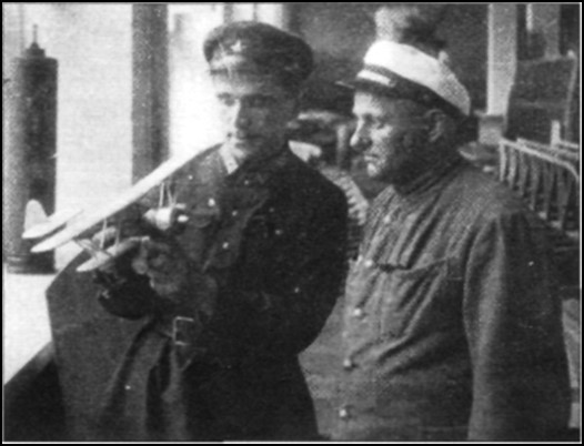
In 1935 Pyshnov developed a light aircraft that received the name VVA-1 of which a copy was built that was flown successfully, although with poor performance.
The 23 of February of 1937 he received the rank of professor and from the 14 of March of 1938, by Resolution No.235 of the SNK, it became part of the Aviation Committee within the Defense Committee of the USSR.
At the beginning of the Great Patriotic War and by order №02201 of the Popular Defense Committee, Pyshnov was appointed consultant to the head of the NII VVS on aviation matters. In this position he stood out for his work to develop a methodology for flight tests and work on the evaluation of military aircraft projects.
In June 1942 he was promoted to Major General of the Aviation Engineering Service and in that same year he received the distinction of Honorary Personality of Science and Technology of the USSR.
In March 1946 he was promoted again to lieutenant general engineer service and order №0763 of the direction of the VVS of the August 12 went on to serve as a consultant scientist and a permanent member of the Technical Committee on Aviation VVS (ATK VVS). Three years later, by ministerial order №01240, he became president of Section 1 (Aeronautics) of the ATK VVS, a position he held until 1958.
In 1958 he received the title of Doctor of Technical Sciences.
In November 1968 Vladimir Pyshnov was graduated, although he remained in teaching until the year of his death, which occurred in 1984, in Moscow.
Titles and distinctions
Twice Order of Lenin ;
Twice Order of the Red Banner ;
Order of the Red Banner of Labor ;
Order of the Patriotic War of the 1st level;
Medals;
Honorary Personality of Science and Technology of the USSR.
Aeronautical construction
1921 glider
AVF-2 “Strizh”
VVA-1
Works and published works
“Aeronautical Auger” (Russian: “Штопор самолета”), 1929;
“Aerodynamics of flight” (in Russian: «Аэродинамика самолета»), 1939;
“Dynamic Properties of Airplanes” (Russian: “Динамические свойства самолета”), 1951;
“Main stages of development of aviation” (in Russian: “Основные этапы развития самолета”), 1984.
Pyshnov was also the author of a large number of articles published by popular and specialized magazines, as well as several text brochures used in the subjects taught at the Zhukovski Military Aeronautical Engineering Academy.
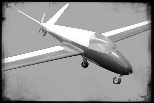
Around 1955, Walter Horten was interested in developing a long-distance drive for his flying wing aircraft. He commissioned Prof. Karl Lürenbaum ‘s Institute for Engine Dynamics at RWTH Aachen University to develop a suitable engine. Walter Horten commissioned his childhood friend Alfons Pützer to build a suitable test vehicle for long-distance wave testing. Pützer suggested using a Fritz Raab Doppelraab design, which had already been used in the Pützer Motorraab.
Pützer then commissioned Fritz Raab to modify a Doppelraab 6, in which a small engine was placed in the center of gravity behind the pilot’s seat. The tailplane of the Doppelraab was replaced by an endplate tailplane with two fins, in the middle of which a pusher propeller was placed at the rear of the aircraft. The two-cylinder, two-stroke engine Hansa-Lloyd with 400 cm³ displacement and 12 hp drove the propeller at the rear via the long-distance shaft developed by Karl Lürenbaum. The test vehicle was created by Alfons Pützer KG in Bonn.
In December 1956, the Pützer Dohle took off on its maiden flight in Bonn-Hangelar. The air sports club in Bonn received the jackdaw in early 1957 for its training operations to test in continuous operation. There were several disturbances in the area of the long-distance wave. The propeller, which had little ground clearance at the rear, was also damaged several times.
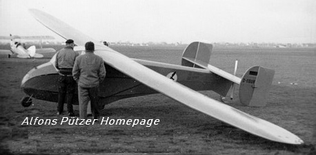
By arranging the engine in the center of gravity of the aircraft and the pusher propeller at the rear, the fundamentally good gliding characteristics of the Doppelraab were retained with the Dohle. Alfons Pützer then developed the jackdaw as a motor glider. He replaced the weak and too heavy Hansa engine with an Ilo F2x376 with 30 hp, with which the Dohle II should be able to self-launch. The small 14 kg fuel tank was replaced by a 40 kg fuel tank for longer cruising flights. This allowed the Dohle II to remain in the air for up to five hours. To protect the rear propeller from touching the ground, the Dohle II was fitted with a spur wedge at the rear.
The Dohle II was created in 1957 by converting the Dohle I at Alfons Pützer KG. It took off on September 2, 1957 in Bonn-Hangelar with the provisional approval D-EGUB for its first flight under its own power. In 1957, the Dohle II was one of the first usable motor glider constructions in Germany. However, Alfons Pützer had to stop further testing a short time later, since the start of series production of the Pützer Elster in the winter of 1957/58 occupied all capacities at Alfons Pützer KG.
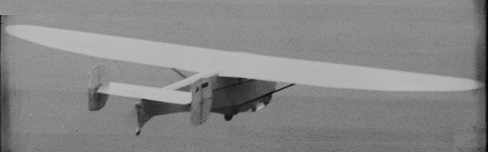
The basic structure of the Dohle II was later the starting point for the development of the Pützer Bussard trainer aircraft , which was also to be equipped with a pusher propeller at the rear in order to achieve jet-like behavior. The first drafts of the buzzard show a completely redesigned fuselage and low-lying wings. As with the Dohle II, however, the terminal plate tail unit with wedge spur was used. This tail was later replaced by a V-tail on the Bussard.
Only after the successful start of Elster production did Alfons Pützer take up the development of a motor glider again at the end of 1958. Drafts from this period show a further developed jackdaw with the V-tail already used in the Bussard and a low-lying wing. From 1959, however, Alfons Pützer gave up further development of the Dohle in favor of the completely new Pützer MS-60 motor glider design. The Dohle II was shut down in 1960.
Jackdaw I
Engine: 1 × Hansa-Lloyd, 12 hp
Wingspan: 13.20 m
Wing area: 18.00 m²
Aspect ratio: 9.7
Length: 7.20 m
Height: 2.00 m
Empty weight: 300kg
Maximum take-off weight: 420kg
Payload: 120kg
Crew: 1
Jackdaw II
Engine: 1 × Ilo F2x376, 30 hp
Wingspan: 13.20 m
Wing area: 18.00 m²
Aspect ratio: 9.7
Length: 7.20 m
Height: 2.00 m
Crew: 1
Empty weight: 325kg
Maximum take-off weight: 450kg
Payload: 125kg
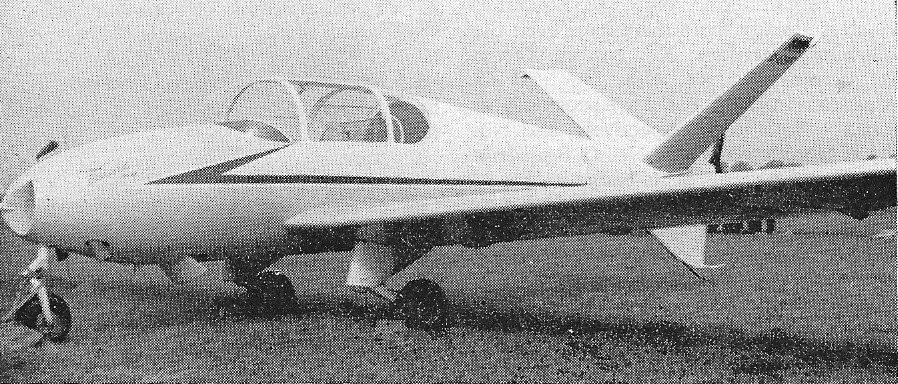
In the mid-1950s, the German Air Force showed interest in an inexpensive training aircraft for their budding jet pilots. Based on his experiences with the Pützer Dohle, Alfons Pützer suggested a propeller-driven piston aircraft for this purpose, the pusher propeller of which was arranged at the rear of the aircraft between a double tail unit.
Alfons Pützer and Karl Lürenbaum had already tested a long-distance shaft between the engine located in the fuselage and the propeller located at the stern as part of the Pützer Dohle, which, however, had only delivered unsatisfactory results. Karl Lürenbaum therefore applied to the Ministry of Economics and Transport for the Institute for Engine Dynamics at the RWTH Aachen for funds to further develop existing long-distance wave concepts under the project name SR-57. The research project also included the construction of a test vehicle for the drive, which Alfons Pützer KG operated under the name Pützer Bussard. Originally, Alfons Pützer saw a design similar to that of the Fouga Magister jet trainer for this test vehicle with two seats arranged next to each other and a low-wing construction, which had the double tail unit known from the Pützer Dohle in the rear area and a fuselage wedge to protect the propeller arranged at the rear. However, due to the power loss observed in the Pützer Dohle due to turbulence in the rear propeller, Walter Horten suggested using a V-tail instead of the twin tail of the Dohle. For the first time, Pützer also envisaged a retractable undercarriage for the Buzzard. The Continental C90-12F drive known from the Pützer Elster was used as the engine.
Problems were caused by the 6-metre-long remote shaft running through the entire hull, which showed frequent failure of dynamic components on the remote shaft test bench in Aachen and whose vibration behavior only showed satisfactory results after a complete redesign in the form of a three-part shaft.
In January 1959, the drive was installed in the test vehicle in Bonn. The German Research Institute for Aviation (DVL) in Cologne-Wahn was commissioned to test the test vehicle. There the Pützer Bussard took off for its maiden flight in February 1959 with provisional traffic approval D-EHIV. During the subsequent testing, the Pützer Bussard showed satisfactory results at the DVL up to the end of 1959, especially in the take-off and landing phase.
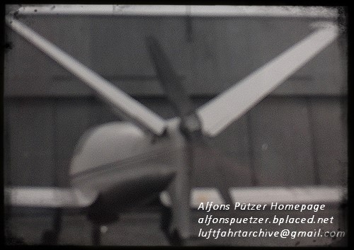
After the introduction of the Fouga Magister jet trainer, the German Air Force changed its training concept for its jet pilots. In the new training concept, the use of inexpensive upward trainers was no longer provided. Despite the positive testing, the Luftwaffe was no longer interested in purchasing the Pützer Buzzard in 1959. With the end of the SR-57 project, the test vehicle was shut down in the fall of 1959.
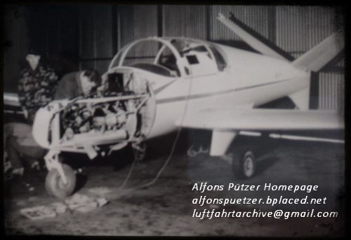
Erich Ufer has been working at Bölkow GmbH in Nabern since 1956 on the development of ring tail units. As part of this development, Bölkow GmbH planned to build the Bölkow P.103 test vehicle. After Ludwig Bölkowand Erich Ufer had not received any funding from state programs for the test vehicle by 1959, Alfons Pützer suggested converting the Bussard long-distance test vehicle that was no longer required to accommodate a ring tail unit. Apart from the redesign of the entire tail unit area with the ring manufactured by Bölkow in GRP construction, the Pützer Bussard received a new landing gear, also designed by Bölkow as part of the P.103, which ensured the necessary ground clearance for the ring tail unit. Due to the high weight of the ring tail, Alfons Pützer exchanged the Continental C90 engine for a 145 hp Continental O300, for which Karl Lürenbaum made the necessary changes to the remote shaft in Aachen.
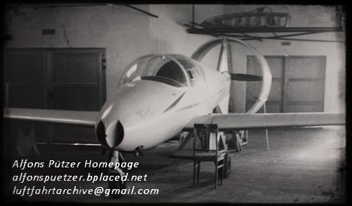
After completion of the model tests in the wind tunnel in Stuttgart, the conversion of the Pützer Buzzard took place until the end of 1960, which was then given the designation SR-57-2K. In order to gain further experience with the ring tail, before the first flight in early 1961 another wind tunnel program was carried out, in which the finished prototype was examined aerodynamically. On July 12, 1961, the first flight of the Pützer Bussard with a ring tail took place in Bonn-Hangelar. Satisfactory results were demonstrated in a three-month flight test. On March 22, 1963, the Federal Aviation Authority issued a provisional license for the ring tail carrier SR-57-2K. With the submission of the final report in June 1964, the test vehicle was shut down again.
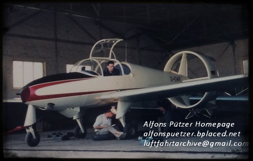
After completing the ring tail testing, the Pützer Bussard came to Karl Lürenbaum’s Institute for Engine Dynamics in Aachen. Together with the Rhein-Flugzeugbau RF-1 developed by Hanno Fischer at Rhein-Flugzeugbau, the Buzzard was used in ground and test bench tests in Aachen to develop turbofan engines, such as those used for the first time in 1968 on the motor glider Rhein-Flugzeugbau Sirius. The Pützer Bussard was largely dismantled during these tests and was later stored in Merzbrück near Aachen.
Walter Horten took over the dismantled Pützer Bussard in 1971. With the support of the Oskar Ursinus Vereinigung (OAV), Horten replaced the annular tail unit with a conventional tail unit and removed the long-distance shaft. Instead, the engine located in the bow was connected to a bow propeller of conventional design. Wings, landing gear and center fuselage with cockpit remained unchanged.
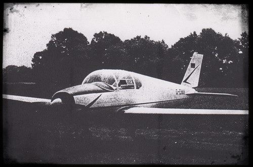
The Pützer Bussard was probably used in this configuration by the OAV for a number of years as a touring aircraft. It is said to have been destroyed later in a fire.
SR-57 (V-tail)
Engine: 1 × 70kW Continental C90-12F
Wingspan: 12.00 m
Wing area: 18.00 m²
Length: 6.30 m
Height: 2.20 m
Empty weight: 600kg
Maximum take-off weight: 760kg
Cruising speed: 180km/h
Crew: 1
Passengers: 1
SR-57-2k (Ring Tail)
Engine: 1 × 145hp Continental O300
Wingspan: 12.00 m
Wing area: 18.00 m²
Maximum take-off weight: 840kg
Crew: 1
Passengers: 1


