Rider San Francisco I

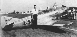
Bob Hall’s “Gee Bee” racers had dominated the 1931 Nationals. Behind Hall, at 237.738, was Ray Moore in the silver Rider No. 131, San Francisco I NR51Y, built by West Coast engineer Keith Rider and powered by a 6-cylinder, 160-hp Menasco in-line engine.

During a minor event in the 1931 Nationals, Moore had placed second to the Gee Bee Z and had actually beaten Wedell’s Wedell-Williams. That year, the Rider and Moore came in just 25 seconds behind Gehlbach.
It burned when the gas tank exploded on the ground in 1933. Salvage was sold to Roger Don Rae, who rebuilt it as 1934 Suzy (p: Roger Don Rae, Rudy Kling), it was a money-maker until it crashed on landing in 1936.

Engine: 200hp Menasco B-6S/C-6S
Wingspan: 21’4″
Length: 19’0″
Speed: 238 mph
Seats: 1

Riddle Airlines Inc

USA
Operator of a large fleet of Curtiss C-46 twin-engine transports, Riddle produced a modification kit in the mid-1950s which added 40mph (64kmh) to cruising speed and 2,204 lb (1,000 kg) to the payload. The improved model was designated C-46R, and Riddle subsequently converted its own fleet of 32 to have 2,100 hp Pratt & Whitney engines.

Richter Ric-Jet 4

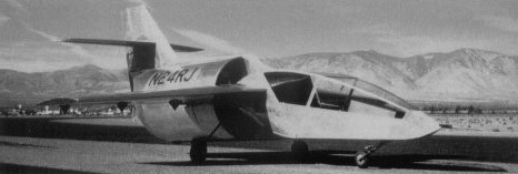
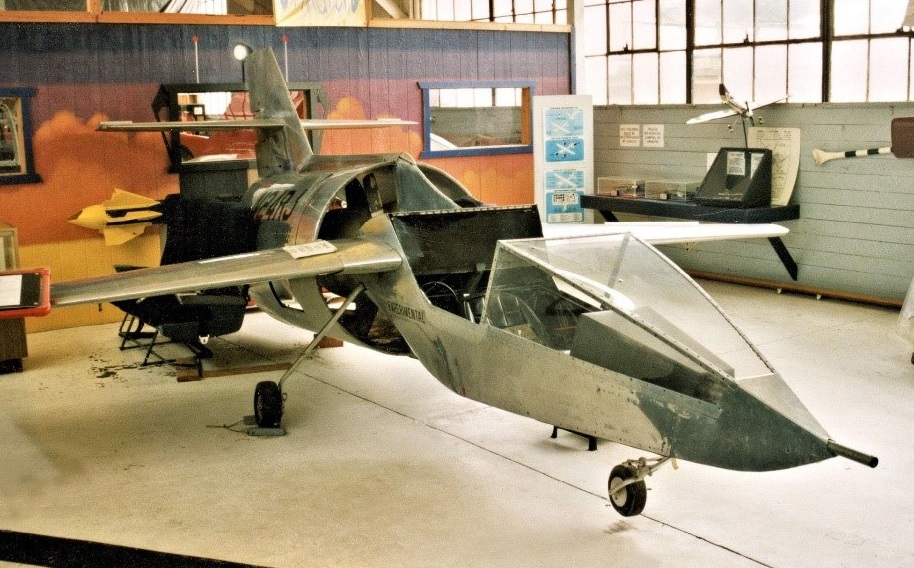
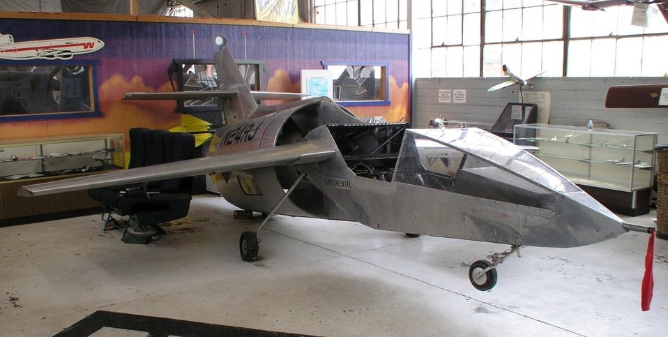
George Richter drew from his extensive experience as a modeler and a series of sub-scale models were built to try out different plan forms. The Ric Jet 4 was based upon Richter’s interpretation of the results of the model series. By July, 1973, the basic framework of the Ric Jet 4 was complete and on the gear. Engine placement and skinning followed as time and finances allowed. The finished product was an aircraft with a polished aluminum finish marred slightly by inexplicable patching and fairing of gaps with aluminum duct tape.

The Ric Jet 4 was never well publicized in the 70’s and many of its features have been garbled by word of mouth. In the spring of 1975 vague rumors of a jet-like all-aluminum aircraft making low altitude tests at Mojave Airport, California began to surface.

By 1980, the Ric Jet 4 had been retired to the Chino Air Museum and had sunk back into obscurity. It was not a successful project overall, but Richter’s layout showed a good understanding of the differences between ducted fan aircraft and turbojets. His fan or “contained propeller”, incorporating an unusually large gap between the fan tip and the inner wall of the duct, seemed heretical to formally trained designers.

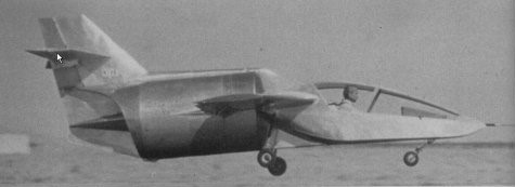
The Ric Jet 4 gives the appearance of a single-seat sailplane pod melded with an aluminum barrel, a mid-wing and high cruciform tail. The landing gear is tricycle and fixed. The intake into the large diameter duct is carefully faired at the back of the pod, but the lips of the duct lack the inner radiused edges or bell-mouth usually found in ducted fans with high static thrust. A large engine access hatch is present on the starboard side of the duct allowing inspection and maintenance of the engine and fan via hinged panels in the centerline pod.

The fan unit consists of a tractor-mounted Mazda RX-2 automobile engine direct-driving a two-bladed 40 in (1.02 m) diameter wood propeller via an aluminum extension shaft replacing the original engine flywheel. A nicely streamlined pod encloses the engine and muffler, The propulsion package is supported concentrically by struts which incorporate flow straighteners aft of the propeller and provides vertical structural connections with the tail unit, a function that the after spar of the wing provides on the horizontal axis. To help in balancing the loaded aircraft, a battery box was located in the extreme nose forward of the instrument panel.

The wings have marked sweep back and anhedral, and incorporate full span slotted flaps. Spoilers are substituted for ailerons. The wings fold upward at their junction with the duct for hangarage and ground transport on a trailer. They are fabricated like the rest of the airframe from pop-riveted aluminum tube, channel and sheet.

The engine was located directly on the CG and overall stability of the aircraft was deemed acceptable. A pad was provided at the bottom rear of the duct as the aircraft rocked back when the pilot exited the cockpit.

Registered N24RJ cn 001, trial flights in ground effect were useful in confirming several of the Ric Jet’s features. The spoilers worked well for lateral control. The aircraft’s split rudder and large swept fixed surface fairing into a ventral strake was apparently large enough to ensure good low speed control in yaw. Wheel shimmy was eliminated and alignment of the landing gear was corrected. General ground handling characteristics were good.

It was assumed that further trials would resume when a more powerful engine and a new propeller became available. It never happened, the aircraft sat for years, then was donated to the Chino Air Museum in the early 1980’s.”

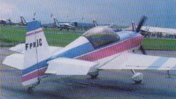
Richet Cobra 202

Richet revised the Cobra 200 of Yves Debordes and was selling the Cobra 202 in kit form via Sté Aéro-Composite of Saujon circa 1998. The wings are carbonfibre and the fuselage is of composite/foam construction.

Engine: AEIO-360, 200 hp
Wing span: 7.5 m
Wing area: 10.5 sq.m
MAUW: 770 kg
Empty weight: 520 kg
Fuel capacity: 160 lt
Max speed: 290 kph
Cruise speed: 270 kph
Minimum speed: 95 kph
Seats: 2

Richard TOM-1

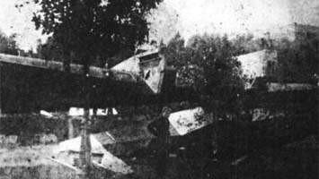
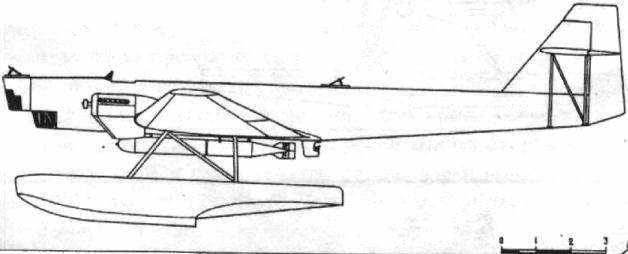
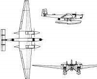
During his years in the USSR, French aircraft builder Paul Aimé Richard designed and built the Richard TOM-1 (Russian: Ришар ТОМ-1) Naval float bomber and torpedo boat. Only one prototype was built that was not produced due to the introduction of a navalized version of the Tupolev TB-1 with similar features and capabilities, but cheaper and easier to build.

The projecting task of the Open Sea Torpedo Boat or TOM was assigned to the KB led by Richard in late 1928. Several Soviet engineers participated in its development, who would soon achieve international renown for their creations. Notable among them were: II Artamonov, DM Jomnski, D. Samsonov, SA Lavochkin, IV Ostoslavski, MP Mogilievski, AL Gimmelfarb, GS Yelenievski, ZI Zhurbin, NI Kamov, MI Gurevich, SP Koroliov, IV Chetverikov, NK Skrzhinski, GM Beriev, IA Berlin, DA Mikhailov, VB Shavrov, GM Mozharovski, among others.

The TOM-1 was envisioned as a large monoplane of all-metal construction with floats. All the coating was made with smooth duralumin sheets of 0.5 – 0.6 mm, which gave it good aerodynamics. The structure was also designed entirely in duralumin, which was uncharacteristic of Soviet aircraft construction for those years.

The very thick wing with a 33 meter span had a rectangular midplane that was joined to consoles with a trapezoidal shape in the plane and marked narrowing towards the ends. The wing had a Sen-Sir-60 profile, with two skeletal spars and laminated ribs with large circular and oval holes to reduce weight. These ribs were located at a distance of 0.4 meters (quite compact for Soviet standards of the time). The segments of the stringer structure were achieved by joining two grooved pieces to form a kind of rectangular tube. Louvred flaps, capable of tilting downward at 40º angles, were located along the entire span of the trailing edge on the consoles.

The fuselage was a monocoque structure with the frames every 0.4 meters. The stringers were located every 150 mm, both in the fuselage and in the floats.

The tail unit was located high with triple empennage and was braced by means of N-pillars. The tail rudders incorporated trimmers to reduce the effort on the controls.

The large floats were fixed to the fuselage by means of 4 struts with tensioners between them.

The whole construction of the TOM-1 was quite light and very strong, but it was very technically demanding and expensive, almost twice that of the similar TB-1, and required a great deal of expensive sheets of duralumin, of which a considerable part was lost when drilling to reduce weight.

The two 680 hp BMW VI engines located on the wings.

The armament consisted of three firing points with PV-1 machine guns. These points were located fore and aft and a third in a retractable turret located in the lower section of the fuselage.

In the ventral zone, between the floats, one or two torpedoes could be fixed, developed by the OsTex Byuró.

The model was developed by the workshops located in the same KB building. On July 3, 1929 the project was completed and signed by PA Richard, his deputy DM Jomski and specialist SA Lavochkin.

In the fall of 1930, the plane was built and on January 1, 1931 it was transferred to Sevastopol for testing.

Assembly and preparation for testing were extremely lengthy. The plane was only ready in August. During the tests, carried out by pilot NI Kamkin with NI Kamov as engineer in charge, the aircraft presented acceptable performance. However, the new torpedo bomber was similar in capacity and performance to the TB-1 bomber and Tupolev was already successfully projecting a navalized version of this giant known as the ANT-4P. Building a similar plane, expensive and developed with unusual materials, was considered little objective. Only the prototype was built.

In 1931 Richard left the USSR due to the lack of new orders.

TOM-1
Engines: 2 x 680 hp BMW VI
Wingspan: 38.00 m
Length: 19.95m
Wing area: 120.00 sq.m
Empty weight: 5255 kg
Normal takeoff weight: 8030 kg
Top speed: 210km/h
Cruising speed: 182 km/h
Practical ceiling: 5500 m
Armament: 3 x 7.62mm PV-1 machine guns
Bombload: 1000 kg of bombs or two torpedoes
Accommodation: 4-5
Richard Commuter

The Commuter, a high-wing cabin monoplane, features all metal construction with no complicated double-curvature skin panels. The two-place taildragger carries 125- to 150-hp Lycoming powerplants. Persons sit in side-by-side fashion.

Wingspan 25’
Length 19’9”
Gross Wt. 1500 lb
Empty Wt. 805 lb
Fuel capacity 50 USG
Top speed 150 mph
Cruise 140 mph
Stall 40 mph
Climb rate 900 fpm
Takeoff run 1200 ft
Landing roll 1500 ft
Range 900 sm