Warsztaty Szybowcowe Wrona (Crow) / Kocjan Wrona

Wrona bis

The Warsztaty Szybowcowe Wrona (Glider Workshops Crow), or Kocjan Wrona after its designer, was the most numerous and widely used Polish pre-war primary glider.

Designed by Antoni Kocjan, the Wrona was in competition with the Czerwiński and Jaworski CWJ flown in 1931. Both were simple, high-wing and open frame (flat, uncovered girder fuselage) gliders in the style of the earlier German Zögling. With LOPP funding five pre-production airframes were built by Warsztaty Szybowcowe, the first flying from Mokotów on 6 September 1932.

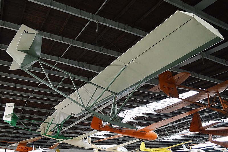
Its two-part wing, mounted on top of the fuselage, was rectangular in plan and built around two spars. It was plywood-covered ahead of the forward spar, forming a torsion-resistant D-box, with the rest fabric-covered. On each side a pair of parallel struts braced the spars to the lower fuselage. Long, rectangular ailerons reached from strut to tip.

The upper and lower longerons or chords of the open-frame fuselage were joined together with vertical and diagonal braces. The pilot sat, unprotected, under the wing leading edge on a seat on the forward vertical brace. Aft, the Wrona’s triangular fin extended above and between the longerons and carried a tall, nearly rectangular rudder which reached down to the lower longeron. Its narrow, triangular tailplane, mounted on the upper longeron, carried rectangular elevators with a deep cut-out for rudder movement. Fixed tail surfaces were ply-covered and the control surfaces fabric-covered. Wronas landed on a tandem pair of sprung skids on the lower longeron.
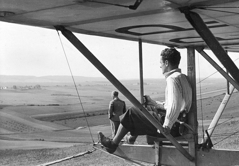
The early Wronas had a wing with a span of 8.8 m (28 ft 10 in) and area of 13.2 m2 (142 sq ft) but by 1934 the revised Worna bis had span and area increased by about 5%. Extended exposure to novice pilots revealed a tendency to enter a spin at high angles of attack caused by over-sensitive elevators. Several proposed solutions were tested and in the later 1930s, the problem was successfully resolved when all Wrona bis had their elevator areas reduced, together with a tailplane of increased area set at a negative angle of incidence (-2º).

Wrona production began in 1933 and continued up to the Invasion of Poland in 1939, with about 100 built at Kocjan’s Warsztaty Szybowcowe factory and another 250 built under licence in at least seven other European countries. Construction drawings, materials and parts were sold, with at least 50 aircraft built by clubs and similar organizations.

It is not surprising that a basic trainer set no major records; but in June 1938, a Wrona bis made a 6.5 km (4.0 mi; 3.5 nmi) cross-country flight, a first (and last) record for an open girder glider in Poland. In April 1935 another, accompanied by a Warsztaty Lotnicze Czajka, made the first winch launchings in the country.

Only one or two survived the war. One Wrona bis remained in use until 1950, after which it became a museum exhibit. In December 1963 it was acquired by the Polish Aviation Museum in Krakow, where it remains on display.

Variants:

Wrona
Prototypes and 1933 production variant.

Wrona bis
Superseded Wrona in 1934 production with a wing of greater span and area. Modified in the late 1930s to overcome over-sensitive elevators and associated spinning tendencies.
Wingspan: 9.31 m (30 ft 7 in)
Wing area: 13.9 m2 (150 sq ft)
Length: 5.6 m (18 ft 4 in)
Height: 1.9 m (6 ft 3 in)
Empty weight: 75 kg (165 lb)
Gross weight: 150 kg (331 lb)
Maximum glide ratio: 11 at 50 km/h (31 mph; 27 kn)
Rate of sink: 1.2 m/s (240 ft/min) at 48 km/h (30 mph; 26 kn)
Minimum speed: 45 km/h (28 mph; 24 kn)
Capacity: One
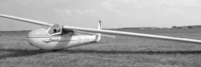
Warsztaty Szybowcowe Orlik / XTG-7

Orlik 2

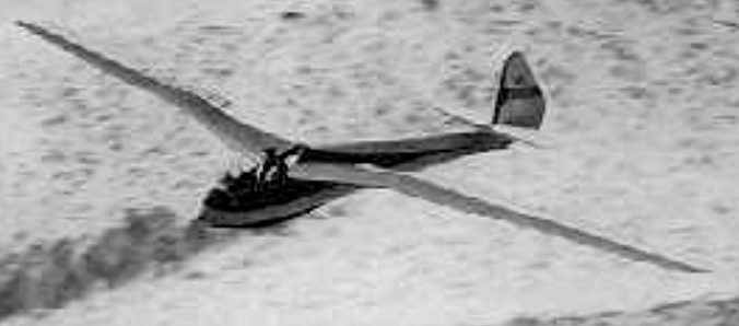
Designed by Antoni Kocjan, the Orlik 2, which first flew in 1938, was a development of the 1937 14.4 m. Orlik 1. A special model (Orlik 3) was developed for the Olympic design competition for the 1940 games (won by the German D.F.S. Meise). It has unusual airbrakes on the wing undersurface, close to the leading edge, from the root to the wing bend.

Orlik 2

One example came to the U.S., and in WWII was imposed into the military as the XTG-7. Later, flown by Paul MacCready, it briefly held the world altitude record in 1948 at over 9,000 m. in the Sierra wave as well as winning the 1948 and 1949 U.S. Nationals.
Structure: Wood/ fabric wing and tail, wood fuselage.

Orlik 2 / XTG-7
Wing span: 15m / 49.2ft
Wing area: 14.8 sq.m / 162.5 sq.ft
Aspect ratio: 15.2
Empty Weight: 160 kg / 353 lb
Payload: 85 kg / 187 lb
Gross Weight: 245 kg / 540 lb
Wing Load: 16.5 kg/sq.m / 3.32 lb/sq.ft
L/DMax: 24@ 71 kph / 38 kt / 44 mph
MinSink: 0.64 m/s / 2.1 fps / 1.24 kt
Seats: 1
No. Built: 18

Warrior Centaur

Considerations that influenced the layout of the Centaur concept included cabin volume, access, low take-off speed and boat handling duties.

The hull features no transverse step and no forebody chines. This hull accelerates to about seventy percent of take-off speed in displacement mode by which time the water is satisfactorily “hard” and aerodynamic lift takes more than half the weight of the aeroplane off the water. The Centaur encounters no drag hump. This leaves much more thrust available than conventional seaplanes for getting more useful load airborne in a respectable distance. This useful load advantage is further increased by the reduced structural content and weight in the hull, having typically half the beam and surface area of conventional seaplane hulls (floatplanes or flying boats).

The fine bow results in little rotation. Because of the narrow beam, any remaining rotation results in less rise, wave dispersion, spray and wasted energy. The Centaur can handle short steep waves typically twice the height tolerated by equivalent seaplanes.

With the composite vinylester-epoxy laminating resins primary structure largely inset from a secondary shell, the Centaur will tolerate abuse which also aids repair without specialist facilities.

The Centaur’s low stub-wing uses ground-effect aerodynamics to aid low take-off speed. This is helped by a continuous flap through the wing center-section which provides much lift in the propeller slip-stream.
The flap and wings create down-wash on the tail. This down-wash substantially balances the pitching effects of changes in power and flap setting.

Using engineering content near identical to the undercarriage, the outer wing panels can be released and folded back to within the beam of the sponsons, so that the Centaur can be berthed or tied up against the side of a dock or ship, or in marinas. In preparing for flight, as they rotate forward to the locked position, a central stub spar mates with the spar in the wing panel, thus completely removing bending forces from the hinge. The aircraft cannot be flown unless locking is successful and the wings cannot be unlocked unless taxiing at low speed on the surface.

Warrick 1910 Flying Machine

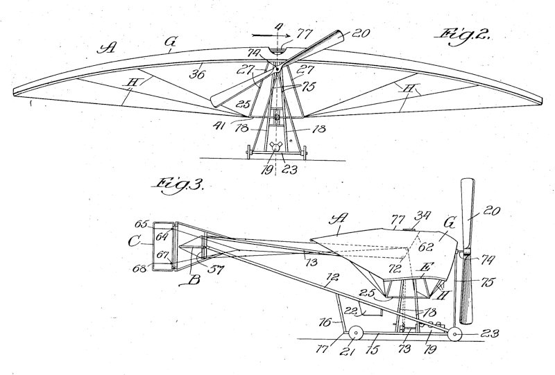
A shoulder-wing monoplane which John A. Warrick of Chicago applied a patent for in 1910 (granted in 1912), the intention being that it would “automatically maintain a proper equilibrium under all ordinary or normal conditions in flight”. This was achieved by a control system that, among other things, allowed the pilot to change the incidence of the somewhat parachute-like negative-dihedral wing. It’s not known if it was built.