Lilienthal, Otto

The most significant pre-Wright brothers aeronautical experimenter was the German glider pioneer Otto Lilienthal. In Germany, Otto Lilienthal make an intensive study of bird anatomy and flying characteristics, inspired by the storks which he and his brother Gustav watched wheel¬ing over the rooftops of Potsdam, their home town. He sought to discover precisely how birds flew, altering the dihedral angle of their wings for lateral stability, and varying the camber of the surfaces for lift or drag. Lilienthal was quick to appreciate the importance of curved wing surfaces. In 1889 he published the results of his findings in his book Der Vogelflug als Grundlage der Fliegekunst (Bird Flight as the Basis of the Flying Art), and set about testing his theories.
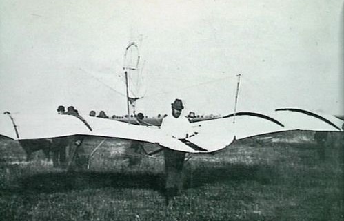
Otto Lilienthal Article

Between 1891 and 1896, he built and flew a series of highly successful full-size gliders. During this period, Lilienthal made close to 2,000 brief flights in 16 different designs based on aerodynamic research he conducted in the 1870s and 1880s. Most were monoplanes with stabilizing tail surfaces mounted at the rear. Control was achieved by shifting body weight fore-and-aft and from side-to-side.

Lilienthal began testing gliders in his backyard on a one metre platform and made hundreds of flights there before moving to a small hill, two and a half metres high.

By 1893 his gliders had cambred wings with radiated tip, fixed rear fin and tailplane, and could be folded to fit through an ordinary door.

On the evening of 9 August 1896, Otto was at Stöllen in the Rhinower Hills testing a new kind of head-movement control arrangement when a sudden gust upturned his No. 11 monoplane glider and he crashed heavily from 15 m (49 ft) breaking his spine. He died in a Berlin clinic the next day. His last words were ‘Opfer mussen gebracht werden’ (‘Sacrifices must be made’).

Gustav Lilienthal (1849-1933) was the younger brother of glider pioneer Otto Lilienthal. He spent the last 20 years of his life developing ornithopters, based on his studies of bird flight. The 1914 “Big Bird” spanned 17.5 metres and was tested at the research station of Altwarp, on the Stettiner Haff, but never left the ground. Lilienthal continued working at the Berlin Tempelhof and Adlershof airfields until his death.
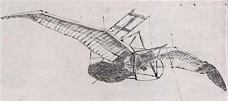
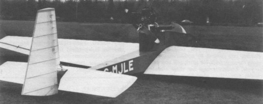
Gustav Lilienthal “Großer Vogel” (Germany, 1914)

Lightwing Rooster II

The Rooster2 is John Lee’s two seater and, although it looks totally different from the Rooster 1, it uses similar constructional techniques and materials, and its steering arrangements are also similar; braking, however, comes not from a nose skid but relies solely on the air resistance of the thick section wing. Along with its ‘boxy’ fuselage, the thick wing section (entirely a John Lee creation), the aircraft is fitted with a Robin EC44 engine which, because of the engine’s position, is mated to a smaller than ¬ideal prop. Conceived largely as a trainer, the Rooster 2 has a certain degree of flexibility built into its construction, to enable it to cope with bad landings by inexperienced pilots. The thick cantilever wing was chosen largely to simplify construction it eliminates the need for rigging wires. While the aircraft can be re rigged for trailer transport, portability is not a high priority. This aircraft does not in anyway pretend to be car toppable.
Tandem two seat single engined low wing with conventional three axis control. Wing has unswept leading edge, swept forward trailing edge and tapering chord; conventional tail. Pitch control by fully flying tail; yaw control by fully flying rudder; rod control by fully flying rudder; roll control by 40% span ailerons; control inputs through stick for pitch/roll and pedals for yaw. Cantilever wing; wing profile; 100% double surface. Undercarriage has two wheels with tailskid and nose-skid; no suspension on either wheel. No ground steering. No brakes. Wood fusel¬age, partially enclosed. Engine mounted above wing driving pusher propeller.

Engine: Robin EC44, 50hp at 6500rpm.
Propeller diameter 48 inch, 1.22 m.
Toothed belt reduction, ratio 2.0/1.
Max static thrust 180 lb, 82 kg.
Power per unit area 0.28hp/sq.ft, 3.0hp/sq.m.
Fuel capacity 13.2 US gal, 11.0 Imp gal, 50.0 litre.
Length overall 23.0 ft, 7.00 m.
Height overall 5.7ft, 1.75m.
Wing span 36.7ft, 11.20m.
Chord at root 6.0ft, 1.82 m.
Chord at tip 3.2ft, 0.97m.
Dihedral 2 deg.
Sweepback 0 deg.
Tailplane span 10.2 ft, 3.12 m.
Rudder height 5.1ft, 1.54m.
Total wing area 18. 1 sq.ft, 16.8 sq.m.
Total aileron area 12.9 sq.ft, 1.2 sq.m.
Rudder area 11.5 sq.ft, 1.07 sq.m.
Total elevator area 21.9 sq.ft 2.03 sq.m.
Wing aspect ratio 7.5/1.
Wheel track 6.6ft, 2.00m.
Main wheels diameter overall 11 inch, 28 cm.
Empty weight 3231b, 147kg.
Max take off weight 773 lb, 351 kg.
Payload 450 lb, 204 kg.
Max wing loading 4.27 lb/sq.ft, 20.9 kg/sq.m.
Max power loading 15.5 lb/hp, 7.0kg/hp.
Load factors +4.0, 2.0 design.
Max level speed 50 mph, 80 kph.
Never exceed speed 60 mph, 97kph.
Max cruising speed 50mph, 80kph.
Economic cruising speed 40 mph, 64 kph.
Stalling speed 25 mph, 40 kph.
Best glide ratio with power off 10/1 at 35 mph, 56 kph.
Take off distance 110ft, 35 m.
Landing dis¬tance 110 ft, 35 m.
Range at average cruising speed 100 mile, 161 km.

Lightwing Rooster I

Rooster I sailplane

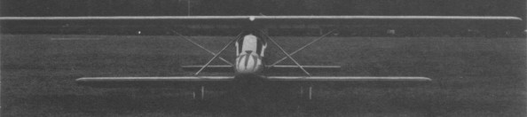
Single seat single engined biplane with con¬ventional three axis control. Wings have un¬swept leading and trailing edges, and constant chord; conventional tail. Pitch control by fully flying tail; yaw control by fin mounted rud¬der; roll control by two thirds span ailerons; control inputs through stick for pitch/roll and pedals for yaw. Wings braced by transverse struts; wing profile 100 % double surface. Undercarriage has two wheels with tailskid and nose-skid; no suspension on either wheel. No ground steering. No brakes. Wood/glass¬fibre fuselage, totally enclosed. Engine mounted between wings driving pusher prop¬eller.
Instead of alumi¬nium tube, Dacron and lots of rigging wires, he prefers simple traditional wooden construction, though as a concession to moderni¬ty the Rooster 1 does have a glass fibre nose.
The Rooster 1 was conceived in 1977 as a sailplane. As a sailplane it thermalled at 600 ft (185 m), was aero towed three times and made some 300 circuits. It also proved stronger than expected, landing without dam¬age across the furrows of a ploughed field.
Right from the start, however, John in¬tended to power the machine, simply because he wanted to go soaring without hordes of assistants. So once he was satisfied with the aircraft’s dynamic qualities, he fitted a Chrys¬ler engine. In 1982 he was replacing this with a Valmet unit. The undercarriage design uses only two wheels but has a skid at either end. The wheel track is large enough that the aircraft does not tip up when the pilot enters, yet narrow enough to permit ground man¬oeuvring using only the rudder. There are no wheel brakes; instead the pilot simply pushes forward the stick and lets the friction gener¬ated by the nose skid slow the aircraft.
There are no plans for manufacture, but depending on demand, John may produce plans for the aircraft.

Engine: Valmet, 10 hp at 6000 rpm.
Propeller diameter and pitch 52x27inch, 1.32×0.69m.
V belt reduction, ratio 4.0/1.
Power per unit area 0.07hp/sq.ft, 0.8 hp/sq.m.
Fuel capacity 6.6 US gal, 5.5 Imp gal, 25.0 litre.
Empty weight 320 lb, 145kg.
Max take off weight 570 lb, 259kg.
Payload 250 lb, 113kg.
Max wing loading: 3.99 lb/sq.ft, 19.5 kg/sq.m.
Max power loading 57.0 lb/hp, 25.9kg/hp.
Load factors +6.0, 4.0 design.
Length overall 17.9 ft, 5.45 m.
Height overall 4.9ft, 1.50m.
Wing span 30.2ft, 9.20m.
Constant chord 3.0ft, 0.91m (top wing).
Dihedral 0 deg
Sweepback 0 deg
Tailplane span 10.5 ft, 3.20 m.
Fin height 5.2 ft, 1.58 m.
Total wing area 143 sq.ft, 13.3 sq.m.
Total aileron area 13.2 sq.ft, 1.23 sq.m.
Fin area 4.6 sq.ft, 0.43 sq.m.
Rudder area 6.2 sq.ft, 0.58 sq.m.
Total elevator area 16.8 sq.ft, 1.56 sq.m.
Wing aspect ratio 10/1 (top wing).
Wheel track 6.2 ft, 1.88 m.
Main wheels diameter overall 11 inch, 28 cm.
Max level speed 65 mph, 105 kph.
Never exceed speed 75 mph, 121 kph.
Max cruising speed 60 mph, 97 kph.
Economic cruising speed 40 mph, 64 kph.
Stalling speed 30 mph, 48 kph.
Best glide ratio with power off 14/1 at 33 mph, 53 kph.
Range at average cruising speed 300 mile, 483 km.

Lightwing

1983: John Lee, Littleton Park Nursery, Laleham Road, Shepperton, Middlesex, Great Britain.
John Lee is one of Britain’s most prolific and individualistic homebuilders and since 1970 has built five aircraft, of which the two most recent (circa 1983), the Rooster 1 and Rooster 2 can be classified as microlights.

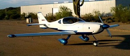
Lightning West Lightning

Lightning
Engine: Jabiru 3300, 120 hp
Maximum Speed: 190 mph
Cruise Speed: 175 mph
Vne: 208 mph
Stall (Full Flap): 45 mph
Stall Clean: 56 mph
Glide Ratio: 17:1
Take Off Roll: 315 ft.
Landing Roll (with brakes): 500 ft
Climb Rate (at gross): 1200 ft./min
Turn Rate 45/45°: <1 second
Maneuvering Speed: 140 mph
Endurance: 4 hr
Range w/ res: 700 sm

Lightning Sport 3300
Engine: Jabiru 3300, 120 hp
Maximum Speed: 150 mph
Cruise Speed: 138 mph
Vne: 208 mph
Stall (Full Flap): 40 mph
Stall Clean: 51 mph
Glide Ratio: 17:1
Take Off Roll: 275 ft.
Landing Roll (with brakes): 350 ft.
Climb Rate (at gross): 1800 ft./min.
Turn Rate 45/45°: <1 second
Maneuvering Speed: 140 mph
Endurance: 5 hr
Range w/ res: 700 sm

Lightning Bug Aircraft Lightning Bug / Reflex Fibreglass Works / RFW Lightning Bug / MaD Aviation Lightning Bug

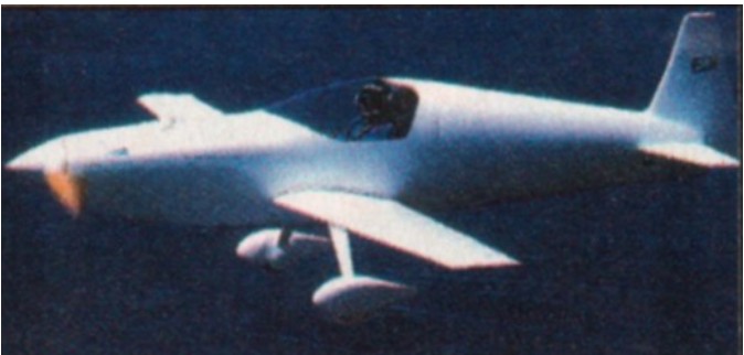
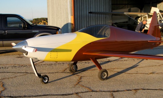
Designed by Howell C. “Nick” Jones Jr, single place composite. Aerobatics capable. The original production engine was the AMW808FIG.

In 2011, all rights, molds, tooling and spare parts inventory for the Lightning Bug was purchased by MaD Aviation LLC. An original Lightning Bug, N44XM is being re-engined with a 100hp Rotax 912ULS to test this engine/airframe combination with a view to making a new Lightning Bug kit available, using this reliable four stroke engine.

Engine: AMW808FIG, 100 hp.
Speed max: 250 mph.
Cruise: 225 mph.
Range: 800 sm.
Stall: 62 mph.
ROC: 1200 fpm.
Take-off dist: 800 ft.
Landing dist: 1000 ft.
Service ceiling: 20,000 ft.
Fuel cap: 23 USG.
Weight empty: 375 lbs.
Gross: 800 lbs.
Height: 5.08 ft.
Length: 17.46 ft.
Wing span: 17.83 ft.
Wing area: 40 sq.ft.
Seats: 1.
Landing gear: tail or nose, retractable wheel.

Light Miniature Aircraft LM-J3-W

LMA’s Piper Cub LM-J3-W is an exact, full scale, two place tandem replica in wood. It may be built to conform to the New LSA Rules, with a Rotax 65 hp 582 Engine or use up to and including a 65 HP Continental or equivalent. The Kit is a materials kit, but most of the metal parts are cut from Aluminum Extrusions, making fabrication very fast and inexpensive, with no welding (except for the Engine Mount).

All of the Light Miniature Aircraft Manuals, are approximately 200 pages. Each manual has step-by-step instructions, for each section of the plane, as well as figures, drawings and full size templates to guide the builder through the building process. Each manual also comes with a complete set of full size plans for the fuselage and tail feathers as well as full size templates for the wing ribs, landing gear and items such as the wind shield.
The wooden planes are constructed in the same manner.
Plans and manuals are still available for our metal planes, however, due to rising aluminum costs and availability problems, Light Miniature Aircraft no longer supply kits for the air frames of the metal planes. Some partial kits, for items like the controls or landing gear were still available.