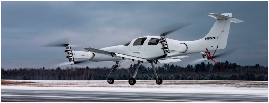
Beta Technologies flew their Ava XC technology demonstrator on 22 June 2018 with four contrarotating, tilting rotors mounted on the wing tips of a vehicle that resembles a fixed wing aircraft. As with demonstrators developed by other manufacturers, the Ava XC was developed to gain familiarity with eVTOL technology.
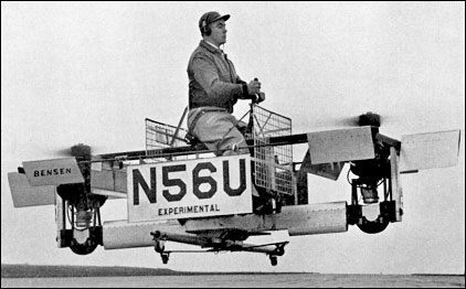
The Bensen B-10 Propcopter consisted of a boxy frame with 1.2 meter (4 foot) props mounted vertically on the front and back of the frame. Each was powered by its own 54 kW (72 HP) McCulloch engine. The Propcopter flew in 1959.
The B-10 was flown in prototype form (N56U) on 6 August 1958 and apparently was tricky to handle. It was not developed further.
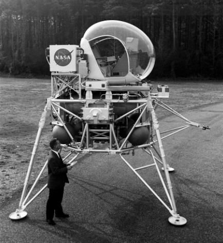
Lunar Landing Research Vehicle (LLRV) built in 1963 as part of the Apollo Project to land on the moon. It was a vertical take-off and landing vehicle powered by a single jet engine. The vehicle allowed Apollo astronauts to train for real moon landings.
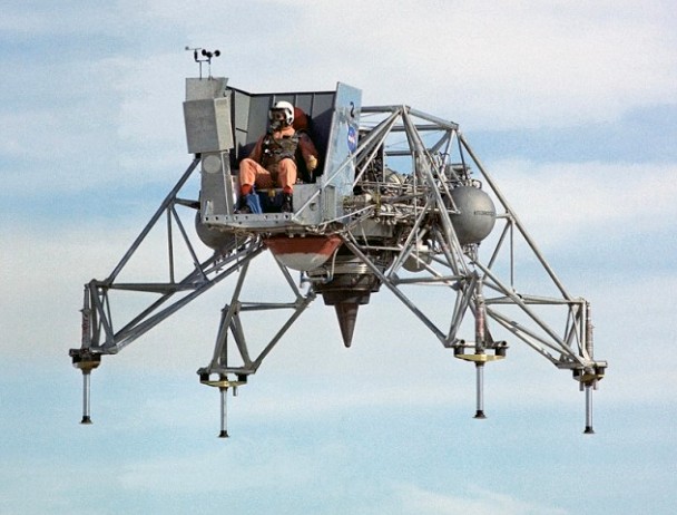
The Lunar Landing Training Vehicle (LLTV) was built by Bell Aerosystems in 1964 as part of the Apollo Project to land on the moon, it was a vertical take-off and landing vehicle powered by a single jet engine. The Lunar Landing Research Vehicle (LLRV) was built by Bell Aerosystems in 1964 as part of the Apollo Project to land on the moon, it was a vertical take-off and landing vehicle powered by a single jet engine.
By always offsetting five-sixths of earth’s gravity, the vertically mounted turbofan engine enabled the LLTV to reproduce the characteristics of landing a lunar module on the moon’s surface. The LLTV was used to train America’s Apollo astronauts.
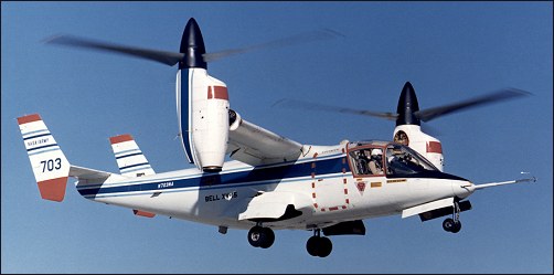
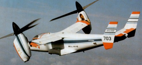
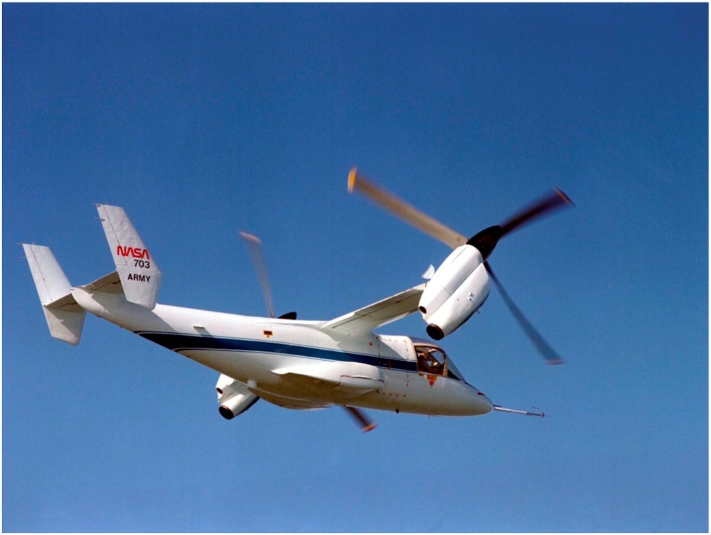
In 1965, the U.S. Army issued a Request for Proposal for what it called the Composite Aircraft Program. Composite, in this case, was for a vehicle that would have both helicopter and airplane characteristics, specifically, looking for a single aircraft to replace both the CH-47 helicopter and the C-7 “Caribou”. Three contractors were selected to perform design studies in 1966 and Lockheed and Bell were chosen to perform further exploratory definition studies, which were completed in September 1967. However, the Army dropped the development due to limited funds. Bell decided in 1968 to continue development for a proposed civil tilt-rotor aircraft, designated the Model 300. Initial work led to the design for a 4285kg aircraft powered by two Pratt & Whitney PT-6 engines powering 7.6m diameter rotors. One-fifth scale aerodynamic and aeroelastic models were built and tested extensively from 1969 through 1973. Full size rotor and rotating mechanisms were whirl tested to determine their hover performance and then tested in 1970 at the NASA Ames 12m x 24m wind tunnel at various rotation speeds, angles, and airspeeds up to the maximum tunnel speed of 370km/h. The rotor met or exceeded all performance and stability predictions. Then, in 1972, NASA and the U.S.Army Air Mobility Research and Development Laboratory jointly started the Tiltrotor Research Aircraft Program. Since the Tiltrotor Research Aircraft Program was to be strictly a research program and would not lead to the production of an operational aircraft, costs were to be kept under control by not making weight minimization a major factor and encouraging the use of off the shelf components. Advanced technologies like fly-by-wire and composite structures were to be avoided. Weight growth and performance shortfalls would be tolerated in order to minimize cost and schedule impacts. Even the number of aircraft to be built was a factor. The two aircraft option was selected because of the high accident rate experienced by most other VTOL research programs. Bell’s proposal started with the Model 300’s design and evolved it into Model 301. Bell kept the rotor and transmission, but replaced the engines with the more powerful Lycoming T-53 because of the requirement to hover with only one engine and the greater empty weight and useful loads required. Another benefit of the engine switch was that the T-53 already had an oil system that could operate with the engine pointed vertically, which had been developed for the CL-84 program. Bell’s proposal was submitted on January 22, 1973, and comprised 300 volumes weighing 350kg. Bell’s proposal was selected in April 1973. NASA awarded contract NAS2-7800 for $28 million for the final design, fabrication, and preliminary testing of two XV-15s on July 31. The total estimated cost of the six-year program was $45 million. The 12.8m long fuselage design was of a conventional aircraft, semi-monocoque, , and using light alloy material. There was no fuselage pressurization, and the structure was stressed from +3 to -0.5 G. The airframes were designed for minimum service lives of 1000 flight hours over five years. The tricycle landing gear came from the Canadair CL-84. It utilized Goodyear magnesium main and nose wheels, and Goodyear hydraulically operated magnesium/steel disc brakes. The full-swiveling nose wheel incorporated shimmy dampers and a centering device. It retracted into a bay forward of the cockpit. The main wheels retracted into external pods on each side of the fuselage. A switch on the main gear strut prevented inadvertent gear retraction and tilting of the pylons more than 30 degrees from vertical when the aircraft was on the ground. The landing gear was structurally designed to withstand a touchdown sink rate of 3m per second at full gross weight. A 14500kg/sq.m nitrogen gas system provided for emergency extension in the event of a hydraulic failure. The H-tail consists of a horizontal stabilizer with a vertical stabilizer on each tip. This configuration was selected to provide improved directional stability at and near zero yaw angles. Rockwell International’s Tulsa Division built the fuselage and tail units under subcontract. Two pilots sat side-by-side in Rockwell-Columbus LW-3B ejection seats, entering through a door on the right side of the cargo compartment. The flight deck was heated, ventilated, and air conditioned, but not the cargo compartment. The cabin could accommodate nine personnel if not filled with test equipment. The wing measures 9.75m across, has a constant chord measuring 1.6m, and a area of 15.7sq.m (one of the design requirements was that the XV-15 be able to fit in NASA Ames’ 12m x 24m wind tunnel, which influenced the wingspan and rotor size). It is swept forward 6.5 degrees, not for any futuristic aerodynamic reasons, but to insure there would be adequate clearance when the rotor blades flex in airplane mode. Wing dihedral is 2 degrees. Along the trailing edge, a flap measuring 1sq.m occupies the inboard third, and a flaperon measuring 1.85sq.m occupies the outer two thirds. The flaps can be deflected down to 75 degrees to help provide additional lift at low speeds. In hover, the flaps and flaperons deflect downward to reduce slipstream interference by the wing. The problems with the wing/rotor/pylon stability that plagued the XV-3 were eliminated by designing a very stiff wing and nacelle/wing attachment, and by placing the rotor hub as close to the wing as possible. Each wing holds two fuel bladders that form a single crashworthy fuel tank in each wing. Together they hold a total of 830 litres. The pump in each wing tank is powered from a different electrical system. In the event of a pump failure, both engines can feed from the same tank, or in the case of an engine failure, one engine can feed from both tanks. Cross feeds activate automatically in the event of a pump failure to assure uninterrupted fuel flow to both engines. In the event of a complete loss of electrical power to both pumps, the engine driven pumps still can maintain adequate fuel flow. An Avco Lycoming LTC1K-4K engine, a modified version of the standard T53-L-13B engine, is mounted at each wing tip. They are rated at 1250shp for continuous operation, 1401shp for 30 minutes, 1550shp for 10 minutes for take-off, and 1802shp for two minutes for emergency power. Power is transmitted from the engines to the rotors using a coupling gearbox and transmission, which reduce the engine speed of approximately 20000 revolutions per minute down to a rotor speed of about 565 revolutions per minute in hover. The three-bladed, semi-rigid rotors measure 7.6m in diameter and have a 36cm chord. They were made of stainless steel and have a large amount of twist. (In July 1979, Bell received a contract from Ames for preliminary design of a composite rotor blade that would offer improved performance and increased life expectancy, compared to the existing metal blades. A set eventually was tested, but did not work well.) There are no flapping hinges, but the rotors can flap forward or aft as much as 6 degrees. To assure power to both rotors in the event of an engine failure, a shaft that runs through the wing interconnects the two transmissions. As a result of the interconnect, both rotors turn when the first engine starts. In the event of a double engine failure, both rotors will autorotate at the same speed. The nacelle tilt can be varied from horizontal to 5 degrees aft of vertical. Interconnected double ballscrew actuators operate the tilt mechanism in each nacelle. This assures that both nacelles always will be at the same position. The interconnected drive shafts and redundant tilting mechanisms permit single engine operation and fail-operate tilt capability. The cockpit has dual controls and resembles a helicopter cockpit, including a collective stick. The flight controls are designed to permit single pilot operation from either seat. In airplane mode, the control columns and rudder pedals work conventionally. In hover mode, the stick functions as a cyclic pitch controller. The mechanical mixing unit does everything needed to convert the controls from the helicopter mode to the fixed wing mode. Control authority between helicopter and airplane mode is phased in as a function of the nacelle tilt angle. This includes changing the rotors from cyclic pitch control in vertical flight to constant speed control for fixed wing flight. In airplane mode, the collective lever can still be used as a power lever. Moving the collective lever causes the throttles on the center console to move. Two switches, mounted on the collective lever and operated by the pilot’s thumb, control the nacelle tilt angle. One pivots the nacelles from end to end in about 12 seconds and allows them to be stopped at any position. The other switch moves the nacelles between pre-selected angles of 0, 60, 75, and 90 degrees (relative to horizontal). To rotate the nacelles, electrical valves activate hydraulic motors. In the event of a complete electrical system failure, the pilot can manually open the valves using T-handles in the cockpit. This will drive the nacelles to the helicopter position. Sperry Rand built the original navigation/guidance system. A digital computer provides navigation and control information to the pilot using advanced mechanical and electronic displays. The Calspan Corporation of Buffalo NY designed the Stabilization Control Augmentation System to improve its flight characteristics. The XV-15 does not incorporate fly-by-wire. Ailerons, elevator, and rudder are hydraulically boosted with a triple hydraulic system. They remain active in all flight modes.
The XV-15’s empty weight is 4315kg with a vertical take off weight of 5865kg. This allows 495kg for instrumentation, 180kg for pilots, and 630kg of fuel, while leaving a few left over for growth. Original estimated performance included a maximum level speed of 610km/h, service ceiling of 8845m, and a range of 800km. None of these goals ever were achieved, but the XV-15 did achieve its primary objective of proving the practicality of the tilt rotor concept.
In April 1974, Rockwell International (Tulsa Division) received a contract for the construction of the fuselage and the tail assembly of the two XV-15 airframes. On 2 October, 1975, components of the first prototype were delivered to Bell Helicopter in Fort Worth where final assembly would be undertaken. Aircraft No.1 (c/n 00001, N702NA) was rolled out, at Arlington, on 22 October, 1976. Before tiedown dynamic tests simulating all flight modes, the XV-15 No.1 underwent an extensive integration checkout. Ground runs began in January 1977, and included 100 hours of system qualification tests on an elevated test stand in both the helicopter and airplane modes to demonstrate that the aircraft met final flight qualification requirements. The first hovering flight was performed on May 3, 1977, followed by hover and low speed evaluations. This short test effort consisted of only three hours of hovering during May. No problems that warranted corrections were uncovered. Following these flight tests, the transmissions and rotors were torn down, inspected and reassembled. Because of NASA’s insistence on full-scale wind tunnel tests before attempting a conversion, aircraft #1 was shipped by C-5A to NASA’s Ames Research Center in March 1978 for wind tunnel tests. These tests were conducted in the Ames 12m x 24m foot wind tunnel in May and June 1978. Twenty hours of tunnel tests were performed at airspeeds between 110 and 330km/h. Configurations consisted of the rotors in helicopter and airplane positions, and numerous intermediate positions that would be encountered during transition. No unusual characteristics were noted in any of the tests conducted. Following the wind tunnel tests, the #1 aircraft was torn down and refurbished at NASA Ames.
The second XV-15, #N703NA, was nearing completion. Since the program lacked funds to keep two aircraft on flight status, testing resumed with the #2 aircraft, beginning ground tests in August 1978 at Arlington. Numerous minor problems plagued the aircraft during these tests, including a stress corrosion crack in the left engine gearbox, a clutch misengagement, and foreign object damage within the transmission. It made its first hovering flight on April 23, 1979, with Ron Erhart and Dorman Cannon, Bell’s XV-15 project pilot, at the controls. Conversion tests soon began, starting by rotating the nacelles 5 degrees forward on 5 May 1979. Successive tests gradually rotated the nacelles closer to horizontal, until the first complete conversion was made on July 24, 1979. The XV-15 also achieved a forward speed of 295km/h on this 40 minute flight. On 21 April, 1980, No.2 prototype reached 485km/h at 2530m. In one year of testing, aircraft No.2 logged 40 hours flying.
The Navy became interested in the XV-15 and because of continuous funding shortfalls, the Naval Air Systems Command began providing funding in 1979 and 1980 to insure the XV-15 flight testing would proceed up through the completion of envelope expansion flights. In exchange, the Navy would be allowed to perform flight evaluations.
During the contractor test program, all potential failures were simulated in actual flight or on the ground. On December 5, 1979. an actual engine failure occurred when the turbine seized. The transmission interconnect system worked properly, and both rotors continued to turn as designed. The predicted speed of 555km/h true airspeed was demonstrated with maximum rated power at a 4880m density altitude in June 1980. The contractor flight test phase was completed in August 1980. The basic conversion corridor and airspeed/altitude envelope up to 16,000 feet was demonstrated. About 100 full conversions were made. Some resonance problems were uncovered, as is normal in any helicopter development, but they were fixed quickly. Upon completion of the contractor flights, XV-15 #2 was shipped to NASA’s Dryden Flight Research Center for continued testing, where it was joined by aircraft #1. Both XV-15s then operated at Dryden for a short period. XV-15 #1 returned to Bell in September 1981. Flight testing by both NASA and Bell continued into the 1980s, and the two XV-15s proved to be virtually free of any significant problems. Additional accomplishments that were demonstrated included:
1.7 hour cruise endurance in airplane mode.
Cruise speed of 425km/h.
Take off as helicopter, fly twice as fast as a helicopter, and deliver payloads on half the amount of fuel when traveling distances of greater than 185km.
Autorotation descents in helicopter mode, but never to a full touchdown.
STOL take-offs with the nacelles tilted between 60 and 70 degrees, at the maximum gross weight of 6765kg. For taxiing on wheels, it was found that tilting the nacelles forward of vertical only 1 degree was enough to start the XV-15 moving forward. Tilting the nacelles aft of vertical brings the aircraft to a quick stop. The XV-15 tends to rock a bit more than other aircraft because of the weight of the engines and props all the way out at the wing tips. In hover, roll control is provided by differential rotor collective pitch, pitch control by cyclic pitch, and yaw by differential cyclic pitch. For maneuvering in the hover mode, many of the maneuvers normally performed by moving the cyclic control are done by tilting the nacelles. A combination of rotor angle and cyclic pitch also is used to vary the pitch attitude without moving forward. By tilting the rotors forward and simultaneously putting in aft cyclic control, the nose will pitch down, giving improved visibility over the nose. Vertical liftoff is very easy, as the XV-15 holds attitude on liftoff. Lateral movement is accomplished by banking slightly so that the thrust has a small side component. The XV-15 can travel sideways at 65km/h with no tendency to turn into the wind. It can hover backwards up to 65km/h. Touchdown surfaces can have an uphill or downhill slant of up to 15 degrees. Single engine performance is relatively poor, with single engine hover possible under only a very few conditions. During conversion from hover to conventional flight, there is a tendency to lose lift and sink, requiring the pilot to add power, but this is normal on all VTOL aircraft. With the nose up and full aft stick, level stalls in the clean configuration give a slight vibration at 205km/h. The aircraft will begin to sink, but there is no wing drop or other bad effects. In helicopter autorotation mode, the best descent rate of 11m/s is achieved at 140km/h. At 165km/h, the descent rate increases to 20m/s. For final approaches, pilots use nacelle tilt angle instead of pitch inputs to control airspeed. The 630kg of fuel contained in the wings proved to allow for only about a 280km range. An auxiliary tank holding an additional 405kg eventually was added to the fuselage, which increased the range to about 520km. In March 1982, aircraft #1 made a demonstration tour of East Coast facilities, which included seven flight demonstrations at six different locations in eight days. One flight included a stop at the helipad at the Pentagon. While on the tour, the XV-15 flew 4815km and needed only routine daily preflight maintenance. Following this East Coast tour, #1 was modified at Bell’s Arlington facility to perform an electronics mission evaluation. Items added included an APR-39 radar warning system and chaff dispenser system. The aircraft departed for NAS China Lake in California in May, then on to Ft. Huachuca in Arizona in June, and finally on to San Diego for sea trials. Shipboard evaluations were performed aboard the amphibious assault ship USS “Tripoli” off the San Diego coast in July 1982. Fifty-four vertical landings and take-offs (of which five were STOL take-offs) were performed. Other mission related evaluations included over-water rescue and simulated cargo lifting, which were demonstrated in May 1983, and simulated air-to-air refueling, which was performed in September 1984. By 1986, both aircraft had accumulated a total of 530 flight hours, made 1500 transitions, and reached an altitude of 6860m (while still maintaining an 4m/s climb capability). In March 1990, #1 set numerous time to climb and sustained altitude records for this class of aircraft. These included a climb to 3000m in 4.4 minutes and to 6000m in 8.46 minutes, without even performing extensive climb tests to develop an optimal climb profile. It also sustained an altitude of 6860m with a dummy payload of 990kg in addition to more than 450kg of test instrumentation. Under the new JVX programme Joint Services Advanced Vertical Lift Aircraft Program) the XV-15 served as test-bed. In direct relation to the JVX programme, XV-15 No.1 was tested in Fort Huachuca to evaluate its ability to accomplish SEMA missions (Special Electronics Mission Aircraft); the aircraft was sent to China Lake to measure its radar signature and, on 2-5 August, 1982, off San Diego, Lieut-Cdr John Ball and Dorman Cannon conducted the initial shipboard evaluation on board the amphibious assault ship USS Tripoli (LPH-10). This evaluation included vertical and short rolling take-offs, hovering flights and vertical landings. On this occasion, one of the 54 XV-15 landings was the ship’s 60.000th. The aircraft was then sent back to Fort Worth to undergo a complete overhaul and to receive several modifications. By the end of August 1982, the two prototypes had logged 289 hours of flight testing. The two XV-15s were then used in a research programme to explore the limits of the operational flight envelope and assess its application to military and civil transport needs. Late in 1987, the XV-15, piloted by Dorman Cannon and Don Borge, demonstrated its capabilities in the civil transport role at Washington and Chicago. The Chicago demonstration was conducted from Miegs Field in the very heart of the city. As of June 1990, XV-15 #1 was based at Bell Helicopter’s Flight Research Center in Arlington, TX, for continuing engineering development. XV-15 #2 was based at Ames for continuing tilt-rotor research. The two aircraft had accumulated 825 hours. By 1990 the XV-15 was flown by over 185 pilots with widely varying experience and capability levels, including several low-time private pilots. Numerous admirals, generals, and at least one U.S. senator and one service secretary flew as guest pilots. Each flight consisted of a brief demonstration of helicopter, conversion, and airplane modes by a Bell test pilot. The guest pilot then took over the controls. After a few minutes of familiarization, he was talked through an airplane stall, single engine operation, and conversion/ reconversion at altitude. They then return to the airport for several take-offs and landings, usually converting to airplane mode and back to helicopter mode each trip around the pattern. Guest pilots rated the XV-15 as easy or easier than a helicopter to hover. Conversion was unanimously said to be straightforward, and with a low workload. Handling qualities in airplane mode were excellent. Most also noted the low interior noise and smooth ride. FAA test pilots also flew the XV-15 in order to evaluate its potential for certification of a civil tilt rotor aircraft. While they saw no technical reasons for not being effective in the civil role, they determined that a review of Part 25, which sets standards for large transport aircraft, and Part 29, which sets standards for helicopters, would be needed in order to establish appropriate certification criteria. XV-15 #1 remained in service at Bell’s flight research center, where it was used as a concept demonstrator and marketing tool for the V-22 Osprey that was by then being developed. It was flown regularly until August 1992, when it was damaged beyond economical repair. A mechanical failure in the control system caused the aircraft to roll over while it was hovering. The crew was not injured, but the wing and one nacelle sustained extensive damage. At the time of the incident, #1 had flown nearly 841 hours. The forward fuselage was salvaged and put to use as a simulator to help develop Bell’s upcoming civil tilt rotor aircraft. XV-15 #2 remained at Ames through the 1980s. In 1986, it was fitted with composite rotor blades built by Boeing Helicopter. Sporadic testing was accomplished through 1991, when it was stopped due to a problem with the blade cuff that resulted in an emergency landing. While the blade cuff was being re-designed, NASA decided to put the airframe down for a major airframe inspection that would be due soon, anyway. Program funds again ran out before the inspection could be completed. #2 would remain partially disassembled until mid 1994. It had accumulated just over 281 hours. With Bell anxious to resume tilt rotor development, they established a Memorandum of Agreement with NASA and the Army in 1994 which transferred XV-15 #2 to Bell and allowed them to return it to service at no cost to the government. The disassembled aircraft was shipped to Arlington, Texas, and the refurbishment and inspection began in mid 1994. The original metal rotor blades were put back on, and the aircraft resumed flight testing in March 1995. Much of Bell’s recent research has focused on reducing noise in order to make civil tilt rotor more acceptable for operating in crowded urban areas. Tests were being conducted to determine the major sources of noise. As of the end of 1998, the remaining XV-15 had accumulated a total of 530 flight hours and remained in service at Bell’s Arlington facility to continue developing and refining Tilt Rotor technologies.
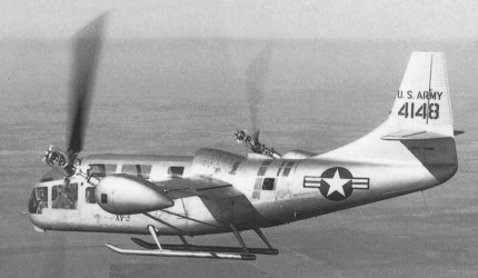
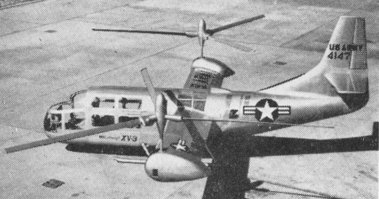
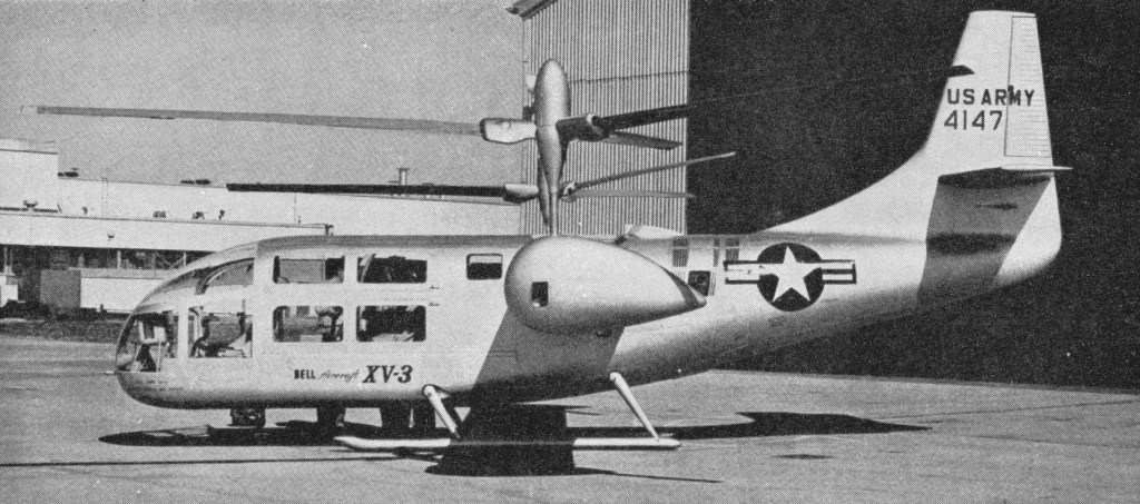
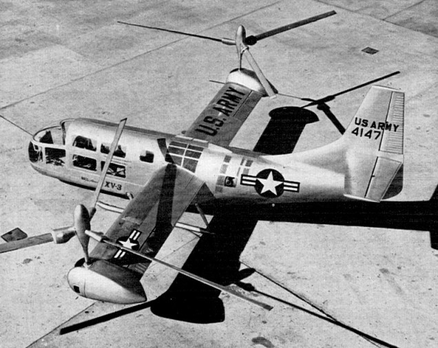
In August 1950, the Air Force and Army announced an official Tilt Rotor design competition. Bell’s proposal for their Model 200 won the competition for the XV-3 (originally designated the XH-33), and Bell was awarded a contract in May 1951. The XV-3 was built and initially flight tested at Bell’s Ft. Worth, Texas, facility. Two prototypes were built, carrying tail numbers 4147 and 4148. The basic configuration was a metal fuselage with the metal wing mounted mid fuselage. A helicopter-like rotor was mounted on each wing tip. The rotor shafts were oriented in a vertical position for take-off, landing and hover like a helicopter, and moved to the horizontal position for forward flight like a conventional aircraft. A single Pratt & Whitney R-985-AN-1 Wasp Junior piston engine, producing 400hp for flight and 450hp for take-off, was located in the fuselage just behind the wing. A series of gearboxes and drive shafts transferred power to the rotors. Fuel was stored in a 380 litres tank located in the fuselage just under the wing. The fuselage length was 9.25m, the wing span was 9.53m, the height was 4.14m, and the wing area was 10.8 sq.m. The maximum speed was predicted to be 252km/h. Three-bladed, fully articulated, 7.63m-diameter rotors were used initially. They were driven through a two speed transmission that could be shifted to a lower gear to allow the rotors to turn at a lower speed while the engine maintained a higher speed for greater cruise efficiency. The rotor tilt was controlled by an electric motor enclosed in a fairing at each wing tip. Each rotor could rotate through a 90-degree arc from vertical to horizontal in 10 to 15 seconds. The pilot could stop or reverse the rotor motion at any point. Steady, stable flight could be maintained with the rotors in any intermediate position. The XV-3 was intended as a research vehicle to evaluate the Tilt Rotor concept and to provide design and test data, but the military contracting rules at the time required that it also be designed and demonstrated with a military mission capability. The XV-3’s military mission was observation, reconnaissance, and medical evacuation. It had mounting points for two litters. Tests confirmed that good propulsive efficiencies for cruise could be obtained using helicopter rotors as propellers by reducing the rotational speed to about half of that used for hover. Only minor design changes were recommended as a result of tests. What the wind tunnel tests did not look at was the impact of the large, slow turning rotors on the aeroelastic and longitudinal stability of the aircraft at cruise speeds. Aeroelastic effects, which are the coupling of the bending motions of various flexible components on the aircraft, plagued the XV-3 throughout its early life. The first XV-3 (serial 54-147) was constructed between January 1952 and December 1954. The aircraft rolled out on February 10, 1955, and following roll out, airframe and control system proof load tests, vibration surveys, and system functional tests were performed. Then, with the XV-3 mounted on a tie down stand, full conversions and operation in helicopter and airplane modes were tested. Ground runs included a rotor stability survey and ten hours of full power operation. These ground tests were completed by August. No major difficulties were noted, and rotor stability checks showed the aircraft to be free of any resonance tendencies.
The first hover flight was made on August 11, 1955, by a Bell test pilot, but limited progress was made in flight testing during the next three years due to continuing problems with wing/pylon/rotor instabilities during flight. The first of these occurred after only one week and 1.2 hours of flight time, during an air taxi test. It resulted in a hard landing, and the XV-3 sustained rotor and airframe damage. While the damage was not extensive, the discovery of the instability raised major concerns. Repairs were made, and several modifications also were made which were felt would eliminate the elastic coupling problem. These included stiffening the rotor controls and adding external struts to make the wing more rigid. The trailing 25 percent of the wing was made to droop during hover to reduce disturbance to the rotor airflow during hover, and also to reduce stall speed to 85 knots, making transitions at a lower speed possible. 200 hours of ground runs and tie down tests were made to evaluate these modifications before clearing the XV-3 to fly again. The next hover flight finally occurred on March 24, 1956. Bell finally began envelope expansion flights in June 1956 and performed a nacelle tilt of 5 degrees on July 11. By July 25, they reached 70 degrees tilt and 150km/h forward speed when another rotor instability was encountered. Flight testing resumed on September 26 after more modifications were made to the rotor system and ground run evaluations were completed. On October 25, during another test flight, 4147 encountered another very severe inflight rotor instability and crashed. The pilot was seriously injured, but survived. Bell took a serious look at the entire rotor system, and decided that the basic design and characteristics of the three-bladed articulating rotor system were unsatisfactory for the XV-3. Prior to resuming flight testing with the second prototype, 4148, Bell made numerous changes. They kept the R-985 engine, despite its limited power, because of its very good reliability record. The flush engine cooling air inlet was replaced with a scoop that spanned across the top of the fuselage, from one wing root to the other. As had been done with 4147, the rotor controls were stiffened and the wing was braced with external struts on the bottom. The number 2 XV-3 was shipped to NASA’s Ames Research Center, where it flew in their 12m x 24m wind tunnel in September and October 1957. Serious flutter problems with the original three blade rotors were confirmed, and Bell decided to replace them with two-bladed, semi-rigid type rotors of 7.3m diameter, mounted on shorter masts. The semi-rigid, versus the fully articulated design, in itself further increased rigidity, which would decrease the possibility of aeroelastic coupling. While in the wind tunnel, pilots were able to practice conversion procedures and gear changes. Further changes to the two bladed rotor/pylon design were still required to eliminate pylon oscillations, but these changes were tested while still in the tunnel, and again appeared to eliminate the problem in all conditions that were tested. The pilots found conversion to be quite easy, but engine gearbox shifting proved to be difficult, requiring considerable manipulation of the pitch controller and throttle throughout the twenty second process. Flight testing of 4148 (serial 54-148) began at Bell on January 21, 1958. Conversions to 30 degree pylon angle and speeds up to 205km/h were accomplished by April 1, 1958. Pilots also demonstrated autorotation to a landing following a simulated engine failure. Helicopter characteristics were rated as good, especially in high speed forward flight, and vibration levels were lower than expected. By May 6, another rotor oscillation was encountered in flight at a 40 degree pylon angle, and the aircraft again was grounded. Bell, the Army, and NACA decided that another series of wind tunnel tests was in order. The 12m x 24m tunnel at Ames Research Center was heavily scheduled through the summer, and the XV-3 sat grounded until being shipped to Ames in September. During this time, Bell conducted analog computer simulations to further analyze the instability problem and recommend configuration changes prior to beginning the wind tunnel tests. During October 1958, the XV-3 finally went into the 12m x 24m foot wind tunnel at NASA Ames, and more refinements resulted. Changes included increasing the control system stiffness to three times greater than original, adding counterweights in to the rotor collective control mechanism, and increasing the blade sweep angle. Flying resumed on December 11, and on December 17, the XV-3 achieved 30 degrees tilt, and on December 18 achieved 70 degrees tilt. After making a few minor rigging corrections, a second flight was made and a full conversion to 90 degrees finally was achieved. The conversion was made in steps, starting at 167km/h in full helicopter mode and finishing at 213km/h in full airplane mode. A second full conversion was made the next day. This was three years after the date projected for full transition at the time of the XV-3’s roll out. Over the next ten weeks, final aerodynamic and control system refinements were made, including adding a large plywood ventral fin to improve the poor directional stability. With all the changes that were made to the rotors and pylons, Bell tried something new to see if the wing really was contributing to the instability. The strut attachments were modified with locking devices that allowed the XV-3 to fly with the supporting struts either locked in place to maintain wing rigidity or loose to provide no support to the wing. They were hydraulically actuated, and the pilot could switch between the two settings in flight. Bell assumed that if the instability resumed with the struts unlocked, then the wing indeed did contribute to the problem. The new device was tested on January 16, 1 959, at rotor angles up to 85 degrees from vertical with no instability problems. On the January 22, the struts were removed and the XV-3 flew up to 220km/h with the rotors 50 degrees from vertical, again with no instability noted. A wheeled landing gear was added to the landing skids, and short take-offs were made on April 13, 1959, using less than 60m of runway, and using only two thirds power. Optimum rotor tilt angle was found to be ten degrees forward of vertical. The first in-flight gear change was made on April 14, 1959, and a forward speed of 220km/h was achieved at a much lower engine speed with an accompanying lower vibration level. The gear change took about ten seconds to accomplish. The process was very similar to shifting a manual transmission in a car, requiring manipulation of the aircraft’s collective control, throttle, and clutch.
By April 24, 1959, the XV-3 was ready for formal evaluation by the military. It was shipped to Edwards AFB for a two month flight evaluation that began on May 14, 1959. The joint Air Force and Army evaluation consisted of 38 flights and a total of 29.6 hours. Forty conversions were made, as were twenty gear shifts to lower the rotor speed while in airplane mode. Also demonstrated were power-off conversions from airplane mode to helicopter mode followed by autorotation to a safe landing. Flights up to 3660m were performed. Air Force and Army evaluators concluded that conversions could be performed easily at all airspeed and fuselage attitudes that were tested. They considered the concept to be operationally practical because of low down wash velocity and temperature, low vibration, reasonable noise levels, and excellent reliability. The XV-3 demonstrated good behavior during stalls, good rolling take-off performance, and good basic controllability without electronic or mechanical stability augmentation. On the negative side, items related to the prop rotor concept included an erratic lateral darting tendency and roll oscillations during hovering in ground effect. A large increase in power was needed as hovering flight was approached. Weak longitudinal and lateral-directional stability was also observed at low speed in helicopter mode, as was excessive blade flapping during longitudinal and directional maneuvering in airplane mode. There was high parasite drag in all configurations at high speeds. And last, the XV-3 displayed a fore/aft surging motion, especially severe in rough air, attributed partly to the use of large, lightly loaded rotors as propellers. Performance was significantly less than predicted and weight had grown. The design empty weight was 1580kg and grew to 1895kg, before the Air Force added 72kg of instrumentation. At a gross weight of 2165kg, only the test pilot and about 190 litres of fuel (half the fuel tank capacity) could be carried. This gave a maximum endurance of one hour. In airplane mode in high gear and full power at 1220m of altitude, cruise speed was 189km/h true airspeed and wing stall was 185km/h. In low gear and full throttle, cruise increased to 213km/h and wing stall was reduced to 174km/h. The XV-3 was dived to 287km/h, which was the top speed due to limits of collective pitch. Short period longitudinal dynamic stability began to deteriorate at 222km/h, and was considered unacceptable at 240km/h. At the completion of Air Force testing, the XV-3 was shipped to NASA Ames where it remained on flight status through July 1962. By the time its flying career ended, the XV-3 had been flown 270 times by 11 pilots for a total of 125 hours. 110 full conversions were made by nine different pilots, six of whom performed the conversion on their first flight.
Flight testing of the XV-3 clearly demonstrated that technology had not yet developed an understanding of the aeroelastic coupling that could occur between the wing and a large, slow-turning rotor located at the wing tips. It wasn’t until the mid-1960s that engineers finally had a relatively complete understanding of the coupling problem, following the development of sophisticated analytical tools and more capable computers. Although the XV-3 demonstrated the feasibility of the Tilt Rotor concept, it was limited because of low power, an unsophisiticated flight control system, and relatively low twist, helicopter-like rotor blades. Several times Bell proposed replacing the powerplant with a Lycoming T-53 turboshaft engine of 600hp and making rotor and control modifications to eliminate the concept-related deficiencies identified during the Air Force evaluation, but the XV-3 never flew again. However, the XV-3’s career was not over yet. Under a NASA contract, Bell continued studying the phenomena of aeroelastic coupling and ways to improve high speed flight. Two additional sets of wind tunnel tests using the XV-3 were performed. The first was done in July 1962, evaluating several changes aimed at increasing maximum speed, improving high-speed flight characteristics, and decreasing the rotor flapping that occurred during maneuvering. The tunnel was run at 240km/h before instabilities set in. Following modifications, the instabilities did not return until 295km/h. Using these results, Bell felt that they finally had a good understanding of the problem. In May 1965, the XV-3 returned to Bell, where further study, modifications, and ground runs were performed between July 1965 and March 1966. It then returned to Ames and again entered the 12m x 24m tunnel for the fourth, and last, time in May 1966. This time, the XV-3 was tested to 365km/h, the limit of the wind tunnel, without encountering any of the oscillations that had plagued the aircraft throughout its career. However, on May 20, while running at maximum tunnel speed and taking the last planned data point, both rotors tore loose following a wingtip fatigue failure, damaging the aircraft and permanently ending the XV-3’s career. Following these events, the XV-3 was placed in storage for many years, spending time at Wright-Patterson AFB and Davis-Monthan AFB. Eventually the U.S. Army Aviation Museum at Fort Rucker, Alabama, acquired it for display. Small size and lack of capital of Platt-LePage Aircraft, along with lack of orders for military aircraft caused the Platt-LePage Aircraft Co. to shut down in August of 1946. The McDonnell Aircraft Co. obtained most of the helicopter patents from Platt-LePage during the liquidation of the company, along with the personnel responsible for the twin engine project. Robert Lichten an ex-Platt-LePage engineer went to Bell Helicopter and developed the Tilt-Rotor idea into the XV-3, an examination of the original patent by Haviland Platt shows a remarkable similarity between the two ideas, and Bell Aircraft eventually paid Haviland Platt for the use of his patent.
Bell XV-3 Engine: 1 x Pratt & Whitney R-985, 330kW / 450hp Type of rotors: 2 x 3-blade combined rotor-propellers Propeller diameter: 7.32m Wingspan: 9.15m / 30 ft Length: 30 ft Take-off weight: 2177kg Empty weight: 1633kg Max speed: 280km/h Ceiling: 3600m Seats: 4
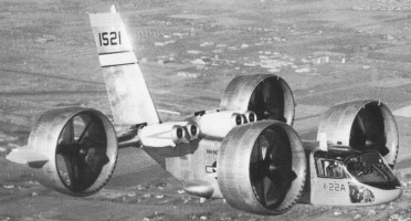
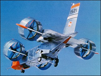
The X-22A was designed for evaluation of the tilting-duct concept in an airframe that might form the basis of a light V/STOL transport. It was also designed to provide a versatile platform capable of general research on V/STOL handling qualities using a variable stability control system. The Tri-Service V/STOL Transport Program addressed needs of the Army, Navy, and Air Force, to develop a small number of prototype V/STOL transport aircraft that used different concepts and to perform operational evaluations of their usefulness. The Navy studies showed that a duel tandem ducted fan configuration permitted a shorter wing span for a given weight, allowing a stubbier design that could fit on existing carrier elevators and would eliminate the need for complex wing folding mechanisms. The duct around each of the four props also would improve propeller efficiency and provide a safety benefit to personnel working on a ship’s flight deck. The Navy awarded a $27.5 million contract for the design and development of two identical X-22s to Bell Helicopter of Niagara Falls, NY, in November 1962. Bell’s internal designation was the Model D2127. Bell had already Bell built and flew the Air Test Vehicle and X-14 VTOL research aircraft. Representative of a possible small V/STOL transport, the X-22 could carry a 540kg payload and could carry up to six passengers. Its length and wingspan were each a little over 11.9m, and maximum gross weight was 7530kg.
The rectangular fuselage accommodated at its rear a wide-chord wing fitted on its leading edges with two groups of two 1250-shp (932-kW) General Electric YT58-GE-8B/D turboshafts to drive four propellers (or fans) located inside annular ducts. These last were located at the tips of the wings and the short span foreplane and could be turned between the vertical (for vertical take-off and landing) and the horizontal (for forward flight). Change in the propeller pitch produced the thrust modulation for control, and was supplemented by movement of aileron in the slipstream of each duct. The “B” and “D” designations on the engines referred to two engine configurations that differed only by their fuel controllers. They powered a common drive shaft that turned all four props. These engines had both controllers and switched between them automatically based on whether the X-22 was operating in hover mode or cruise mode. 465 gallons of useable fuel was carried in fuselage tanks. The power transmission system consisted of a total of ten gearboxes. It reduced the engine’s nominal 19,500 revolutions per minute speed down to the propellers’ nominal 2,600 revolutions per minute. This arrangement also allowed all four props to continue operating with any number of engines failed or intentionally shut down. The four Hamilton Standard propellers, 2.1m diameter, 3-bladed props were fabricated of fiberglass bonded to a steel core, making them 25 percent lighter than metal props yet giving them three times the fatigue strength. A nickel sheath was mounted over the leading edge. Very high prop efficiency was achieved by placing the props inside of the ducts, so much so that the X-22 could still take off on three engines, fly on two, and make a conventional landing with only one. The two forward ducts were mounted to small pylons on the forward fuselage, and the two rear ducts were mounted to stubby, dihedralless wings on the aft fuselage. Hydraulic actuators rotated each of the four ducts, but mechanical and electrical interconnections insured that all rotated together. Thrust control could be obtained by varying the blade angle. Four elevens, one placed at the rear of each ducted fan assembly, were the only control surfaces. Placing the elevons in the prop slipstream made them very effective, even at low airspeeds. Despite the significant looking vertical stabilizer, there was no rudder. Movement of the elevons and changes to the prop pitch achieved all flight control. Flight control in horizontal flight was achieved using a conventional looking control stick for pitch and roll. Moving the stick caused the elevons to move, either differentially between the front and rear for pitch, or differentially on left and right sides for roll. Yaw was achieved by moving the rudder pedals, which changed the propeller blade angles to produce differential thrust. There were also throttles for each engine and a lever to control the angle of the ducts. In forward flight, the front ducts were rotated to 3 degrees up from horizontal and the rear ducts rotated to 2 degrees below horizontal. This gave an optimum incidence of 5 degrees between the two pairs. The cockpit arrangement included two zero-zero ejection seats set side-by-side, full conventional instrument displays (plus a master tachometer for propeller revolutions and a duct angle indicator) duplicated for each pilot. Engine controls were gathered on the central console. While hovering, the pilot used the same control stick to control pitch and bank motions. Stick inputs caused the flight control computer to command minute changes to the prop blade angles to vary the thrust, causing the X-22 to tip forward, aft, or sideways. Yaw was controlled by moving the rudder pedals, by differential movements of the elevons between the left and right sides. The pilot also could rotate the ducts to assist the fore/aft motion during hover. During transition, with the ducts at some intermediate angle, the pilot’s control inputs produced mixed propeller pitch and elevon deflections. The ratio of mixing between the props and elevons was a function of the duct angle. The ducts rotated at 5 degrees per second. The X-22’s flight controls also included a variable stability system. This was another flight control computer that modified the basic airplane responses so that the characteristics of other aircraft, either real or imagined, could be produced. The variable stability system followed algorithms that were developed specially for each test and programmed into the computer. They produced extra control surface motions that caused the X-22’s flight characteristics to be varied, thus producing motions that are not characteristic to the X-22 airframe, but rather to the aircraft being simulated. This gave the X-22 the capability to perform research that would be applicable to a broad range of other aircraft, not just the unique characteristics of the X-22 itself. The Cornell Aeronautical Laboratory designed the variable stability system. The first X-22, US Navy Bureau Number 151520, rolled out on May 25, 1965, and was followed by fifty hours of propulsion tests in a test stand. The flight test program was undertaken by Calspan Corporation, in Buffalo, New York, under the auspices of the U.S. Navy. The first flight in hovering mode was not made until March 17, 1966. On this 10-minute flight, four vertical take-offs and landings and a 180 degree turn were made. It then performed a series of STOL take-off and landing tests with the ducts tilted at 30 degrees. The first X-22 was damaged beyond repair on its fifteenth flight on August 8, 1966. It had flown only 3.2 hours, but suffered a dual hydraulic failure about four miles from its base at Niagara Falls Airport. The first transition from wing-borne flight to vertical flight was made under the stress of an emergency landing. The fuselage broke in half, with the rear section coming to rest inverted. While the aircraft was lost, neither pilot was injured. Swivel fittings were used in the ducts to provide hydraulic fluid to the elevon actuators. Both failed due to excess vibration. The fix included replacing the swivel fittings with loops of flexible tubing, replacing the aluminum hydraulic lines with ones made of stainless steel, and placing additional clamps on the hydraulic lines to minimize vibration. The first was damaged beyond economical repair and it was cannibalized to keep the second aircraft flying, although the fuselage was retained for use as a ground simulator at Calspan. The second X-22, BuNo 151521, rolled out took place on 30 October, 1965 and flew on 26 January, 1967, with Stanley Kakol and Richard Carlin in the cockpit, for a first 10-minute hover flight. Bell test pilots Stanley Kakol and Paul Miller were at the controls. The first transition being successfully made on 3 March. With pilots from Bell, the Army, Navy, and Air Force, the X-22 flew frequently over the next several years. At the completion of the Tri-Service testing in January of 1971, the X-22s completed 228 flights, 125 flight hours, performed over 400 vertical take-offs and landings, over 200 short take-offs and landings, and made over 250 transitions. It also hovered at 2440m of altitude and achieved forward speeds of 507km/h. These flights demonstrated that the X-22 had good basic stability and that vertical take-offs and landings could be performed easily. Operation in ground effect was a little less stable, but still positive. Hovering was easier than in most helicopters. In horizontal flight, all responses to pilot control inputs were excellent. Transitions were accomplished with minimum pilot workload. Landing position could be controlled precisely. The aircraft was still controllable without augmentation, but required a significant increase in pilot workload. This system provided rate damping in pitch, roll, and yaw only during hover and low speed flight. With the Navy satisfied with the basic operation, they awarded a contract to Cornell in July 1970 to operate and perform flight research using the X-22, with particular emphasis on operating in the variable stability mode.
Over the next ten years, Calspan flew five test programs:
August 1971 – February 1972: evaluation of steep STOL approach paths of 6-10 degree glide slopes, at airspeeds of 120-150km/h, with a variety of oscillatory characteristics in the pitch mode. June 1972-February 1973: continuation of previous effort, but with variation of roll and yaw oscillatory characteristics.
October 1973 – April 1975: evaluation of control, display, and guidance requirements for STOL instrument approaches. Determined desirable control system requirements and information displays for pilot use to permit transition from forward flight to a decelerating steep approach and then to a hover at 30m, followed by a touchdown, all under instrument conditions.
February 1977 – March 1978: expanded the previous experiment by evaluating the usefulness of a head-up display for STOL instrument approaches. Used precision radar distance measuring equipment to establish the aircraft’s position within 7.62mm. Evaluated a variety of display formats that presented data to the pilot, such as attitude, airspeed, altitude, horizontal location, and range to touchdown. Also, simulated the AV-8B, a specific aircraft, rather than a generic set of aircraft characteristics.
November 1978 – May 1980: generated flying quality and flight control design requirement data for V/STOL aircraft performing shipboard landings. In performing this task, typical shipboard pitching and rocking motions had to be added to the guidance beam, then various compensation schemes were programmed into the flight computer on the X-22. Hover, and then simulated touchdowns at 30m were performed.
Numerous problems were discovered and fixed during testing. While all were fixed, they were not necessarily fixed in an optimum manner, as would be done for a production aircraft. Further development may have provided an optimal solution. But, being a research aircraft, a fix that worked for the intended mission was good enough. Some of them included the following:
Failure of the linkage synchronizing the front and rear duct angles, resulting in the front ducts rotating to 30 degrees while the rear ducts remained vertical. Fortunately, this happened on the ground. The aluminum shaft that transmitted the proper duct angle was replaced with one made of stainless steel.
In forward flight with the ducts near the stall angle of attack, the airflow from the lower lip separated from the duct surface as it entered the duct, causing a very loud buzzing as the turbulent flow hit the prop. Installing a number of vortex generators on the bottom inner-lip of each duct reduced this problem significantly.
A number of fatigue cracks developed on the inside of the duct skin and ribs. Apparently this was caused by a wake of very low pressure being pulled behind each prop blade. Thus, for each revolution of the prop, the surface was hit with three pulsations of high, then low pressure. This was corrected by replacing the ribs with slimmer ones, then building up an eighteen-inch wide ring of fiberglass inside each duct, maintaining the 0.95cm clearance between the prop tip and the wall. The program office within the Navy that oversaw the X-22’s testing was disbanded. Calspan sought added research programs, but the most they could accomplish was to get the Naval Test Pilot School to use the aircraft for some V/STOL demonstration flights for their students during 1981 and 1982. The aircraft made its last flight in October 1984. Ownership was transferred to the Naval Aviation Museum at Pensacola, Florida, but the museum never had any desire to display unique aircraft that were not typical of Naval aviation use. The X-22 remained in storage at Calspan’s facility at Buffalo Airport in hopes that further projects would return this unique test vehicle to service, or at least be acquired by an aviation museum. No further work ever arose, and many efforts to transfer the X-22 to an appropriate museum in the western New York area fell through. In 1995, Calspan moved it outdoors because they needed the hangar space. To protect it from the elements, the Buffalo & Erie County Historical Society paid to cover the X-22 in a plastic wrapping. In 1998, the newly formed Niagara Aerospace Museum at Niagara Falls, NY, acquired the X-22 and placed it on display.
For two full years, the X-22A was involved in a flight-test programme with Bell and the NASA. During this period some 220 flights and 110 flying hours were logged. This phase was followed, in January 1968, by a first military preliminary evaluation during which the X-22A was examined by pilots and engineers of the three Services and accomplished fourteen flights. A second military evaluation took place at the beginning of the following April. During this period, the X-22A demonstrated. good performance such as a sustained hover at an altitude of 2400m. On 19 May, 1968, the X-22A was officially taken on charge by the US Navy which turned it over almost immediately to Calspan Corp responsible for the test programme on behalf of the Navy. The prototype had been equipped with an automatic flight control system known as LORAS (Linear Omnidirectional Resolving Airspeed System). This programme, which was broken down into several tasks, totalled 273 flights, 279.9 flying hours, 130 VTOL take-offs and 236 VTOL landings. The aircraft was flown until the autumn of 1984 when flight testing was considered terminated. The X-22A made its last flight in 1988.
Engines: 4 x General Electric YT58-GE-8B/D turboshaft, 932kW / 1250hp Wingspan: 11.96m / 39 ft 3 in Length: 12.06m / 39 ft 7 in Height: 6.3m Take-off weight: 8172kg Empty weight: 4302kg Max speed: 370 km/h Cruising speed: 343km/h Range: 716km Ceiling: 15,000 ft. Fastest Flight: 255 mph Total Flights: 500+ Highest Flight: 27,800 feet (approx)
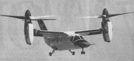
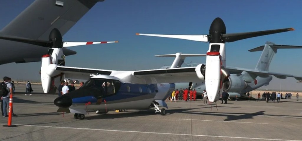
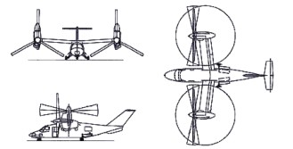
Bell and Boeing revealed in February 1996 that studies were in progress for a nine-passenger civil tiltrotor aircraft in the 6,350kg weight class, with the preliminary designation D-600. On 18 November 1996, the two companies announced that a joint venture was being established to design, develop, certify and market a six- to nine-passenger civil tiltrotor as the Bell Boeing 609. The machine has engines which pivot 90 degrees so it can take off vertically like a helicopter, then fly horizontally like a plane. Boeing withdrew as a partner on 1 March 1998 and Bell formally announced at the Farnborough Air Show in September 1998 that they had teamed with Agusta. Agusta was investing and participating in BA609 development and was to be responsible for assembly of BA609s sold in Europe and elsewhere. Preliminary design review completed May 1997. Manufacture of parts for the prototypes began in Philadelphia, August 1997, and a full-size mockup was exhibited at the Paris Air Show in June 1997. With a T-tail configuration and composite cross-shafts to keep both prop rotors turning in event of engine failure. Manual screwjack facility exists whereby the prop-rotors can be tilted into helicopter mode if the cross-shafts fail. Designed using three-dimensional CATIA digital computer design system, the airframe has design life of 20,000 flight hours. The aluminium fuselage structure has composites skinning and composites wings. The undercarriage is a retractable tricycle type, with twin nosewheels and single wheel on each-main unit. Control is by a BAB Systems triplex digital fly-by-wire flight control system, with Dowty Aerospace actuators. The T tail has conventional elevators and no rudder. Two-segment trailing-edge flaperons are fitted. Two 1,447kW Pratt & Whitney Canada PT6C-G7A turboshaft enginesc are installed in tilting nacelles at the wingtips, each driving a three-blade proprotor. Nacelle transition is achieved in 20 seconds. Fuel is in integral wing tanks with a usable capacity of 1,401 litres, and provision for auxiliary fuel tanks. The airframe carries a crew of two, side by side on flight deck, with dual controls, and a maximum of nine passengers in the standard aircraft. A crew and passenger door is on the starboard side, forward of wing. The cockpit is pressurised and air conditioned; pressurisation differential 0.38 bar. Ground-running trials began on 6 December 2002 and the first flight of the prototype (N609TR) took place (in the vertical mode only) on 7 March 2003 in Arlington, Texas, rescheduled from late 2002. The Bell/Augusta Aerospace Co said its BA 609 tilt-rotor aircraft flew at an altitude of about 15m in its first test flight. Four prototypes were produced for a 36-month flight test programme leading to certification in January 2007 under FAR Pt 25 (fixed-wing aircraft) and Pt 29 (helicopters), plus Pt 21.17(b) Special Conditions for unique components. The first prototype were used primarily for expansion of flight envelope, while the second, third and fourth airframes were dedicated to systems certification, avionics and icing approval, and FAA function and reliability, respectively.
Leonardo AW609
The order book opened on the 2nd of February 1997 at Heli Expo, with the first order placed soon after by an unspecified customer. A total of 70 were ordered by 40 customers in 18 countries by March 2003. A briefing was given to the US Coast Guard, late 1997, followed by a demonstration by the XV-15 tiltrotor concept demonstrator aboard the Coast Guard cutter Mohawk off Key West, Florida, in May 1999. In 1998 Bell Helicopter Textron acquired Boeing’s 49% interest in the Bell-Boeing 609 civil tiltrotor and has assumed full ownership.
Bell 609 Engine: 2 x Pratt & Whitney PT6C-67A, 1360kW / 1850hp Empty weight: 6300kg Max speed: 510km/h Range: 1390km Crew: 2 Passengers: 6-9
Bell Aerosystems Rocket Belts. These strap on devices had a pair of vectorable nozzles controlled by handlebars and enabled the wearer to be thrust over 15 m (50 ft). The only practical application of the Rocket Belt has been as a gimmick in a James Bond movie. Developed versions of the device have been used by NASA astronauts for spacewalking. Neat and potentially useful, the rocket belt has proved difficult to control with the finesse necessary for everyday use by non experts.