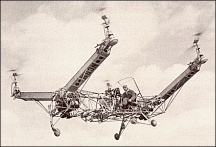
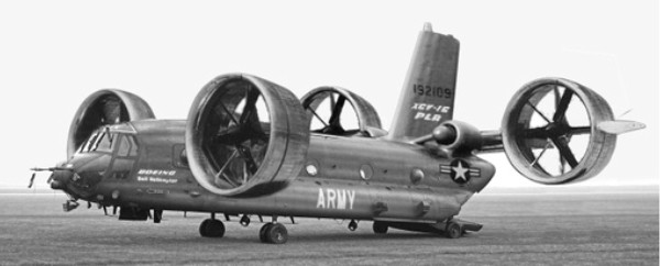
As the result of Convertawings’ further developmental work on this four rotor configuration, a first prototype was completed in 1955 and it has flown successfully.
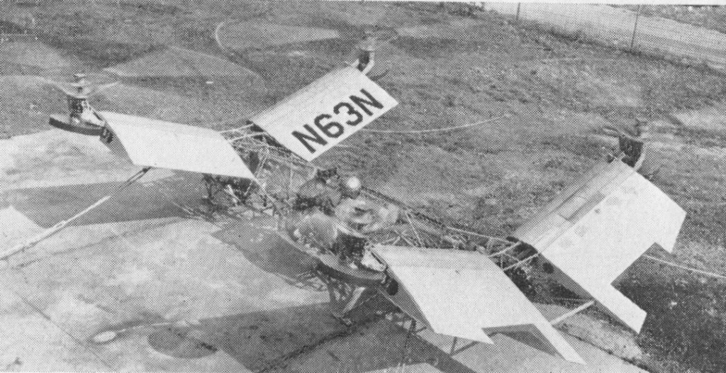
The four rotors of this helicopter are mounted laterally on outriggers in two tandem pairs. The four rotors were positioned in an “H” configuration, and the design incorporated simplified hubs with strap-mounted blades, a form of “hinge-less” rotor. The control mechanism is extremely simplified and obtained by differential change of thrust between the rotors. There is no cyclic control, but only collective control. In the experimental prototype the fuselage was of tubular steel, the booms supporting the rotors in aluminium alloy. Power is provided by two engines connected to the rotor drive system by multiple vee belts. Shafting and transmission cases ensure inter-connection between the four rotors, so that either engine can drive all of them. There is a tricycle undercarriage with two wheels in the rear section and a nose wheel which can swivel.
The first flights took place in March 1956, flown by its designer and test pilot, D.H.Kaplan. Despite successful testing and development, military support for the Quadrotor ceased after cutbacks in defense spending.
The Quadarotor A was a small test vehicle for the Projecled 60-76 passenger Model E Quadrotor on the same general lines. The Model E is intended to have four R-1820 piston-engines or Dart turboprops, mounted directly under the rotors.
However, the design – particularly its control system – was a precursor of future experimental vertical-rising aircraft.
Model A Engines: 2 x Continental 0-90, 90hp Rotor diameter: 5.92m / 15 ft Gross weight: 998kg / 1,950 lb Number of seats: 1
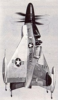
From 1949 the US Navy actively pursued a policy of VTOL research. The results were two prototypes, the Lockheed XFV-1 and the Convair XFY-1 Pogo. Both aircraft were of the ‘tail-sitter’ concept and powered by the 5500-shp (4101-kW) Allison T40-A-6 turboprop driving large contra-rotating propeller units. These provided more thrust than the weight of the aircraft, making possible VTOL operation.
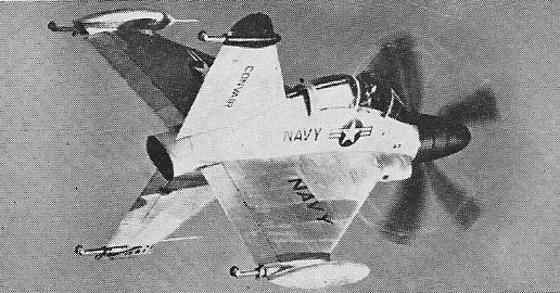
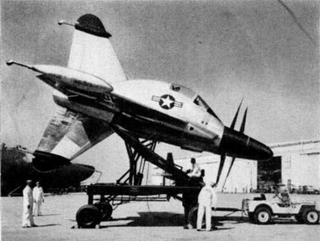
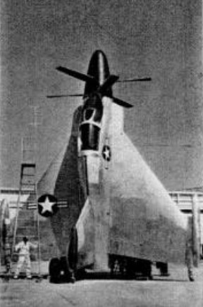
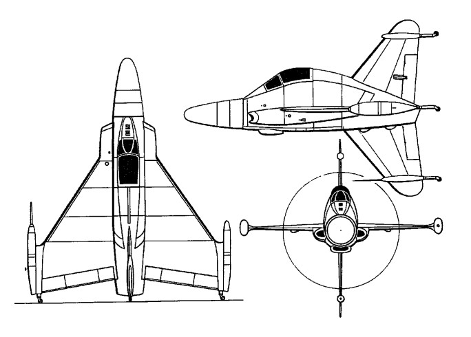
The XFY-1 was a swept delta design with large dorsal and ventral fins, all four surfaces of this cruciform arrangement carrying castoring wheels to support the aeroplane vertically on the ground. This arrangement of flying surfaces made it impossible to fit the XFY-1 with the same type of conventional landing gear as the XFV-1, so Convair received the only example of the T40 turboprop cleared for VTOL operation.
The pilot is seated in a gimbal-mounted seat which tilts forward 45 degrees when the aircraft is in the vertical position, returning to normal when horizontal flight is attained.
The Pogo made its first free VTOL flight on 1 August 1954 and in October made its first transition from free vertical to horizontal flight and back. The flight test programme was very successful in overall terms, but like that of the XFV-1 confirmed that exceptional piloting was necessary for such a tail-sitter type.
The aircraft had little castoring wheels on their fins on which they stood, towering nearly 12.2 m (40 ft) above the ground, and wingtip weapon pods.
The Pogo was equipped with a custom fitted clamshell ‘hangar’ which locked around tile aircraft and made it independent of airfield facilities so that it could be stationed anywhere.
Extensive tethered tests from a special rig were followed by a first vertical take-off and landing on 1 August 1954. Testing continued with a series of similar vertical flights before the first complete transition from vertical to horizontal flight and vice versa was accomplished on 2 November 1954. Although some 40 flight hours were accumulated by two prototypes of this experimental fighter, its development was abandoned. The aircraft did not get beyond preliminary testing.
Engine: 1 x Allison YT40-A-6 turboprop, 4362kW / 5500 shp Wingspan: 8.43 m / 27 ft 8 in Length: 10.66 m / 34 ft 12 in Height horizontal: 30 ft 9in Wing area: 32.98 sq.m / 354.99 sq ft Max take-off weight: 7371 kg / 16250 lb Empty weight: 5345 kg / 11784 lb Loaded weight: 10,000-11,000 lb Max. speed: 982 km/h / 610 mph Ceiling: 13320 m / 43700 ft Armament: 4 x 20mm cannon (proposed) or 46 x 70mm rockets
In 1959, the U.S. Army, through its Trans¬portation Research and Engineering Command, initiated the development of three types of VTOL research aircraft in a programme aimed at pro¬ducing a flying jeep. Fundamentally a cross between an Army jeep and a reconnaissance helicopter, this type was intended ultimately to operate at speeds of about 50 mph a few feet above the ground, carrying a payload of about 1000 lb. Contracts were placed with the Chrysler Corporation, Acrophysics Development Corp¬oration and Piasecki Aircraft Corp¬oration. The Chrysler VZ 6, like the Piasecki flying jeep, was of the ducted fan type, using two fans in tandem with the pilot and engine in between. Work on this configuration had been going on at the Chrysler Defense Engineering Company since 1955 and a unique feature of the design was the use of rigid fixed pitch three blade rotors or fans. Since the fans could not therefore contribute to control of the aircraft, Chrysler developed a system of control vanes. Pitch control came from lateral vanes across the duct intakes and yaw and roll control came from longitudinal vanes in the duct exit. The engine was located in the center of the rectangular-shaped vehicle, next to the off-set pilot’s position. Rubber skirts around the outside of the vehicle’s bottom edge helped sustain the fan-generated lift. A 373 kW (500 hp) Lycoming engine powered the VZ 6, which weighed about 2,300 lb. fully loaded and was 23 ft. long. The diameter of the ducted fans was 8 ft. 6 in. During 1959, the VZ 6 (58 5506) made some tethered hovering flights. On the first attempt at a free flight it got out of control and overturned. The prototype was not repaired and the second example (serial 58-5507) which had been ordered (58 5507) was not completed. Both prototypes were disposed of in 1960.
Chrysler VZ-6 Engine: 1 x Lycoming piston, 370kW Rotor diameter: 2.6m Length: 6.55m Height: 1.58m Take-off weight: 1080kg
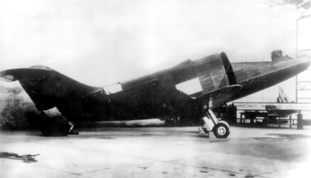
The Heliconair HC-Ib Convertiplano sits nearly finished in a hangar. The slit behind the cockpit was the intake for air used to cool the fuselage-mounted R-3350 engine. The scoop on the upper fuselage brought air to the engine’s carburetor. Note the Spitfire wings and main gear.
Immediately following World War II, Germany was prohibited from designing and manufacturing aircraft. Post war, Henrich Focke assisted with helicopter development in France and worked for a car company in Germany. He also spent some time in the Netherlands, where he began to design a VTOL aircraft that was capable of relatively high speeds. In 1952, Focke was recruited by the CTA (Centro Técnico de Aeronáutica or Technical Center of Aeronautics) to work in the recently established ITA (Instituto Técnico de Aeronáutica or Technical Institute of Aeronautics). The ITA was the first of four institutes formed by the CTA, all of which were located in São José dos Campos, Brazil. Brazil was working on building an aeronautics and aerospace industry and was actively recruiting German engineers. In addition to Focke, many of his associates and former co-workers were also recruited.
The CTA was impressed with Focke’s VTOL aircraft design and approved its construction. The CTA believed that the aircraft’s capabilities would allow it to reach remote parts of Brazil. Focke set to work on the aircraft—a tiltrotor convertiplane design that was partially inspired by the Fa 269. The aircraft was known as the Heliconair HC-I Convertiplano. Its fuselage and wings were fairly conventional for an aircraft, but it had of two sets of rotors. One pair of rotors was placed near the nose of the aircraft, and the other pair was placed between the wings and tail. All of the rotors were of a tractor configuration and rotated up for vertical flight. The HC-I accommodated two pilots in the cockpit and four passengers in the fuselage. The aircraft’s estimated performance included a top speed of 311 mph (500 km/h) and a range of 943 miles (1,517 km).
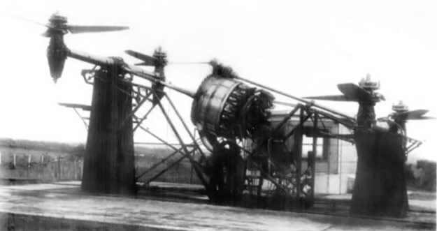
The test rig for the engine, transmission, gearboxes, shafts, right-angle drives, and rotors illustrates the complexity of the HC-Ib’s power system. The R-3350 engine did not have any Power Recovery Turbines, which means it was not a Turbo Compound engine.
To save time and money, the decision was made to build the HC-I using the wings and the horizontal stabilizer from a Supermarine Spitfire. A Spitfire XIVe (RM874) was purchased without its Rolls-Royce Griffon 65 engine from Britain by the Brazilian Air Attaché on 19 December 1952. A new fuselage was built to house a 3,000 hp (2,237 kW) Armstrong Siddeley Double Mamba turboprop engine behind the passenger compartment. However, Armstrong Siddeley and the British did not want one of their new, advanced engines being used in such a radical project and declined selling a Double Mamba engine to Brazil.
Focke and the Convertiplano team changed the HC-I’s design to accommodate a 2,200 hp (1,641 kW) Wright R-3350 radial engine and redesignated the aircraft HC-Ib. The R-3350 was larger and heavier than the Double Mamba, and it produced less power. Some sources state a Turbo Compound R-3350-DA3 (3,250 hp / 2,424 kW) was used, but images show that there are no Power Recovery Turbines on the engine installed in a test rig. Extensive modifications to the aircraft’s fuselage were required to accommodate the air-cooled engine. The passenger compartment was omitted, and the R-3350 was installed in the middle of the fuselage. An annular slit behind the cockpit was added to bring in cooling air for the engine. After passing through the engine’s cylinders, the air exited via a jet-like duct at the rear of the aircraft. The Spitfire’s landing gear was strengthened to compensate for the R-3350’s weight.
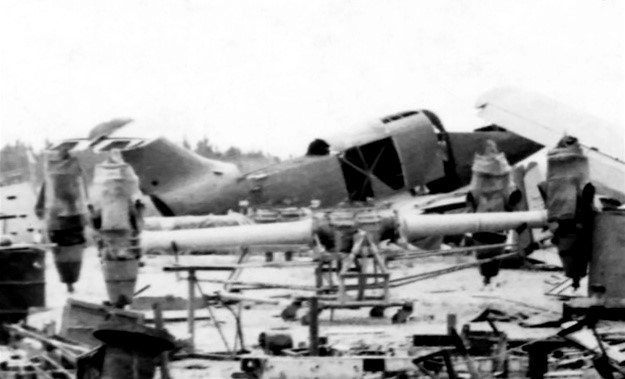
The HC-Ib sits in the background with the front and rear gearboxes and rotor drives in the foreground. The rotor blades, the only surviving component of the Convertiplano project, are not seen in the image. Note the opening at the rear of the fuselage, which was the exit for engine cooling air.
A gearbox transmission mounted to the front of the R-3350 split the engine’s power to two shafts. The front shaft extended from the engine to the front gearbox. The front gearbox had shafts that extended to the left and right. These shafts led to right-angle gearboxes that powered the front rotors. Power delivery for the rear rotors was more complex. A shaft extended vertically from the transmission on the front of the engine and met a right-angle gearbox positioned directly above the engine. From the right-angle gearbox, a shaft extended back to the rear gearbox. The rear gearbox had the same shafts and right-angle drives for the rear rotors as the front gearbox. The transmission and gearboxes were designed by Willi Bussmann and built by BMW in Germany. Bussmann was a former BMW employee and had worked with Focke on several Focke-Achgelis projects.
Each rotor consisted of three blades. The blades were built in Sweden and made of a steel frame that was covered with wood. The blades’ pitch automatically adjusted and had collective and cyclic control. The rotors were counter-rotating, with the right rotors turning counterclockwise and the left rotors turning clockwise. The HC-Ib had a 37 ft 6 in (11.42 m) wingspan and was 35 ft 3 in (10.74 m) long.
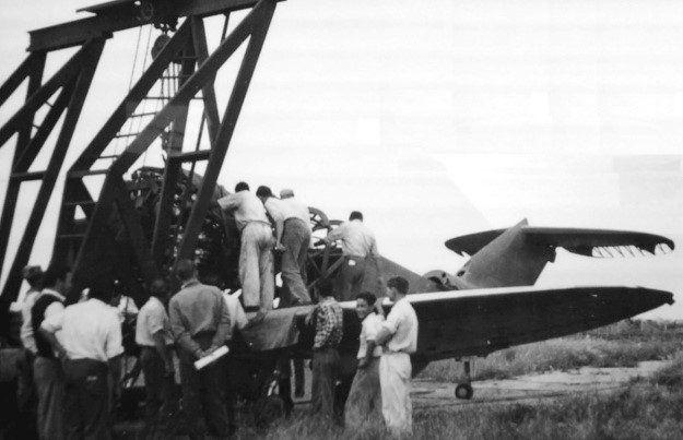
Given the state of the aircraft and the surrounding unchecked growth of vegetation, it can be assumed this image is of the R-3350 engine being removed sometime after the HC-Ib project was cancelled. The image does give proof that the engine was installed in the airframe at one point.
A rig was built, and tests of the engine, gearboxes, shafts, right-angle drives, and rotors began in late 1953. However, vibrations from the radial engine caused some issues that took time to resolve. The HC-Ib airframe was almost completely constructed and had its engine installed when the project was cancelled in 1955. The aircraft was more expensive than anticipated, and interest in the HC-1b had steadily declined after the switch to the R-3350 engine. To make matters worse, many of the Germans returned to Europe or went to the United States as their contracts with the CTA expired. Some Germans did stay and ultimately became part of Embraer. After the project was cancelled, the HC-Ib Convertiplano was left to rot in outside storage for some time and was eventually scrapped in the 1970s. There are some reports that the rotor blades are the only part of the aircraft that survived.
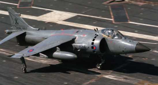
The Harrier family line consists of four major versions composed of the Hawker Siddeley Harrier, the British Aerospace (BAe) Sea Harrier, the Boeing/BAe AV-8B Harrier II and the BAe Systems/Boeing Harrier II. The initial production model and beginning of the Harrier lineage was the Hawker Siddeley Harrier. The Sea Harrier became the dedicated navalized version of the base Harrier and utilized for air-defense as a primary role and ground strike as secondary. The Sea Harrier also made use of the powerful Blue Fox radar and was a direct development of the land-based RAF Harrier GR.3. The Boeing/BAe AV-8B Harrier II became a “second generation” Harrier and is a highly-modified version of the original Harrier for use by the USMC while the BAe Harrier II is a British-modified strike version of the USMC Harrier II.
Evolved from the Hawker P.1127 vertical take-off technology demonstrator, whose intended supersonic development (the P.1154), was cancelled, the BAe Harrier is powered by a vectored-thrust engine. The first of six prototypes was flown in August 1966, and Harriers began to enter RAF service in 1969. The RAF’s first squadron was formed with Harrier GR.Mk.1 aircraft, the designation subsequently changing to Harrier GR.Mk.1A and then Harrier GR.Mk.3 as the Pegasus progressed from the 8709-kg (19,200-1b) Mk 101 through Mk 102 to the Mk 103. The two-seat trainer, with longer fuselage and taller fin, was similarly designated Harrier T.Mk 2, Harrier T.Mk.2A and Harrier T.Mk.4. Fourteen two-seat T Mk 10s, based on the USMC’s TAV-8B, are on order for the RAF. Powerplant is one 21,750 lb st (9675 kN) R-R Pegasus 11 turbofan. Despite power increases, the Harrier is unable to take off vertically with a full weapon load, but can take off from a short length of road or semi-prepared strip in the STOVL, (short take-off. vertical landing) mode for tactical concealment. Equipped from the outset with a Ferranti FE541 inertial navigation system with head-up display, the RAF aircraft were fitted from 1976 with a Marconi LRMTS (laser ranger and marked-target seeker) resulting in a much extended profile to the nose. A Marconi ARI 18223 E-J band radar warning receiver was added to the fin and extreme rear fuselage at the same time. The Harrier carries a single oblique camera in the port side of the nose, but may be equipped with a sensor pod beneath the fuselage for more extensive reconnaissance, Following the production of six pre-production aircraft, the RAF received 114 single-seat Harriers and has ordered four more for replacement of Falklands losses. US Marine Corps contracts covered 102 AV-8A aircraft (now converted to AV8C standard), and the Spanish navy acquired 11 VA.1 Matador aircraft. Two-seat trainer orders cover 23 for the RAF, T.Mk.4 (those not fitted with LRMTS being Harrier T.Mk.4A aircraft), fitted with laser nose and tall fin, eight TAV-8A aircraft with pointed nose, as TAV-8S by Spain, two VAE.1 Matador aircraft, a Harrier T. Mk.4 and three navalized Harrier T.Mk.4M aircraft for the Royal Navy, plus 4 company demonstrator. Developed as the GR.5 for the RAF and the AV-8B Harrier II for the USMC, the GR.5 features six underwing pylons, larger canopy, and outrigger wheels further inboard than the GR.3. A total of 300 (plus 28 two seat TAV-8B trainers) for the USM and 60 GR.5s for the RAF. Spain ordered 12 EAV-8Bs from 1987. The improved GR Mk 7 is for RAF night attack use, with Smiths HUD and GEC FLIR.
After the first successful landing of a P.1127 XP831 trial Harrier on the deck of the HMS Ark Royal on February 8, 1967, the legacy of the Sea Harrier began. The suitability of Harriers for operation from ships at sea led to a decision, in 1975, to develop a special version of this aircraft to equip the Royal Navy’s new ‘Invincible’ class of anti submarine cruisers and the anti submarine carrier HMS Hermes.
Taking the GR.Mk 3 as the starting point, a new redesigned forward fuselage (with folding nose cone) was built to house a Ferranti Blue Fox radar. The cockpit was revised as more ergonomically friendly while the pilot’s seating position was raised ten inches to afford for better visibility out of the cockpit under a new “bubble” type canopy. The Martin-Baker Mk 9 series ejection seat was replaced by the newer and faster-reacting Mk 10 model. The HUD (Heads-Up Display) was now be powered by a more powerful computer than that as found on the land-based Harrier. A Doppler pulse radar was fitted in place of the inertial-based unit of the GR.Mk 3 to compensate for air travel over the ocean. The Sea Harrier saw its radio system updated as well as the implementation of a simplistic autopilot. Vertical hovering controls were improved while the original landing gear undercarriage arrangement was retained. Though the Pegasus Mk 104 series turbofan engine received its new designation, it was nothing more than a “navalized” version of the land-based 21,500lb thrust Mk 103 series. All of the five underwing and centerline hardpoint pylons were revised for better efficiency and reaction while the outboard stations were now wired for compatibility with the AIM-9 Sidewinder short-range air-to-air missile. Much of the magnesium of the original Harrier construction was replayed by aluminum alloys to help retard corrosion of the metal at sea. Likewise, the folding nose cone helped keep the Sea Harrier’s footprint aboard the carriers as small as possible. The trainer T.Mk 4N did not feature the space-saving hinged folding nose cone and therefore could not be stored under the flight deck. Despite all of these internal changes, the Sea Harrier weight only 100lbs heavier than her land counterpart. The first Sea Harrier (Hawker Siddeley designation of P.1184) achieved flight on August 20th, 1978 at Dunsford and later this same aircraft became the first Sea Harrier to land on the HMS Hermes on November 13th. No. 700A Flight squadron was formed to handle the intensive deck trials for the new aircraft and clear it for operational use. To expedite development even further, a pair of specially-modified Hawker Hunter T.Mk 8 trainer airframes were fitted with Sea Harrier equipment for critical in-flight testing of systems in action.
The first of 34 Sea Harriers for the Royal Navy entered service in June 1979. Three pre-production aircraft were on order followed by an order for 31 production units and a single two-seat T.Mk 4A trainer.
By the end of the first round, some 57 single-seat production Sea Harriers were ordered thanks to follow-up contracts and high expectations. The second production Sea Harrier (XZ451) completed her first flight on May 25th, 1979 and then came to the Royal Navy Intensive Flying Trials Unit (IFTU) at Yeovilton on June 18th of that same year. The squadron was then disbanded on March 31st, 1980 and reformed as No. 899 Squadron. The initial carrier-deployed Sea Harrier unit became No. 800 aboard HMS Invincible. Overall the Sea Harrier looked every bit the part of her land-based sisters complete with her swept-back high-mounted monoplane wings, conventional single-finned tail unit and unique two-legged undercarriage complimented by two wingtip wheeled struts. The engine series remained the Rolls-Royce brand Pegasus type of which itself was a special navalized version of the Mk 103 – now marked as the Mk 104 – with an impressive rating of 21,500lb standard thrust output (Sea Harriers, like the base Harrier, were subsonic aircraft incapable of breaking Mach 1 or utilizing afterburner). The powerplant powered the four all-important thrust vectoring nozzles affixed as pairs to the either side of the fuselage body. Since the Sea Harrier was branched off of the land-based Harrier GR.3 production models (and was only acquired in limited quantity), it maintains only a handful of variants to its name. The initial production version became the FRS1 and entered service in April of 1969. The FRS1 had a maximum speed of 1,185km per hour and a cruising speed equal to 850km per hour at 36,000 feet. High altitude combat radius was limited to 750km. Maximum take-off weight was 26,200lbs. The Sea Harrier made use of a pair of optional 30mm ADEN cannons mounted to the sides of the fuselage centerline with approximately 100 rounds per cannon. This could easily be complimented with an array of air-to-air and air-to-surface weaponry to fit the mission role up to 5,000lbs to include anti-ship missiles. Munitions were fielded on four underwing hardpoints at pylons in two inboard and two outboard positions. Outboard pylons were wired to fire the AIM-9 Sidewinder short-range air-to-air missile and eventually were made to field a double-launch rail for the missile. The Sea Harrier also made use of various size conventional drop bombs and were cleared for use with the WE.177 nuclear bomb. Sea Harriers were built with a basic F.95 oblique bomb camera installed along the starboard side of the aircraft nose assembly and featured an adjustable shutter speed of up to 1/3,000 seconds. The system was “basic” in that it was restricted to daytime use and was primarily utilized to help target enemy surface ships. During the Falklands conflict, this camera proved all but useless in assessing the damage post-strike of bombs dropped on Port Stanley.
The FRS51 was the export version of the FRS1 production model and delivered to the Indian Navy. These Sea Harriers featured compatibility with the French Matra R550 Magic air-to-air missiles. India bought 16 FRS.51 Sea Harriers and three Harrier T.60 trainers to 1987. India since maintained 30 Sea Harriers (designated as FRS51 and based on the FRS1) beginning in December 1983 with these beginning service the INS Vikrant and ultimately switching to the INS Viraat. Indian Sea Harriers make up the 300 Naval Squadron and represent the only foreign use of the Sea Harrier model.
The FA2 (formally using the FRS.2 and F/A.2 designations) appeared as a mid-life upgrade to the FRS1 and improved upon the airframe, avionics, armament capabilities, cockpit and radar and compatibility for the American-made AIM-120 medium-range air-to-air missile. Initial flight of the FRS.2 prototype was on September 19th, 1988 with the production contract coming on December 7th, 1988. Thirty-two FRS.1 models were tabbed for conversion to this new standard while others appeared as “new-build” systems. The designation of F/A.2 was used as a replacement for the initial designation of FRS.2. Wing leading edges were now kinked and a new navalized Pegasus Mk 106 engine of 21,500lbf (based on the USMC AV-8B powerplant) was fitted. Carrier testing was accomplished over a 9-day period in November of 1990 with AMRAAM clearance tests finished in 1991.Deliveries of this new Sea Harrier (conversions followed by new-builds) began in April of 1993 and lasted until 1998. In the FA2, the Blue Fox AI radar of old was modernized to the more powerful Blue Vixen system fitting an all-new radome. Like the Blue Fox before it, the Blue Vixen was a multi-mode pulse Doppler radar unit but now applicable to operations in all-weather with tracking and targeting of multiple land- and air-based enemies through an improved suite. Additionally, the system allowed for a track-while-scan mode and “lookdown-shootdown” capability. HOTAS (Hands-On Throttle and Stick) and multifunction displays all greeted the new Sea Harrier model as did a slightly lengthened airframe.
The first flight of BAe’s up-graded Sea Harrier FRS.2, armed with AIM-120s took place on 30 March 1989.
AMRAAM capability was brought online with this FA2 and these aircraft were fielded in anger over Bosnia by No. 889 Squadron off of the deck of the HMS Invincible. Performance for the FA2 included a maximum speed of 735 miles per hour with a service ceiling of approximately 51,000 feet and a rate-of-climb equal to 50,000 feet per minute. The ferry range was listed at 2,000 miles with a combat radius of 620 miles. Maximum take-off weight was listed at 26,200lbs. The final FA2 was delivered in January of 1999.
The Sea Harrier added a collection of two-seat trainers to its production. The T.4N was a navalized form of the land-based T.Mk 2 used by the Royal Air Force. These were delivered sans radar and minimal Sea Harrier instrumentation and were used to train would-be Sea Harrier pilots on the ins-and-outs encountered with the FRS1 production model. Four T.Mk 4Ns were delivered to the Royal Navy. The T.Mk 8 was a similar two-seat trainer based on the FA2 production model and, again, delivered without the radar system. Seven such T.Mk 8’s were delivered to the Royal Navy and ultimately retired from service as of March of 2006. The T.Mk 60 was the export version of the Royal Navy T.Mk 4N and delivered to the Indian Navy. Four of these twin-seat Sea Harriers were sold to India and utilized as land-based trainers.
The Argentine dictatorship moved in to occupy the Falkland Islands group in 1982 and the British moved into action to protect their interest. Both the Harrier GR.Mk 3 and Blue Fox/Sidewinder-equipped FRS1 were the two Harrier types involved. The Falklands War was the first time that Harriers of any type were to see action. The first Sea Harrier attack sortie occurred on May 1st, 1982. Two separate strikes involved low-level swipes using cannons and cluster bombs against Argentine targets at the Port Stanley airfield and the Goose Green airfield. Further actions involved the Sea Harrier in the amphibious landing operation at San Carlos Bay. Sea Harriers covered some 2,000 sorties in the conflict from the available 28 airframes. Just six Sea Harriers were lost in the conflict with two of these related to Argentine ground fire and the other four to accident. The Sea Harrier has already been retired by the Royal Navy as of March 2006, replaced by the Harrier GR.Mk 9 series. The Italian Navy operated radar-equipped Harrier II Plus.
Harrier GR.Mk.3 Armament: two 30-mm. Aden cannon (with 130 rpg) Hardpoints: 4 up to 2268 kg (5,000 lb) four wing pylons carrying of ordnance (or 455-litre/ 100-Imp gal tanks, inboard only Powerplant: one 9752-kg (2 1, 500-1b) thrust Rolls-Royce Pegasus 103 vectored-thrust turbofan. Maximum speed, clean 1159 km/h (720 mph) at 305 m (1,000 ft) or Mach 0.95 Tactical radius on a hi-lo-hi mission 418 km (260 miles). Weight empty 5425 kg (11,960 lb) Maximum weight vertical take-off 8165 kg (18,000 lb) Maximum short-take-off 11340+ kg(25,000+ lb) Span 7.09 m (23 ft 3 in) Length 14.27 m (46 ft 10 in) Height 3,45 m (11 ft 4 in) Wing area 18,67 sq.m (201.0 sq ft)
Harrier GR.5 Wing span: 9.5 m (30 ft 6 in)
Harrier GR.7
T.10
Sea Harrier FRS.1 Engine: R-R Pegasus. Installed thrust: 95.6 kN. Wingspan: 25 ft 3.25 in (7.7 m) Length: 14.5 m. Wing area: 18.7 sq.m. Empty wt: 5670 kg. MTOW: 11,880 kg. Warload: 2270+ kg. Max speed: 1190+ kph. Ceiling: 15,000+ m. T/O / Ldg run: VSTOL. Combat radius: 750 km. Fuel internal: 2870 lt. Air refuel: Yes. Armament: 2 x 30 mm, 4 x AAM Hard points: 5.
BAe Sea Harrier FA2 Engine: 1 x Rolls-Royce Pegasus Mk 104 turbofan engine generating 21,500lbs of thrust. Length: 46.59ft (14.2m) Width: 24.93ft (7.60m) Height: 12.17ft (3.71m) Maximum Speed: 734mph (1,182kmh; 638kts) Maximum Range: 2,237miles (3,600km) Rate-of-Climb: 50,000ft/min (15,240m/min) Service Ceiling: 52,493ft (16,000m; 9.9miles) Armament: STANDARD: 2 x 30mm ADEN cannons in under-fuselage pod fairings. OPTIONAL: WE.177 Nuclear Bomb 2 x Fuel Drop Tanks Up to 5,000lbs of external ordnance on four underwing pylons (two to a wing). Accommodation: 1 Hardpoints: 4 Empty Weight:14,052lbs (6,374kg) Maximum Take-Off Weight: 26,235lbs (11,900kg)
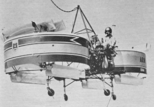
A 1960 experimental device for the development of a flying platform. Designed by Dr. Heidelberg. Lift and propulsion were supplied by several propellers. The props were driven by compressed air supplied by a compressor on the ground.
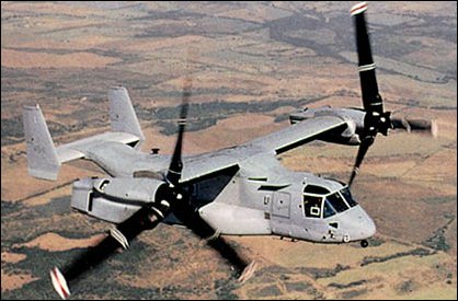
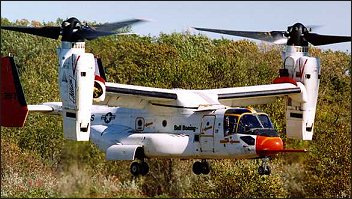
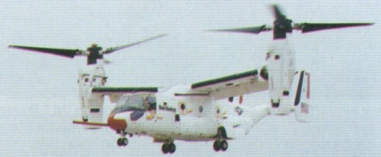
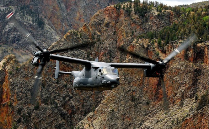
The Bell company brought a history of vertical-lift Tilt-Engine system development to this program when it combined with Boeing in the early 1980s. The company had demonstrated such a system with the XV-3, proving that it was possible to turn wingtip rotors from a vertical position to horizontal, thus providing the thrust to lift the vehicle off the ground and then transition to horizontal flight. The XV-3 was followed by the XV-15, which would closely resemble the V-22, with the XV-15 initially serving as the test vehicle for the V-22. During the early 1980s, the Bell-Boeing competed for the Joint Services Advanced Vertical Lift Aircraft (JVX). Then, on April 26, 1983, the joint team was awarded the contract to begin the preliminary design stage. Initially called the Bell/Boeing-Vertol JVX, the plane would later be given the V-22 Osprey designation, and later, special mission variations carrying the designations of MV-22, HV-22, and CV-22. The 1983 plan called for 1086 of the tri-service VTOLs to be produced with a total procurement cost of $25 billion, with the funding to be shared by the three services. The Navy was to assume the bulk of the obligation with 50 percent contribution. The initial requirement called for the craft to be capable of carrying 24 troops. Power for the Osprey comes from a pair of General Electric T64-GE-717 turboshaft engines, each rated at 6150hp, and the V-22 weighs about 24800kg at maximum take-off weight in a STOL configuration, and about 19840kg in a pure VTOL mode. Its empty weight is just over 14880kg. The rotor diameter is 11.6m, with an overall fuselage length of about 17.4m. With the rotors in the take-off position, the height of the vehicle is just over 6m. The width of the vehicle, with the rotors turning, is almost 26m. Those rotors are capable of rotating through 97 degrees and are constructed of graphite/glassfibre. 33 percent of the weight of the Osprey is fabricated of graphite/glassfibre. The rotors also possess separate cyclic control swashplates for sideways flight and fore-and-aft control during hover. Lateral attitude is maintained by differential rotor thrust. Once the V-22 achieves horizontal flight, the engines have assumed a position parallel to the fuselage.
The V-22 can fly backwards by tilting the rotors back past the 90-degree vertical position. Initial performance requirements for the Osprey were a cruising speed of 480km/h with a range with a full payload of over 1450km. Even though the V-22 carries a cargo designation, it does carry a nose-mounted 12.7mm multi-barrel machine gun. There are redundant systems, along with armor, in critical areas. The composite materials also provide protection, and one engine can power both rotors if required with a cross-coupling capability.
The full-scale development program began in May 1986 with the order for six prototypes. Numbers 1, 3, and 6 were constructed by Bell at Arlington, Texas, and numbers 2, 4, and 5 by Boeing at Wilmington, Delaware.
The first V-22 first flew on 19 March 1989.
The V-22 completed its first transition from propeller to wingborne flight on 14 September 1989.
The world’s first operational tilt-rotor transport, the Bell/Boeing’s V 22 Osprey tilt rotor made a successful first flight on 19 March 1989 with “near perfect performance” reported during a series of vertical take offs and landings at Arlington, Texas. The full-scale development program began in May 1986 with the order for six prototypes. Numbers 1, 3, and 6 were constructed by Bell at Arlington, Texas, and numbers 2, 4, and 5 by Boeing at Wilmington, Delaware. The world’s first operational tilt-rotor transport, the Bell/Boeing’s V 22 Osprey tilt rotor made a successful first flight on 19 March 1989 with “near perfect performance” reported during a series of vertical take offs and landings at Arlington, Texas. Wearing grey/green US Marine Corps camouflage, the fourth Bell Boeing V-22 Osprey flew for the first time from Boeing Helicopters flight test centre on 21 December 1989. The flight marked the beginning of V-22 flight test activities at Boeing’s facility in the Delaware Valley. The first flights for the last test vehicle occured in 1991. In 1995, the production of test vehicles resumed with numbers 7 through 10 for vibration, propulsion, USMC, and mating evaluations. Final assembly of the first production V-22 was completed in late 1998. In early 1998, the V-22 accomplished its first night test flight. During the test, the V-22 flew with a neutral density filter which covered the cockpit displays. This allowed the pilots, which were using night vision goggles, to operate the displays in the day mode. Also included in the flight test program was to investigate its capabilities for carry external loads. In one test, the number eight prototype carried a five-ton sling load through the transition phase with a top speed of 425km/h. The test pilot indicated that even though he could feel the load oscillating beneath him, it didn’t affect the craft’s performance. The testing showed that certain loads caused dramatic shifts in the center of gravity of the V-22, which in turn required a change in the attitude of the aircraft. It was determined that that requirement could be accomplished by changing the angle of the engine nacelles. Other tests planned at the time included a sling weight of 6765kg and a Humvee jeep. Early crashes of two prototypes, both in 2000 and resulting in fatalities, nearly did the system in. With pressure mounting to produce, and the general kinks reportedly ironed out, the system was passed for full scale service in 2006. In 1997 low-rate initial production was undertaken for 23 V-22s (called MV-22s) for the USMC. The first MV 22B Osprey tilt-rotor was delivered to the Marines in May 1999. The US Navy has ordered the HV-22 version for SAR duties and fleet logistic support, but cancelled its interest in the Osprey program (HV-22 Combat SAR) in 2001. The projected cost of these first operational V-22s had a unit cost of $32.2 million each, a figure that was down considerably than the $41.8 million projected during the full-scale development program. The plane has attracted international interest, with both Israel and Australia both showing interest in the unique VTOL. Bell is building the wing section, empennage, and powerplant nacelles, while Boeing has the responsibility for the fuselage and landing gear. Bell is also responsible for the final assembly and initial flight tests.
Boeing, in a joint project with the Defense Advanced Research Projects Agency, had begun testing its revolutionary new canard rotor/wing aircraft, known as the X 50A Dragonfly, making the aircraft’s first hover flight by 2004. It is designed to combine the speed and range of a fixed wing aircraft with the flexibility of a helicopter. Its rotor is designed to be used for take off and landing, while in flight it stops and is used as a fixed wing. The aircraft is 17.7 feet long and 6.5 feet high and weighs 1460 pounds. The rotor/wing diameter is 12 feet. It also has a fixed canard measuring 8.9 feet in span and an 8.1 foot span horizontal tail and is propelled by a conventional turbofan engine.
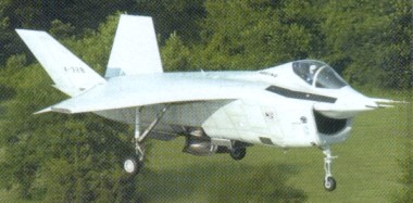
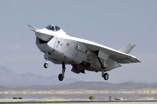
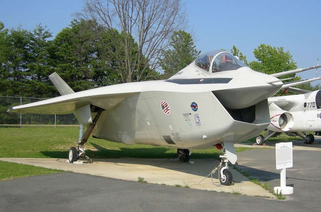
The X-32 STOVL (Short Take-Off and Vertical Landing) technology demonstrator was the Boeing Company’s response to the Department of Defense’s “Joint Strike Fighter Program” beginning in 1994. Boeing’s Joint Strike Fighter (JSF) demonstrator, the X-32A carries its weapons internally in side bays.
The X-32B achieving the first vertical landings following transition from conventional to STOVL flight. The X-32 competed – and failed – against the Lockheed submission, which went on to become the F-35.
Boeing X 32 Joint Strike Fighter Engine: General Electric YF 120 FX, 176580 N Length: 46.916 ft / 14.3 m Height: 13.123 ft / 4.0 m Wingspan: 36.089 ft / 11.0 m Wing area: 538.2 sq.ft / 50.0 sq.m Weight empty: 19999.4 lb / 9070.0 kg Crew: 1 Armament: 1x MG 27mm Mauser, max. 7700kg
Boeing X-32A Engine(s): 2 x Pratt & Whitney F135 turbofan, up to 35,000lbs thrust. Length: 50.75ft (15.47m) Width: 35.99ft (10.97m) Height: 17.32ft (5.28m) Maximum Take-Off Weight:37,920lbs (17,200kg) Maximum Range: 979miles (1,575km) Service Ceiling: 50,000ft (15,240m; 9.5miles) Armament: 1 x 20mm M61A-2 cannon OR 1 x 27mm Mauser BK-27 cannon Maximum external load: 15,000lbs approx. Seats: 1